Journal of Surface Engineered Materials and Advanced Technology
Vol.3 No.3(2013), Article ID:34220,6 pages DOI:10.4236/jsemat.2013.33025
On Some Applications of Nanoparticles Synthesized in the Gas Phase by Magnetron Discharges
![]()
Namur Research Institute for Life Sciences (NARILIS), Research Centre for the Physics of Matter and Radiation (PMR-LARN), University of Namur (FUNDP), Namur, Belgium.
Email: virginie.bouchat@fundp.ac.be, nicolas.moreau@fundp.ac.be, jean-francois.colomer@fundp.ac.be, *stephane.lucas@fundp.ac.be
Copyright © 2013 Virginie Bouchat et al. This is an open access article distributed under the Creative Commons Attribution License, which permits unrestricted use, distribution, and reproduction in any medium, provided the original work is properly cited.
Received January 30th, 2013; revised March 1st, 2013; accepted May 4th, 2013
Keywords: Nanoparticles; PVD; Plasma; Nanocluster; Vapour Phase
ABSTRACT
For the seventies, scientists focused their researches to find techniques to produce high quality films. One of the ideas, for example, was to generate an ionized cluster beam (ICB) formed by inert gas condensation (IGC) from evaporation of material. This method generates non-agglomerated nanoparticles to be deposited onto any substrate. However, the synthesis of spherical and well-dispersed nanoparticles remains, today, a major technological issue. Several trials have been performed with magnetron sputtering that has the advantage of producing very pure atomic vapour from a wide variety of solid materials or composites, and therefore in this configuration offers the possibility to synthesize nanoparticles in a gaz phase with potential numerous applications. In this paper, we describe several results of our laboratory and we show how it is possible to synthesize non-agglomerated nanoparticles with a narrow size distribution in the nm range. Detailed examples of Ag, TiO2, Au, Y, C, Co and Fe are given. We illustrate their current use in applications including catalyst to produce aligned Multi-Wall Carbon Nanotubes, seeding layer to promote anatase TiO2 crystallisation for photocatalytic material, superhydrophobic material and nanoparticle for nanomedecine.
1. Introduction
Because of their interesting optical, electronics, magnetic, mechanical and structural properties, production of welldispersed metallic and non-metallic nanoparticles with controlled size and shape is increasingly necessary to improve technological and medical applications [1-3]. Among all methodologies used today to synthesize nanoparticles, one can choose vacuum technology to produce spherical non-agglomerated nanoparticles through a vapour phase approach by DC magnetron sputtering at high pressure. The idea was introduced for the first time by Takagi et al. in 1972 to produce high quality films by ionized cluster beam (ICB) deposition [4]. The latter was generated by inert gas condensation after evaporation of film materials. A few years later, Haberland et al. propose to remove evaporation by magnetron sputtering which has the advantage of producing high-purity atomic vapour from a wide variety of solid materials or composites [5]. However, this technique requires a good understanding of the nucleation and growth processes which happen inside the plasma. That will allow a better control of dispersions and sizes of these nanoparticles onto any desired substrate.
The technique was tested for different metallic and non-metallic nanoparticles such as Ag, TiO2, Au, Y, C, Fe and Co. In this paper, results and an explanation about nucleation and growth processes are given for each experiment. The utility of synthesizing such nanoparticles for industrial and medical applications is also exposed.
2. Experimental Setup
The different NPs detailed in this paper have been all produced in a PVD system from AJA International. Inside a high vacuum chamber, a pure target (1 or 2 in diameter) used for the NPs synthesis are loaded on a DC magnetron cathode. Different power can be applied on this cathode depending on the experiment. Fluxes of inert and reactive gases are injected inside the vacuum chamber, close to the cathode surface and maintained by mass flow controllers. The chamber is pumped by a turbomolecular pump and the base pressure is lower than 10−4 Pa. During a process, pressure is kept constant according to a VAT adaptive valve. Fluxes of gases, pressures inside the vacuum chamber, powers applied on the cathode and deposition times are computer controlled. Deposition parameters for the different NPs produced in this PVD system are listed in Table 1. The clusters produced in the plasma can be collected on a substrate holder in the vacuum chamber. Distance between the cathode and the substrate may vary from 2 to 15 cm. Moreover, a heating system is capable to maintain the substrate at a constant temperature during the deposition process. The power mentioned in Table 1 is the average power over the whole 2” cathode surface.
The samples prepared on Cu grids coated with carbon or formvar films were characterized by Transmission Electron Microscopy (TEM) using a Philips TECNAI-10 microscope for the low resolution images and a Jeol 200 CX and 4000 EX for high resolution images (HRTEM). The samples prepared on Si Wafer or SiO2 film were analyzed using FEG Scanning Electron Microscopy (FEG-SEM) on a JEOL JSM-7401F microscope. Finally, the samples prepared on glasses were analysed by Atomic Force Microscopy (AFM) measurements with a Nanoscope III from Veeco Instruments.
3. Theoretical Considerations
All the NPs presented in this paper are synthesized in gas phase. Several theoretical approaches were investigated to understand the formation of such NPs in gas phase. It is generally accepted that atoms rapidly nucleate at high supersaturation of the vapour, forming a large number of very small clusters. This nucleation step can be described by addition and evaporation of monomers to the growing cluster. In classical nucleation theory, the cluster is considered as a liquid droplet and a thermally stable equilibrium is assumed. Despite of both approximations, the theory clearly confirms the strong dependence of the nucleation rate on the supersaturation and the cluster surface tension. When the amount of vapour is lower, the rate of small cluster formation is reduced. However, these small clusters continue to grow due to Brownian coagulation. The small clusters collide together to form larger spherical nanoparticles. The coagulation is favored when particles are small and the gases relatively hot. Inversely, the coalescence slows down when the mobility of the atoms in the small clusters decreases and when excess surface free energy driving forces decrease. Eventually nanoparticles may stick together to produce agglomerates of NPs.
Inside a PVD chamber, the NPs growth can be explained by a similar way. When a high pressure is maintained around the cathode, the sputtered atoms coming from the target can nucleate to form very small clusters. The nucleation rate will depend on the pressure near the cathode and the target material properties. Far from the cathode, the pressure decreases and the small clusters coalesce to form larger NPs. When the distance between the cathode and the substrate holder is important, the NPs agglomerate before landing on the substrate. Inversely, no agglomeration between the NPs is visible when the distance cathode-substrate is reduced and the NPs are deposited directly on the substrate. Moreover, the kinetic energy of the NPs formed during their ascent to the substrate is reduced by successive collisions with the carrier gas. This decrease has the advantage to ensure a soft landing of the NPs onto the substrate. By this way, the structural and the morphological properties of the NPs are retained. Their sizes will depend on the power applied on the cathode, the distance between the target and the substrate, the flow of gases injected and the pressure inside the vacuum chamber.
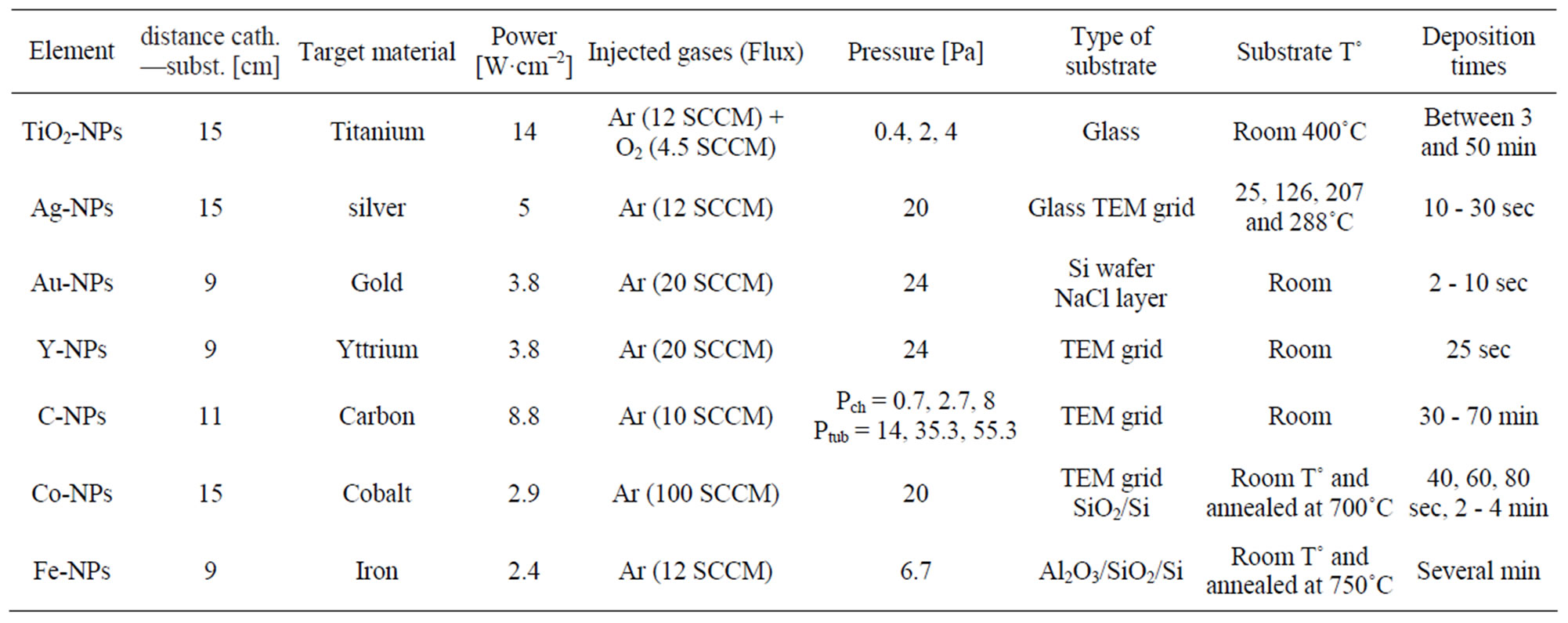
Table 1. Experimental data for the different experiments made in our laboratory.
4. Results and Discussion
In this paragraph, different experiments performed in our laboratory to synthesize non-agglomerated NPs are exposed. Table 1 summarizes the experimental conditions used to produce the samples.
4.1. TiO2-NPs
A first example of non-agglomerated nanoparticles is the deposition of titanium dioxide nanoparticles (TiO2-NPs) on glass substrates [6]. Indeed, TiO2 material is intensively studied for their photocatalytic and hydrophilic properties. This material is promising for the development of powerful anti-bacterial and self-cleaning coatings, or for building efficient solar cells. Gas used for the sputtering is argon gas mixed with oxygen reactive gas. A precise determination of the oxygen flow is required in order to get titanium oxide with the appropriate stoichiometry. Samples were made at three different pressures (0.4, 2 and 4 Pa), two temperatures (room and 400˚C) and two deposition times, corresponding to equivalent film thicknesses of 1.5 and 5 nm. First isolated TiO2-NPs appear when the pressure reaches 2 Pa after a long deposition time and at 400˚C. The mean diameter of these NPs is about 7 nm. Inversely, at 4 Pa, nanometre-size particles already appear at room temperature with a short time deposition. With a mean diameter of 11 nm, the particle sizes are clearly larger when the pressure is higher. This can be easily explained by the fact that, at higher pressure, the nucleation rate increases leading to an increase of the number of collisions between the small clusters before reaching the substrate and then an increase of the mean diameter of the TiO2-NPs. Moreover, the density of TiO2-NPs increases with higher time depositions. For long time deposition, the surface of the substrate is completely covered by a layer of NPs, irrespective of the temperature variations. All these observations strongly suggest that NPs synthesis occurs in the gas phase.
4.2. Ag-NPs
The previous experiments on TiO2-NPs have shown that the NPs are amorphous at room temperature while their structure is a mix between anatase and rutile when the temperature is raised. This is well known about TiO2 thin films and literature contains numerous researches on ways to promote anatase cristallisation at low deposition temperature. Indeed, photoinduced superhydrophilicity and photocatalytic activity are related to the crystallisation of TiO2 thin film in anatase structure. We have recently showed that silver nanoparticles (Ag-NPs) deposited prior TiO2 thin film deposition can act as seed layer to promote promote TiO2 anatase crystallisation [7]. Silver depositions were made on a TEM grid at various temperatures and deposition times. Experiment has shown that the particle size of 3 - 4 nm remains similar for each temperature. So, their size is not related to the sample temperature. Moreover HRTEM images have shown that the NPs are generally spherical and monocrystalline. If the deposition time increases, the particle density increases. However, diffusion within the substrate occurs when the deposition temperature is high revealed that the interaction between the substrate and the silver NPs was expected.
4.3. Au-NPs
Because of their interesting optical and electronic properties, gold nanoparticles (Au-NPs) have many applications in chemistry and medicine. For this third analyse, gold NPs were deposited on Si wafers. Samples are covered by Au-NPs with a mean diameter of 6.2 nm [8]. More recently, the relationship of the Au-NPs mean diameter with different deposition times of the gold layer has also been analyzed (Figure 1) and results have shown that the mean diameter of 3 nm remains more or less constant when the deposition time increases from 2 sec to 8 sec. Inversely, the density of Au-NPs clearly increases with higher deposition times. HRTEM images have also showed that all these Au-NPs are polycrystalline [8].
4.4. Y-NPs
Some experiments to synthesize Yttrium nanoparticles(Y-NPs) were performed in our laboratory for a life science project. Indeed the pure beta-emitter 90Y can be used in radioimmunotherapy for targeting tumor [9]. Therefore the synthesis of 90Y-NPs should have the advantage to increase the doses deposited inside the tumor for improving cancer treatment. Except for the deposition
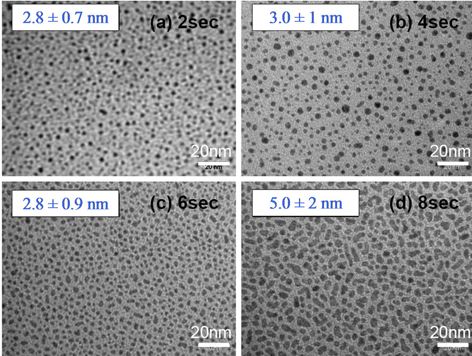
Figure 1. TEM images of Au-NPs deposited on carbon grids after different deposition times: 2 sec (a); 4 sec (b); 6 sec (c) and 8 sec (d).
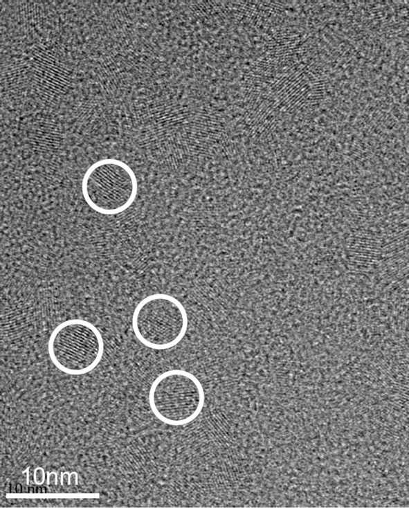
time, all experimental conditions are similar to those used to synthesize Au-NPs. Figure 2 presents a homogeneous coverage with polycrystalline material consisting of O and Y (EDX). The crystal size of the particles is 2 - 6 nm. Despite of a larger deposition time than synthesis of Au-NPs, the density and the sizes of Y-NPs are smaller, meaning that the nucleation rate is lower for YNPs. This result shows well the importance of the sputtered material properties and their surface tension values.
4.5. C-NPs
Due to their unusual chemical or physical properties, carbon nanoparticles (C-NPs) can be also very useful for industrial and biomedical applications. For this experiment, an aggregation tube was added around the cathode to maintain a very high pressure around the cathode and a very low pressure near the substrate [10]. This experimental setup allows to favour the generation of C-NPs near the cathode and to ensure a soft landing of the CNPs onto the substrates. First results have shown compact and fractal agglomerations of C-NPs, indicating that the distance between the cathode and the substrate is of prime importance. However, nucleation and particle growth in gas phase inside a plasma are more complicated than those described by the nucleation classical theory. Indeed, atoms or cluster collide with one another but also become charged by collecting plasma ions and electrons. The C-NPs can then acquire an important negative charge, often explained by a higher mobility and temperature of the free electrons than the mobility and temperature of positive ions. Non-agglomerated C-NPs are then obtained by applying a positive bias voltage on the substrate holder that is capable to extract the negatively charged C-NPs from the coalescence phase. The density increases or decreases according to the deposition time, but the mean diameter remains unchanged, even if the positive bias voltage applied on the substrate holder varies. Experiment was tested for different pressure inside the PVD chamber (0.7, 2.7 and 8 Pa) and the aggregation tube (14, 35.3 and 55.3 Pa) and the increase of the NPs mean diameter (12 ± 2 nm, 16 ± 3 nm and 20 ± 4 nm) is visible.
4.6. Co-NPs
Cobalt nanoparticles (Co-NPs) were produced in our laboratory to be used, for example, as catalyst template for the synthesis of carbon nanotubes. Cobalt was deposited on two different types of substrate (amorphous carbon and SiO2) and for different deposition times, corresponding to equivalent film thicknesses of 2, 3, 4, 6 and 12 nm. Analyses on the mean diameter have shown that the Co-NPs are agglomerated and that an increase of the Co deposition time leads to larger nanoparticles on both studied substrates [11]. Inversely to previous experiments, results indicate that the size distribution of the particles depends on the thickness of the metal layer. A first explanation should be that these Co-NPs are not synthesized in vapour phase, meaning that, even at high pressure, the nucleation phase is inexistent. The reason can be explained by a cluster surface tension very different for Co compared to TiO2, Ag, Au or Y. In this case, the presence of these nano-sized islands can be explained by the Stranski-Krastanow or Volmer-Weber growth mode as well detailed in reference [11]. A second possible explanation would be that very small Co-NPs are formed in vapour phase but these clusters may diffuse on substrate due to low interactions between them. Such diffusion of metallic nanoparticles was already observed for Ag-NPs [7]. The Co-NPs mobility is favoured when the clusters
 (a)
(a)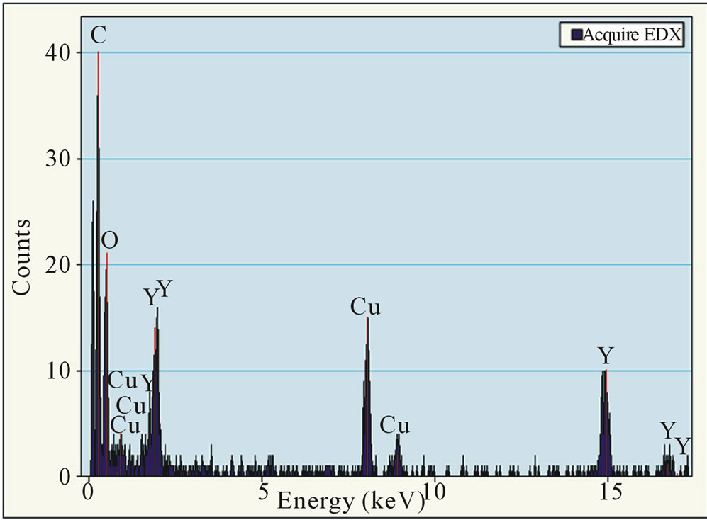 (b)
(b)
Figure 2. (a) HRTEM image of Y-NPs deposited on carbon grids after a deposition time of 25 sec and (b) elemental composition of the HRTEM image checked with Energy Dispersive Spectroscopy (EDS), mounted on the SEM microscope. Cu and C are always detected because of the support grid.
are small because the contact surface is reduced and when the substrates are amorphous (amorphous carbon or SiO2) and/or heated. Inversely, diffusion of nanoparticles stops when they meet a defect on the substrate or other nanoparticles already deposited on this substrate. In this last case, the incoming nanoparticle can interact with other deposited nanoparticles by coalescence to form a larger spherical nanoparticle or by aggregation. At larger deposition times, the number of small cobalt clusters which reach the substrate increases. All these Co-NPs diffuse and coalesce to form bigger and bigger nanoparticle size at larger deposition times.
For obtaining non-agglomerated Co-NPs, all samples were annealed at 700˚C under hydrogen for periods of time ranging from 2 to 12 min. Indeed, at high temperature, cobalt atoms can detach from the Co-NPs and diffuse on the surface of amorphous substrate. For Co-NPs deposited on amorphous carbon, the thermal annealing treatment at different times has clearly an influence on the particle size. Non-agglomerated quasi-spherical CoNPs of 13.0 ± 5.0 nm are visible only after a short deposition time and a 12-min thermal annealing treatment. For Co-NPs deposited on SiO2, there is a very low influence between the annealing time and size of the particles. Smallest Co-NPs with a mean diameter of 13.5 ± 7.8 nm are obtained with a short deposition time and a 2-min thermal annealing treatment. Finally, for the same conditions of deposition and annealing time, Co-NPs formed on the amorphous carbon substrate are always larger than those formed on SiO2 substrate. The difference of behaviour between these both substrates after annealing was explained according to Monte Carlo simu0 lations by varying the detachment and diffusion rates [11]. All these results show that the size distribution of the particles depends on the thickness of the metal layer, the type of substrate and the annealing time.
4.7. Fe-NPs
As Co-NPs, iron nanoparticles (Fe-NPs) can be used as catalyst template for the synthesis of aligned carbon nanotubes. The main challenge, in this field, is to tailor the catalysts in order to allow the formation of catalytic nanoparticles on the substrate surface in a controlled way. By this way, the morphology and type of carbon nanotubes produced are directly linked to the size and the dispersion of metallic nanoparticles onto the substrate surfaces. Generally, the chemical elements involved for carbon nanotubes growth are transition metals (such as cobalt, nickel and iron) lying onto substrate surfaces. The substrate can interact both physically and chemically with the metal catalyst particles. As previously said for Co-NPs, the substrate plays an important role in the dispersion of nanoparticles. The substrate can also interact chemically with the metal particles, dramatically affecting its catalytic activity. For example, we have shown that in the catalytic system Co deposited onto Si wafers with native silicon dioxide, the Co-NPs reacted with the substrate surface to form Co2SiO4 during the annealing treatment before nanotubes growth [11]. This problem can be overcome by the use of buffer layer between the metal catalyst and the Si substrate. The latter increases the efficiency of the carbon nanotube growth process by avoiding undesired chemical interaction between catalyst and substrate. Moreover, the dispersion and the shape of the nanoparticles can be controlled. A typical example is to use an Al2O3 buffer layer decorated with dispersed Fe metal nanoparticles (Figure 3). The buffer layer is also deposed by magnetron sputtering. Once the catalysts are prepared, the carbon nanotubes were grown by thermal catalytic chemical vapor deposition technique at 750˚C, using ethylene as carbon source, argon as carrier gas and hydrogen. Before the synthesis, the catalysts were annealed in a mixture Ar/H2 (120/130 sccm) for 30 min. at the growth temperature. This thermal annealing under hydrogen allows the formation of metallic iron nanoparticles at the buffer surface, which catalyze the nucleation and growth of carbon nanotubes. After annealing, a mixture ethylene/hydrogen (35/130 sccm) was introduced to synthesize the CNTs. As results, in the first case using the catalytic system Co/SiO2, the growth of carbon nanotubes can be observed without alignment on the surface (not shown), certainly explained by a lower efficiency of this type of catalyst due to nanoparticles/substrates interactions. Using a buffer layer and the system Fe/Al2O3/ SiO2, well-aligned carbon nanotubes were synthesizedsuccessfully (Figure 4) [12]. Of course, comparison between the two catalytic systems has been made considering the same range of particle size.
5. Conclusion
In this paper, we have shown that high-pressure DC magnetron sputtering, followed or not by annealing of the
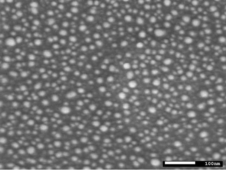
Figure 3. Scanning electron microscope image of the catalytic system constituted of Fe (6 nm)/Al2O3 (30 nm) sputtered on SiO2/Si substrates.
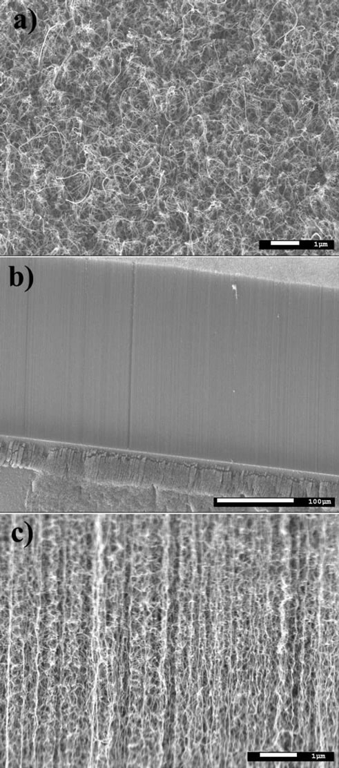
Figure 4. (a) top, (b) and (c) side scanning electron microscope views of the synthesized vertical aligned multi-wall carbon nanotubes.
substrate, can be used to generate high purity and non-agglomerated nanometric particles such as TiO2, Ag, Au, Y, C, Co or Fe. All these NPs are firstly synthesized in vapour phase by nucleation to form very small clusters. This step can be followed by coalescence of these small clusters, either in vapour phase or after diffusion on the substrate. The sizes of these nanoparticles may depend on numerous factors such as the material properties of the synthesized nanoparticles, the power applied on the cathode, the pressure inside the chamber, the type and the temperature of substrate used for the deposition, the fluxes of inert gases used for the sputtering, the charge acquired by the nanoparticles inside the plasma, and the distance cathode-substrate.
6. Acknowledgements
J.-F. Colomer is supported by the Belgian FNRS as Research Associate. This work was also supported by the Belgian Walloon Region (DGO6-TARGAN project). Special thanks to Frans Tichelaar (National Centre for HRTEM, Kavli Institude of Nanoscience, Lorentzweg 1, 2628 CJ, Delft, The Netherlands) for their HRTEM AuNPs images.
REFERENCES
- M. S. Dresselhaus, G. Chen, M. Y. Tang, R. G. Yang, H. Lee, D. Z. Wang, Z. F. Ren, J. P. Fleurial and P. Gogna, “New Directions for Low-Dimensional Thermoelectric Materials,” Advanced Materials, Vol. 19, No. 8, 2007, pp. 1043-1053. doi:10.1002/adma.200600527
- O. Salata, “Applications of Nanoparticles in Biology and Medicine,” Journal of Nanobiotechnology, Vol. 2, No. 1, 2004, p. 3. doi:10.1186/1477-3155-2-3
- G. Schmid, M. Baumle, M. Geerkens, I. Helm, C. Osemann and T. Sawitowski, “Current and Future Applications of Nanoclusters,” Chemical Society Reviews, Vol. 28, No. 3, 1999, pp. 179-185. doi:10.1039/a801153b
- T. Takagi, “Ionized Cluster Beam (Icb) Deposition and Processes,” Pure and Applied Chemistry, Vol. 60, No. 5, 1988, pp. 781-794. doi:10.1351/pac198860050781
- H. Haberland, M. Mall, M. Moseler, Y. Qian, T. Reiners and Y. Thurner, “Filling of Micron-Sized Contact Holes with Copper by Energetic Cluster-Impact,” Journal of Vacuum Science & Technology A: Vacuum Surfaces and Films, Vol. 12, No. 5, 1994, pp. 2925-2930.
- L. Dreesen, F. Cecchet and S. Lucas, “DC Magnetron Sputtering Deposition of Titanium Oxide Nanoparticles: Influence of Temperature, Pressure and Deposition Time on the Deposited Layer Morphology, the Wetting and Optical Surface Properties,” Plasma Processes and Polymers, Vol. 6, No. 1, 2009, pp. S849-S854. doi:10.1002/ppap.200932201
- H. Limage, F. D. Tichelaar, R. Closset, S. Delvaux, R. Cloots and S. Lucas, “Study of the Effect of a Silver Nanoparticle Seeding Layer on the Crystallisation Temperature, Photoinduced Hydrophylic and Catalytic Properties of TiO2 Thin Films Deposited on Glass by Magnetron Sputtering,” Surface & Coatings Technology, Vol. 205, No. 13-14, 2011, pp. 3774-3778. doi:10.1016/j.surfcoat.2011.01.022
- N. Moreau, C. Michiels, B. Masereel, O. Feron, B. Gallez, T. V. Borght and S. Lucas, “PVD Synthesis and Transfer into Water-Based Solutions of Functionalized Gold Nanoparticles,” Plasma Processes and Polymers, Vol. 6, No. 1, 2009, pp. S888-S892. doi:10.1002/ppap.200932210
- V. Bouchat, V. E. Nuttens, S. Lucas, C. Michiels, B. Masereel, O. Feron, B. Gallez and T. Vander Borght, “Radioimmunotherapy with Radioactive Nanoparticles: First Results of Dosimetry for Vascularized and Necrosed Solid Tumors,” Medical Physics, Vol. 34, No. 11, 2007, pp. 4504-4513. doi:10.1118/1.2791038
- V. Bouchat, O. Feron, B. Gallez, B. Masereel, C. Michiels, T. Vander Borght and S. Lucas, “Carbon Nanoparticles Synthesized by Sputtering and Gas Condensation inside A Nanocluster Source of Fixed Dimension,” Surface & Coatings Technology, Vol. 205, No. 2, 2011, pp. S577-S580. doi:10.1016/j.surfcoat.2011.03.055
- S. Lucas, J. F. Colomer, C. Bittencourt, P. Moskovkin and N. Moreau, “Surface Phenomena Involved in the Formation of Co Nanoparticles on Amorphous Carbon and SiO2 Deposited by Magnetron Sputtering,” Applied Physics A: Materials Science & Processing, Vol. 99, No. 1, 2010, pp. 125-138.
- J.-F. Colomer, B. Ruelle, N. Moreau, S. Lucas, R. Snyders, T. Godfroid, C. Navio and C. Bittencourt, “Vertically Aligned Carbon Nanotubes: Synthesis and Atomic Oxygen Functionnalization,” Surface & Coatings Technology, Vol. 205, No. 2, 2011, pp. S592-S596. doi:10.1016/j.surfcoat.2011.03.040
NOTES
*Corresponding author.