World Journal of Nuclear Science and Technology
Vol.1 No.2(2011), Article ID:6363,4 pages DOI:10.4236/wjnst.2011.12008
Neutronic Analysis of Generic Heavy Water Research Reactor Core Parameters to Use Standard Hydride Fuel
1Department of Engineering, Islamic Azad University, Shiraz Branch, Shiraz, Iran
2School of Mechanical Engineering, Shiraz University, Shiraz, Iran
3Department of Engineering, Islamic Azad University, Aliabad Katoul Branch, Aliabad Katoul, Golestan, Iran
E-mail: *mehdi.hashemi.t@gmail.com
Received March 25, 2011; revised April 29, 2011; accepted June 1, 2011
Keywords: WIMSD-4, CITATION, Hydride Fuel, Research Reactor, Neutronic Analysis
Abstract
This research presents neutronic calculations for heavy water research reactor core substituting hydride fuel for uranium dioxide fuel. The aim of this research is feasibility analysis of reactor utilization with its original design using a new proposed fuel and changing the coolant and moderator circuit to light water. The required group constants for the CITATION code will be calculated using WIMSD-4 code. Neutronic calculations such as multiplication factors, radial and axial power peaking factor and fuel burn-up calculations are carried out by the CITATION code.
1. Introduction
Since many years of nuclear power plant operation, uranium dioxide fuel has been used as the most common fuel in light water reactors. The history of using Uranium-hydrate-zirconium composition as a fuel is older than oxide-type fuel. The properties of Uranium-zirconium hydride fuel have been reviewed in Olander et al. work [1]. Although nuclear power plants have been used for many years, scientists are seeking methods to produce optimized and economic power in nuclear power plants. Therefore, a group of scientists from University of California, and Massachusetts Institute of Technology, with financial and scientific support from Westinghouse Company, carried out a comprehensive research on hydride fuel, and decided to establish power nuclear reactors and research reactors using this type of fuel [2-4].
It has been tried in this paper to design a generic heavy water research reactor core with Uranium-zirconium hydride fuel, and carry out the reactor core neutronic calculations for feasibility analysis of reactor utilization and changing the coolant and moderator circuits to light water.
2. Methods and Materials
The methodology in this research consists of neutronic calculations of the generic 40 MW power research reactor core considering hydride fuel and light water moderator instead of uranium dioxide fuel and heavy water [5,6].
Since diffusion equations are less accurate than transport equations in mediums such as those near the boundaries as well as mediums with strong neutron absorbents, diffusion equations could not be used, and transport equations are applied instead. For simulation of fuel assembly, WIMSD-4 code has been used. WIMSD-4 is a general lattice cell program, which uses transport theory to calculate the flux as a function of energy and position in the cell. WIMSD-4 code has been extensively used for effective cross-section computations [7]. Reactor core is simulated by CITATION code and group constants such as diffusion coefficient and macroscopic cross sections, infinite multiplication factor (kinf), effective multiplication factor (keff) and fuel burn-up are calculated. This code was designed to solve problems involving the finite-difference representation of diffusion theory treating up to three space dimensions with arbitrary group-to-group scattering. The neutron flux-eigenvalue problems are solved by direct iteration to determine the multiplication factor or the nuclide densities required for a critical system [8].
Thus, using CITATION code and incorporating parameters related to transport equation which are resulted from WIMSD-4 code, the following neutronic parameters could be obtained [9].
Neutron flux; total path length covered by all neutrons in one cubic centimeter during one second. Mathematically,  , where,
  is neutron flux (number of neutrons per cm2 per second), n is neutron density, and v is neutron velocity.
Power distribution; in order to ensure predictable temperatures and uniform depletion of the fuel installed in a reactor, numerous measures are taken to provide an even distribution of flux throughout the power producing section of the reactor. Varying the fuel enrichment (fuel concentrations) in the core radially, axially, or both, variation in the poison loading (poison zoning), and suppressing the flux fluctuations in the vicinity of the control rods are the main approaches to reach uniform power distribution.
Power peaking factor (PPF); axially power peaking factor (however radial ones is present) has been calculated by dividing maximum power in each plane to axially averaged power in hot fuel assembly. Minimization of the power peaking can be obtained by making the core’s power distribution as flat as possible (to increase margins to thermal limits, e.g., critical heat flux and fuel temperatures).
Infinite multiplication factor and effective multiplication factor; a measure of the increase or decrease in neutron flux in an infinite reactor, which has no neutron leakage, is the infinite multiplication factor, kinf ( ). In other words, infinite multiplication factor is the ratio of the neutrons produced by fission in one generation to the number of neutrons lost through absorption in the preceding generation. The multiplication factor that takes leakage into account (in a finite reactor) is the effective multiplication factor (keff), which is defined as the ratio of the neutrons produced by fission in one generation to the number of neutrons lost through absorption and leakage in the preceding generation.
A fuel assembly containing 18 fuel rods, similar to the present reactor fuel assembly, is simulated. Figure 1 demonstrates a fuel assembly similar to a generic heavy water research reactor with hydride fuel [5].
In order to decrease central temperature in hydride fuel rods, helium has been replaced by the liquid metal (Pb-Bi-Sn) in the gaps. For more information on hydride fuel properties, see [1,2].
Considering the usage of hydride fuel in the calculations, it is obvious that light water plays roles of both coolant and moderator. The properties of the fuel rod used in the simulation are presented in Table 1 [4].
It is notable that boric acid is utilized as a neutron flux controller in calculations. Boric acid density ranges over 0.15 - 0.55 × 10¹⁹ (atom·cm−3).
Figure 2 demonstrates the simulated core in CITATION code.

Table 1. The properties of standard hydride fuel rod.
According to Figure 2, the simulated research reactor consists of 150 fuel assemblies, and neutronic calculations for the whole core have been performed by CITATION code.
3. Result and Discussions
Using CITATION and WIMSD-4 codes, variations of effective multiplication factor with respect to changes in atomic density of boric acid has been calculated. It is obvious from Figure 3, the multiplication factor decreases as boric acid atomic density increases. It should be noted that the effective multiplication factor will be about 1 for boric acid densities in the range of 0.15 - 0.20 × 10¹⁹ (atom·cm−3).
As a reactor is operated, atoms of fuel are constantly consumed, resulting in the slow depletion of the fuel frequently referred to as core burn-up. There are several major effects of this fuel depletion. The first, and most obvious, effect of the fuel burn-up is that the control rods must be withdrawn or chemical shim concentration reduced to compensate for the negative reactivity effect of this burn-up. Figure 4 illustrates the result of burn-up calculation.
It could be seen that while reactor operation continues, 235U and 238U density decreases (however the 238U decreases slowly in calculated period, which seems to be constant in the figure) and 239Pu density increases. The results show the slow decrease in burn-up rate in reactor life cycle which is due to flat neutron flux in operation time and better control of the reactor power.
Axial variations in power peaking factor are shown in Figures 5. In the axial direction, maximum power for each (axial) part is divided into average power of axial hot-fuel assembly. In CITATION code, reactor core is divided into 12 equal parts in the axial direction and 19 equal parts in the radial direction, and the power peaking factor is calculated in both axial and radial directions.
Focusing on the objective of minimizing power peaking, which could be considered as a constraint versus an objective, this arises because of thermal limits on the fuel. The thermal limits that are most likely to be active include the following [10]:
1) Loss of coolant accident (LOCA) peak clad temperature (PCT) limit of 1205˚C
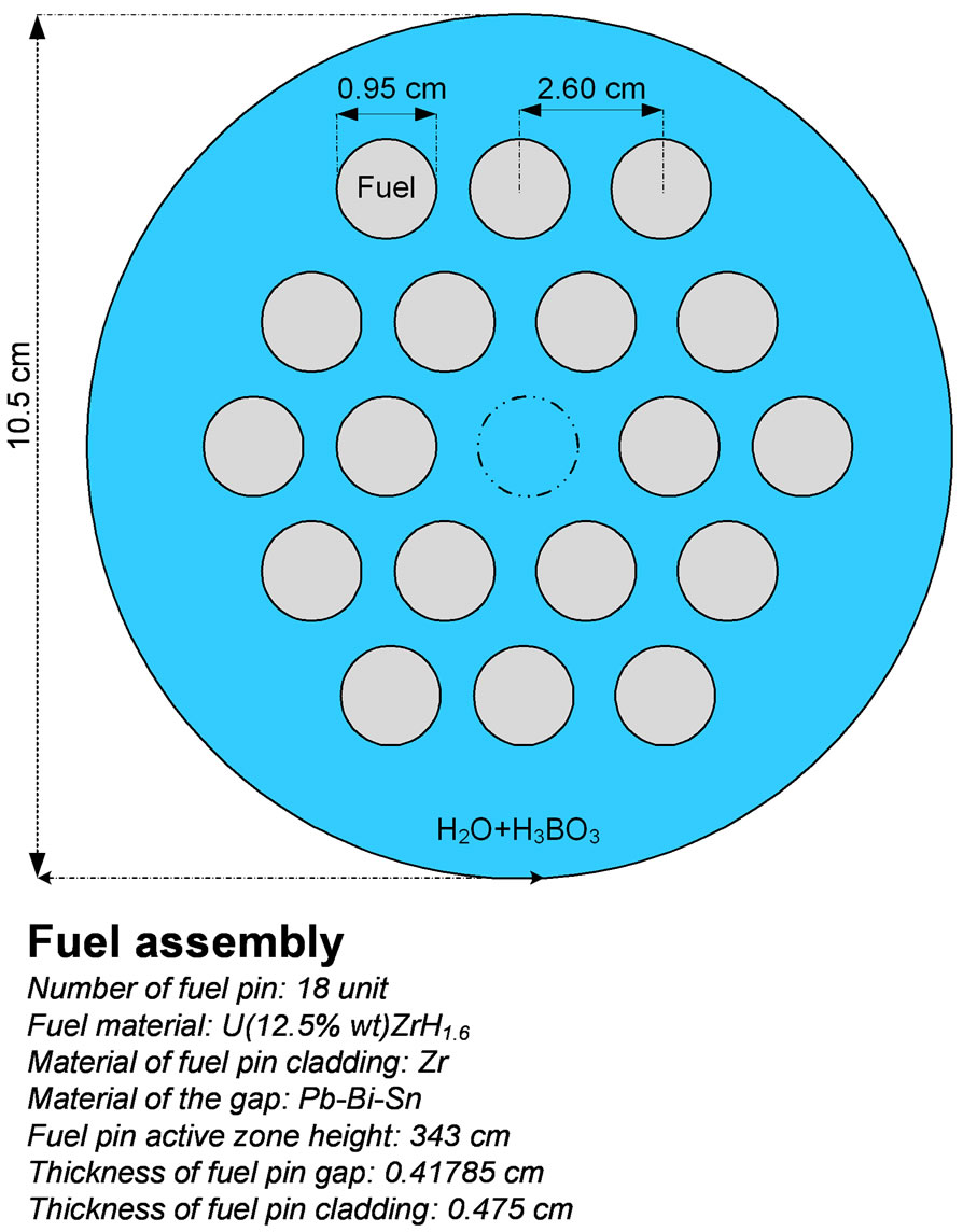
Figure 1. Cross-view of simulated fuel assembly in WIMSD-4 code.
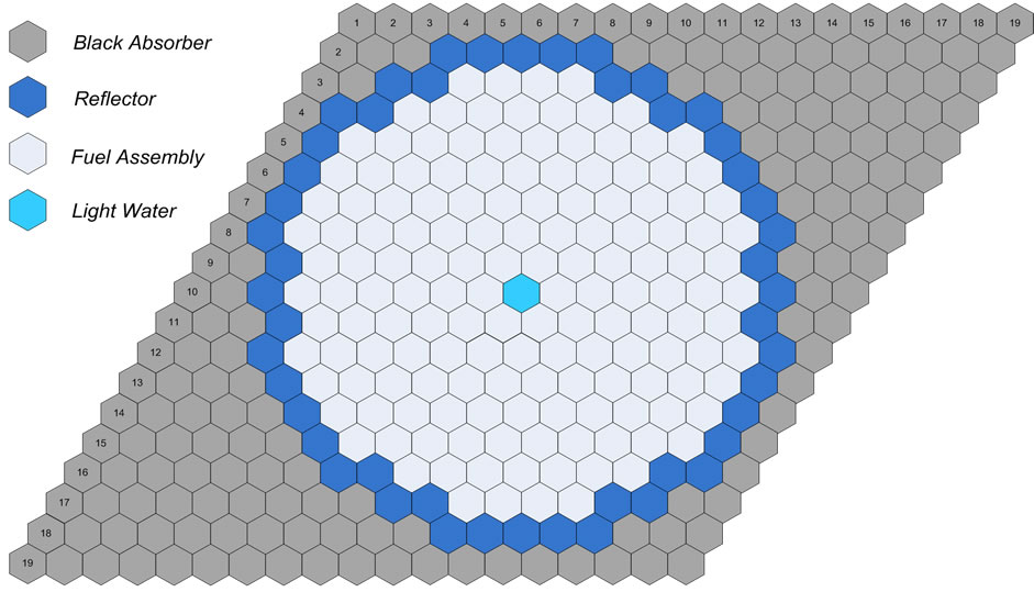
Figure 2. Cross-view of simulated reactor core in CITATION code.
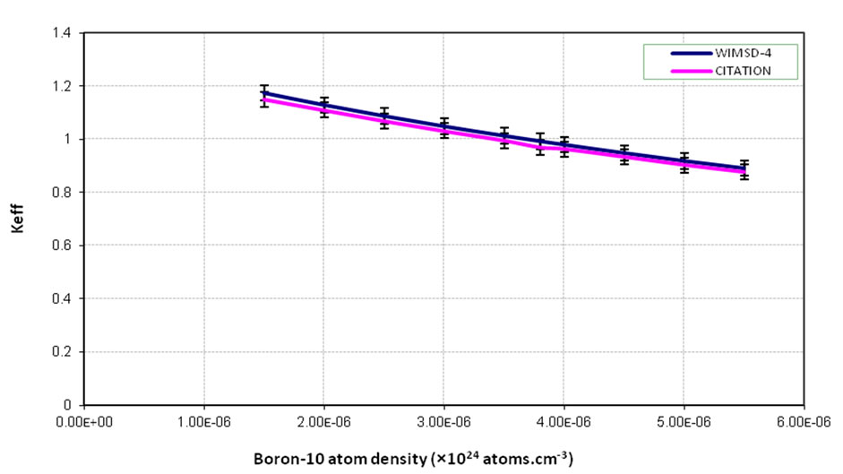
Figure 3. Changes in effective multiplication factor with boric acid density change.

Figure 4. Density changes in 235U, 238U, and 239Pu during the first working cycle (300 days).
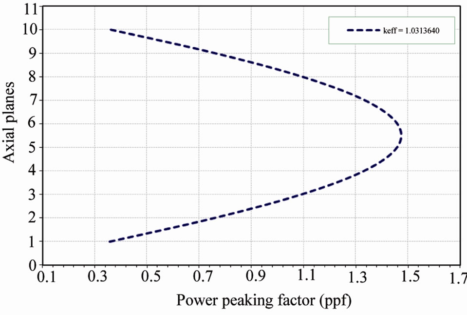
Figure 5. Power peaking factor changes in the axial state.
2) Critical heat flux (CHF), which denotes departure from nuclear boiling (DNB) for a PWR and Dryout for a BWR, not being exceeded during anticipated transients, which limits the maximum average fuel pin linear power density 3) Fuel cladding strain limit not be exceeded during anticipated transients Obviously, the calculated PPF for the generic reactor should be below the safety limits. Therefore, the reactor needs no more application of poison zoning and could be safer in heat transport terms.
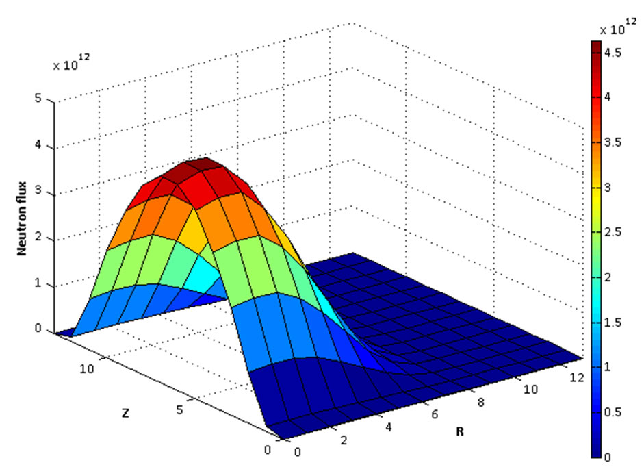
Finally, the Spatial (r, z) neutron flux distribution is calculated for the reactor core and the result is presented in Figure 6.
It is obvious from the figure that the neutron flux has no fluctuations in the core that is resulted from uniform power distribution in the core.
4. Conclusions
According to what has been stated so far, the following
 (a)
(a)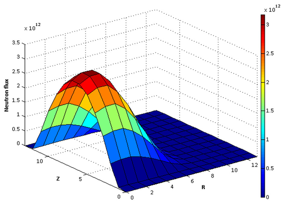 (b)
(b)
Figure 6. Spatial (r, z) neutron flux distribution of the reactor in two energy groups is given (a) 0.005 eV < E < 4 eV; (b) 9.118 keV < E < 10 MeV.
can be concluded:
Power density is higher in power plants operating hydride fuel. Using hydrogen in hydride fuel results in more neutron moderation and a flatter distribution of neutronic spectrum.
Since hydride fuel atomic density (3.7159 g·cm−3) is less than uranium dioxide fuel density (9.187 g·cm−3), a higher percentage of enrichment is required, which necessitates an economic comparison between utilization and construction expenses in the two cases. Since thermal conductivity and volumetric heat capacity in hydride fuel are greater than oxide fuel, utilizing hydride fuel in comparison with oxide fuel is safer for power plants.
Finally, it should be mentioned that fuel burn-up and power peaking factors calculations represent an economical and optimized reactor as compared to present oxide fuel reactors. Furthermore, as oxide fuel is replaced by hydride fuel in the proposed design, operation of reactor with light water moderator and coolant could be possible, which may remove world concerns regarding heavy water reactor utilization.
5. References
[1] D. Olander, E. Greenspan, H. D. Garkisch and P. Bojan, “Uranium-Zirconium Hydride Fuel Properties,” Nuclear Engineering and Design, Vol. 239, No. 8, 2009, pp. 1406-1424. doi:10.1016/j.nucengdes.2009.04.001
[2] E. Greenspana, M. Fratoni, F. Ganda, F. Ginex, D. Olander, N. Todreas, P. Diller, P. Ferroni, J. Malen, A. Romano, C. Shuffler, J. Trant, B. Petrovic and H. Garkisch, “Hydride Fuel for LWRs-Project Overview,” Nuclear Engineering and Design, Vol. 239, No. 8, 2009, pp. 1374-1405. doi:10.1016/j.nucengdes.2008.11.023
[3] A. Romano, C. A. Shuffler, H. D. Garkisch, D. R. Olander and N. E. Todreas, “Fuel Performance Analysis for PWR Cores,” Nuclear Engineering and Design, Vol. 239, No. 8, 2009, pp. 1481-1488. doi:10.1016/j.nucengdes.2008.11.022
[4] F. Ganda and E. Greenspan, “Neutronic Analysis of Hydride Fueled PWR Cores,” Nuclear Engineering and Design, Vol. 239, No. 8, 2009, pp. 1425-1441. doi:10.1016/j.nucengdes.2008.12.027
[5] F. Faghihi, E. Ramezani, F. Yousefpour and S. M. Mirvakili, “Level-1 Probability Safety Assessment of the Iranian Heavy Water Reactor Using SAPHIRE Software,” Reliability Engineering and System Safety, Vol. 93, No. 10, 2008, pp. 1377-1409. doi:10.1016/j.ress.2007.10.002
[6] M. Hashemi-Tilehnoee, A. Pazirandeh and S. Tashakor, “HAZOP-Study on Heavy Water Research Reactor Primary Cooling System,” Annals of Nuclear Energy, Vol. 37, No. 3, 2010, pp. 428-433. doi:10.1016/j.anucene.2009.12.006
[7] S. Q. B. Leite, “An Assessment of WIMS Method for Computing Collision Probabilities in One-Dimensional Annular Systems,” Progress in Nuclear Energy, Vol. 36, No. 4, 2000, pp. 367-378. doi:10.1016/S0149-1970(00)00015-9
[8] Oak Ridge National Laboratory, “CITATION-LDI2 code,” Oak Ridge, 1972.
[9] Oak Ridge Department of Energy (DOE) Fundamentals Handbook, “Nuclear Physics and Reactor Theory,” Vol. 1-2, 1993.
[10] D. G. Cacuci, “Handbook of Nuclear Engineering,” Springer Science Publications, Berlin, 2010. doi:10.1007/978-0-387-98149-9