 Journal of Power and Energy Engineering, 2014, 2, 170-175 Published Online September 2014 in SciRes. http://www.scirp.org/journal/jpee http://dx.doi.org/10.4236/jpee.2014.29024 How to cite this paper: Wang, J., Li, X.D., Si, R.Q., Cui, J.L., Fu, T. and Chen, L. (2014) Research of Integration of Setting Cal- culation System. Journal of Power and Energy Engineering, 2, 170-175. http://dx.doi.org/10.4236/jpee.2014.29024 Research of Integration of Setting Calculation System Juan Wang1, Xuedong Li2, Ruiqin Si1, Jinlan Cui1, Tao Fu1, Li Chen1 1Zhengzhou Power Supply Company of State Grid Corporation, Zhengzhou, China 2Beijing Join Bright Digital Power Technology Co., Ltd., Beijing, China Email: snowinterli@12 6.com Received June 2014 Abstract This paper expounds the main structure design and function implementation of a provincial power grid relay protection setting calculation integration system. In accordance with the actual features of the relay protection setting calculation work, setting calculation system is developed based on the project. For the development and research of integration of setting calculation sys- tem, to achieve a certain provincial power grid relay protection setting calculation and the stan- dardization of the operation and management, network and intelligent, is of great significance. Keywords Relay Protection, Integration of Setting Calculation, Engineering Setting 1. Introduction With rapid development of science and technology, information and network are used more and more widely, and the production demand for electric power system relay protection calculation and operation management automation level is higher and higher, but the overall power relay protection related analysis and calculation is difficult to meet the needs of practical production, and the gap is bigger and bigger. In recent years, the research for setting calculation and fault calculation software and development under the stimulus of demand has been rapid development. But the function implementation is a single, design structure, general is outstanding, person- alized requirements often can not meet the requirements for the current generic setting calculation system. Con- sidering that the job for a given provincial power grid relay protection calculation has a big gap to the actual situation of and existing setting system of general. For meeting the requirements of setting calculation rules, im- proving work efficiency, promoting the development of the setting calculation technology, the setting calcula- tion system [1]-[7] is developed to adapt to a provincial grid. This article detailed introduction of a provincial power grid integration setting calculation of engineering reinforcement system. 2. Integration System Design Principle 2.1. Integration System Design Principles 1) The Principle of Standardization  J. Wang et al. Meet the personalized requirements of a certain provincial power grid, and at the same time, ensure that meeting the requirements of relay protection setting calculation relevant discipline standard. 2) The Principle of Integration Build a unified data platform and unified graphical modeling. A picture and on a figure related setting calcu- lation according to their respective jurisdiction. For setting calculation in a unified data platform, which avoids the possibility of information island, implementation, and the two level of data integration. 3) Advanced Principles Adopting advanced integrated model of entire network, referencing the advanced IT technology, combined with relay protection setting newest theory achievement, which make the system has advanced technical per- formance. 4) The Principle of Safety and Reliability Relay protection of power system of the professional data must be strict, which must guarantee the safety and reliability of data. So the system in the data storage, processing, transmission, maintenance, etc. All links must be safety and high reliability. 5) The Openness Principle This system adopts the design thought of openness, adapting to dock with the different intercropping system program, data of docking, expands the application of this system. 2.2. Integration Concept Implementation 1) Building Data Integration Platform Deploy database on the database to store all date, and all the data maintenances on the server, building up a unified data platform and ensuring the consistency of the data. 2) Integration of Graphical Modeling Unified model: cut a unified substation model, unify the equipment model and unify connector model; Cut in the uniform equipment classification and identification, which can achieve consistent classification of entire network equipment and can carry on the uniform identification by the system; According to the modeling of the entire network graphics, generates a complete grid node model, to ensure that the integrated application of power grid. 3) To Build “A Net” On the basis of the unified model, the entire network model show on unified picture, the image contains all equipment information, so can reflect all network station and station equipment connection relationship between, the harmonic in the safeguard, truly “net”. 3. Systematic Design 3.1. Integration of Architecture Design In the dispatch center servers of province, there are database servers which store all data. Dispatch center clients of province and city connect database servers via electric wide area network, maintain data and meet the integra- tion requirements in the hardware architecture design. 3.2. The System Function Design 3.2.1. Graphical Modeling Drawing process is the basic link of the whole system. The achievement of all application functions is based on grid model formed by drawing mode. In drawing mode, you can establish various power components and topo- logical relation; input parameters of the elements; give principle and unit protection for each device, in order to establish province and city network. Integration network diagram of Graphical Modelingis shown in Figure 1. In the built grid model, topological relations vary with different models, precise parameters and the connec- tions among elements of all equipments. Therefore, the province and city network can simulate real power grid operations. Component model supports ‘hotspot’ function, making the model more accurate, intuitive, convenient and fast. Specifying description of the equipment and their connections, abiding by CIM model demand of IEC- 61970 standard strictly, to fit with other information system’s data sharing and data interface. Component model 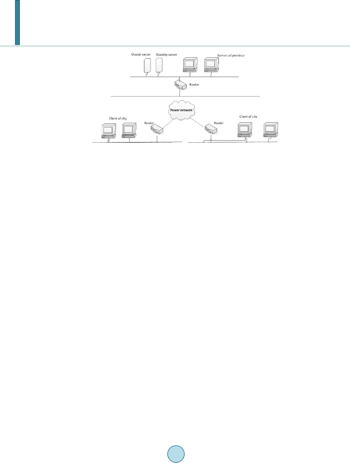 J. Wang et al. Figure 1. Integration network diagram. is divided into two levels: main network diagram and inside-station diagram. Main network diagram displays connection between stations, and inside-station diagram displays a specific connection relation between inside- station equipments. In this way, we can distinguish different levels and display grid connection structure clearly. In addition to show connections between different stations, secondary diagram is designed based on the main system of main network diagram and inside-station diagram. In secondary diagram, we can see the connection between stations, and connection relation between inside-station equipments, ensuring the grid model accurate, fast and reasonable. 3.2.2. Fault Calculation This module is the application module of the system. Based on grid model, it can simulate how to set a fault point, make the calculation, and analyze real operation according to related electrical quantities’ variation. The related functions of fault calculation are as follows: The system supports various types of short-circuit fault calculation, different choices of operation modes, plans of supplying electric on-load. The fault calculation can set the type of fault individually, choose a certain way conducting related calculation, and set different operation modes, different fault types. Also, it can calculate combination of various operation mode, complex fault, multiple faults and other more complex fault types of short-circuit fault. This module provides the calculation function of tuning parameters, equivalent impedance, extreme value of current, branch coefficient in the calculation setting conditions. It provides reliable parameters for calculation, used to calculate the setting values. The calculation of tuning parameter supports various fault setting, such as the terminal fault, one branch and adjacent branch back side bus fault, behind the outlet end fault, outlet end fault protection, and non all phase operation and so on. Considering large scale of grid and many nodes in province and city network, the system uses a network par- tition algorithm. That is to say the network is divided into several relatively small networks, solving each small network on the equivalent boundary, respectively. Based on research of regional model, segmentation branch and other regional equivalent, the mathematical model of order reduction networks is acquired, improving the speed of computation. 3.2.3. Setting Calculation Setting calculation module is an important application of this system, and operation analysis on related protec- tion is achieved in this module. Two aspects: the setting of principle and the setting of devices are put forward. As illustrated in Figure 2, the setting of principle: this system mainly considers the protection of electrical quantities in reaction side which is according to the protection of a side electric quantity to determine whether fault will occurs in the protection scope. And according to electric quantity it can be divided into stage current protection, impedance protection, zero sequence current protection etc. Protection electrical quantities of single side cannot clear the fault at the end of the line and the adjacent line outlet, so single side protection always oc- curs in some stage. However, every step protection in stage protection has to satisfy the requirements of agility,  J. Wang et al. M o d e l i n g I n f o r m a t i o n m a n a g e m e n tF a u l t c a l c u l a t i o n S e t t i n g c a l c u l a t i o n Data layer Application layerManagement layer Figure 2. The entirety functional design. speed and selectivity. The point is the key, and it is the setting of principle in front. The setting of devices: in addition to the principle of setting, other setting is according to the specific type of protection device’s device fixed value. In all these settings except the principle of valuation, there are other pa- rameters such as primary equipment parameters, a principle of protection setting and electrical quantities of sys- tem fault. It is easy to make mistakes in this part setting process which is considered individually in the system as the setting calculation most part, namely “device oriented tuning”. 3.2.4. Information Management This module is grid information management module, querying the whole grid information, electric elements, network connection and stations information. In addition, this module provides the recording system operation information, the querying the operation in all periods, in order to maintain system. The data of fault calculation and setting calculation stored in a particular form to maintain all calculation information is core management of electric power information. 4. Reinforce of Setting Function The calculation of protection setting calculation system most adopt two setting ways which manual operation and self-motion in the current market. Manual operation setting is particular but the efficiency is too low and proceed one by one; The setting range of automatic setting is larger, but it’s setting is not enough detailed and result is not perceptual intuition. In order to the setting calculation fast, detailed and intuitive, The system com- bines the advantages of manual and automatic setting, puts forward the concept of project setting and designed and refined setting calculation to draw within the scope of the equipment, then the protection setting will show on the fixed value configuration diagram intuitively. 4.1. The Practicability of Project Setting In the operation of the power grid, the equipment protection setting value is reasonable or not and the cooperate relationship between equipment whether can continue to meet the requirements in station when a new station is input or maintained and the structure of grid operating change over. Often needs to consider station put into op- eration or overhaul involved in the various equipment and Future extension series within the scope of the adja- cent devices at the same time. Then introducing the concept of engineering setting and proceed specific and de- tailed setting calculation for equipment component within the project. That ensures the power grid structure change spread to relevant equipment operation safety of fixed value and greatly reduces the workload of setting calculation through setting calculation of this project. 4.2. The Rationality of the Project Scope Headings, the establishment of the project of setting calculation, two parts is setting and checking. The selection of setting equipment give priority to with manual selection and support to pick up graphics primitive, load the project setting range according to the manual selection of equipment components. Check part automatic exten- sion level of network equipment, auto-loading related equipment of setting device, and support manually select and delete elements based on the setting range of load. Used to checking computation for run fixed value, check the setting value is reasonable or not, check cooperative relationship between run fixed value of related equip- 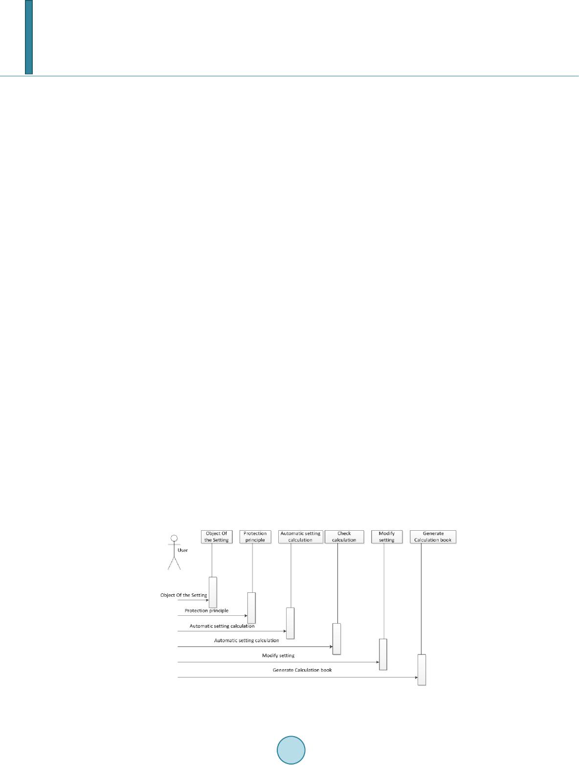 J. Wang et al. ment, provide the basis for adjustment of the fixed value setting equipment was put into operation. 4.3. The Intuition of Engineering Setting Engineering setting interface can be intuitive show relevance principle of all selected equipment components, and introduce fixed value configuration diagram which display actual connection relationship of the selected equipment, and intuitive show run fixed value of related equipment. Make cooperate with condition of put into operation conditions of the fixed value and equipments show together, and more intuitive. 4.4. Memorability of Engineering Setting The system provide save function of setting calculation of engineering, category save according setting time of engineering and equipment. People can view the saved setting calculation of engineering, to get the project set- ting calculation results of different period and provide data basis for put into operation of new fixed value by data management center. Access to relevant information of grid in the different periods of maintenance equip- ment was put into operation, provide historical information for network changes through related content of the engineering setting. 4.5. The Project Setting Function Implementation Engineering setting process is that selected setting object within the scope of the project; In view of the actual situation, selecting the principle of setting; To select good object, calculating the setting according to the princi- ples; Relevant equipment for automatic check for the selected scope, calculation of verification of setting fixed value is reasonable; Setting fixed value of unreasonable artificial manually adjust; Generate calculation, a de- tailed record setting value of the selected based on the setting process. In the process of setting, principles of selection can be accurate to a particular device of protection of a par- ticular period of protection and can also be used for multiple equipment setting principle of multiple protection more sections set randomly, and the operation is simple. The setting parameters of support are in makeup and the parameters can also be performed in makeup, which select the corresponding operation mode and calculate the required parameters during setting process. Setting calculation results can be used to display on the fixed value configuration diagram. and within the scope of the project shows the final adjusted fixed value. So engi- neering setting make full use of the manual setting and automatic setting, which is a new and practical means of setting calculation. 5. Conclusion As illustrated in Figure 3, the design and development of this system perfectly solved setting calculation and the normalized from the source of the power grid model. This system combined with the actual situation of a certain provincial power grid operation, which deepen the design and developed the calculation and application of en- Figure 3. Engineering setting operation sequence diagram.  J. Wang et al. gineering setting, effectively improved the work efficiency. Through the application of the integrated system, it helps to cultivate professional setting calculation of high technology talents, promotes the construction of the setting calculation and promotes the level of job for setting calculation and then on a new step. References [1] Qian, K.J. and Yua n, Y. (2007) Distributed Generation Technology and Its Impact on Power Systems. Relay, 35, 25-29. [2] Liang, Y.W., Hu, Z.J. and Chen, Y.P. (2003) A Survey of Distributed Generation and Its Application in Power System. Power System Technology, 27, 71-76. [3] Wang, C.S., Xi ao, Z.X. and Wa ng, S.X. (2008) Synthetical Control and Analysis of Microgrid. Automation of Electric Power Systems, 32, 98-103. [4] Wang, Z.Q., Zhu, S.Z. and Zhou, S.X. (2004) Impacts of Distributed Generation on Distribution System Voltage Pro- file. Automation of Electric Power Systems, 28, 56-60. [5] Chen, L., Zhong, J. and Ni, Y.X. (2006) Optimal Reactive Power Planning of Radial Distribution System with Distrib- uted Generation. Automation of Electric Power Systems, 30, 20-24. [6] Yi, X. and Lu, Y.P. (2006) Islanding Algorithm of Distribution Networks with Distributed Generators. Power System Technology, 30, 50-54. [7] Lu, Z.G. and Dong, Y.X. (2007) Service Restoration Strategy for the Distribution system with DGs. Automation of Electric Power Systems, 31, 89-92.
|