 Journal of Power and Energy Engineering, 2014, 2, 147-153 Published Online September 2014 in SciRes. http://www.scirp.org/journal/jpee http://dx.doi.org/10.4236/jpee.2014.29021 How to cite this paper: Xia, C.J., Xie, Y.G. and Zhou, Y. (2014) Research on the Optimized Network Configuration of DC Blocking Device. Journal of Power and Energy Engineering, 2, 147-153. http://dx.doi.org/10.4236/jpee.2014.29021 Research on the Optimized Network Configuration of DC Blocking Device Chengjun Xia, Yinggeng Xie, Yun Zhou School of Electric Power, South China University of Technology, Guangzhou, China Email: ygxie2012@163.com Received June 2014 Abstract HVDC transmission system has considerable impact on the surrounding power transformers when the system is running in the unipolar ground mode, which will cause the DC magnetic biasing phenomenon on transformers. This problem would be more serious, after commission and opera- tion of UHVDC transmission system in China. According to the Guangdong power grid under the influence of DC magnetic bias seriously, but little research about the using of blocking device, this paper proposed an optimization scheme about the usage of blocking device combination. Firstly, the subject studied the method of suppressing transformer neutral point DC depending on analy- sis the mechanism of magnetic biasing, and then found out the changes of power grid after using the capacitance blocking device which is popular used by Guangdong power grid. The particle swarm optimization (PSO) has been used to find a better way to suppress the DC in power grid, and combined with NSGA to solve the mixed integer programming problem. The final data valida- tion of this method is valuable in engineering application. Keywords Unipolar Ground Mode, DC Magnetic Biasing, Particle Swarm Optimization, NSGA, DC Blocking Device 1. Introduction In recent years, with the fast development of HVDC technology, high voltage and even ultra high voltage DC transmission technology is widely used in many areas of our country. Bipolar HVDC transmission system is more common, and it has unipolar ground return operation mode. Because of the earth is a good conductor of electricity, DC will be injected into the earth through the grounding electrode, and then such DC flows into the power grid via transformer neutral point, thus causing the DC magnetic bias and causing serious threat to the running of the power grid [1]-[5]. DC magnetic bias phenomenon is not conducive to the safe operation of power grid. On one hand, it leads to the saturation of transformer core, and the noise and vibration of trans- former increases [6]. On the other hand, the distortion of excitation current made transformer become a source of harmonic, and the result is the harmonic became the threaten of stable operate of power grid. Therefore, find- ing and effective inhibition method is very necessary. The majority of blocking device in Guangdong power grid is using capacitance, so paper mainly analyzes the 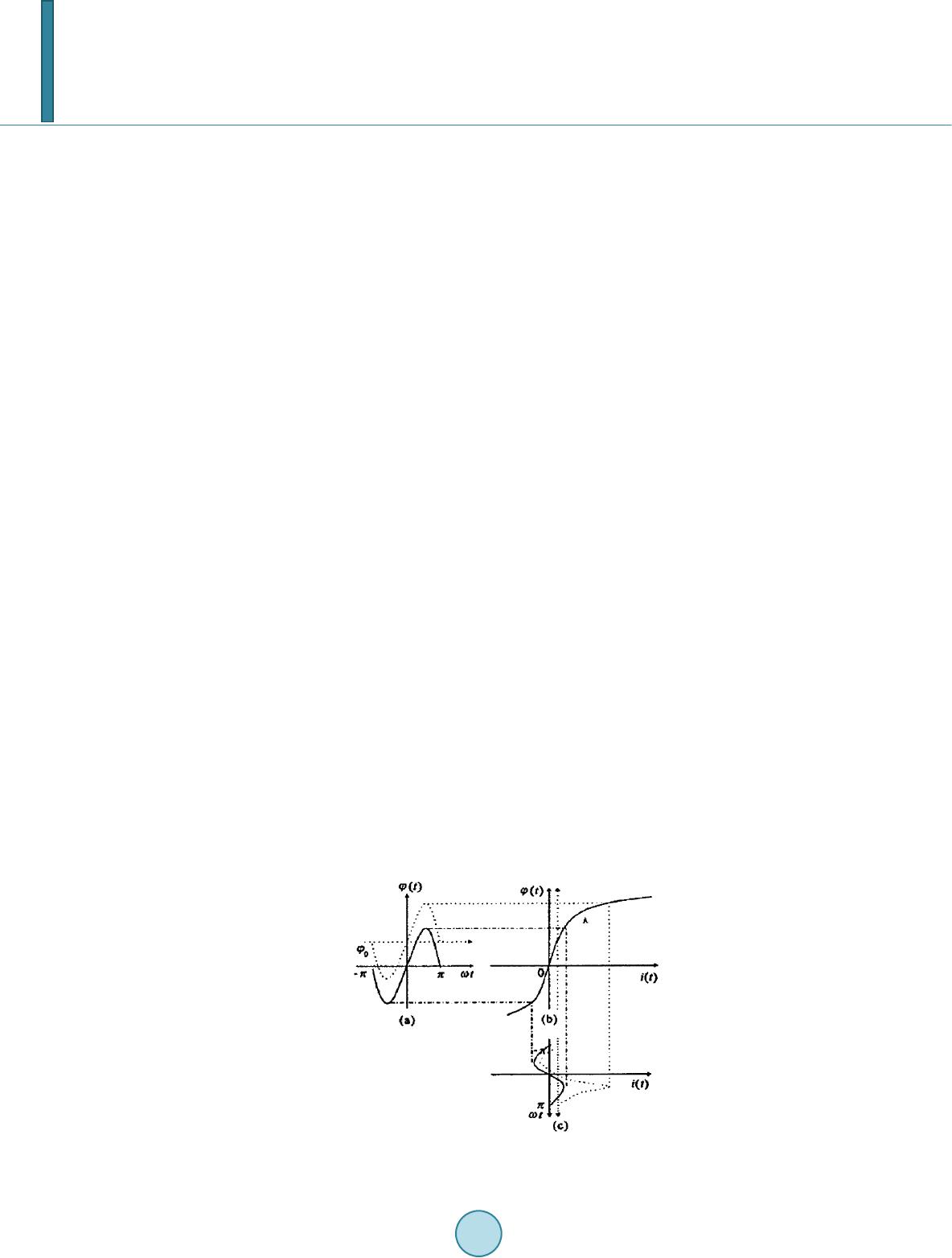 C. J. Xia et al. mechanism of capacitance blocking device, and proposes a new scheme about the combined use of blocking de- vice. This new method is base on particle swarm optimization (PSO) and NSGA, and we found that it is suitable in the field of mixed integer programming problem. 2. The DC Magnetic Bias 2.1. Distribution in Power Grid Take the common two terminal HVDC system as example, it can be divide into three types, such as unipolar system, bipolar system and back-to-back system. Bipolar system is widely used because of its flexible operation and reliable transmission. At present, all of the HVDC transmission system in Guangdong is bipolar style. When the HVDC system working in unipolar ground mode, large amount of current will flow into the ground, and a constant electric field has been built in the soil. If two stations have different potential and connected by AC line, the grounding current will flow into the power grid through the transformer neutral point easily. Different kind of transformer can work under the different level of DC magnetic bias. 2.2. The Mechanism of DC Magnetic Bias DC magnetic bias is the abnormal working condition of transformer. DC current flow in transformer winding, so that a DC magnetic potential or DC magnetic flux establish in the iron core of transformer, and then resulting many electromagnetic effect [7]. As shown in the Figure 1, the excitation characteristics curve of transformer. In Figure 1(a), the dotted line shows the magnetic flux affected by DC current, and the solid line is the curve of magnetic flux without DC. The Figure 1(b) is the magnetization curve of transformer, we can see that curve contains linear and non linear region. Figure 1(c) shows the changes of magnetization current curve when under the effect of DC current. In order to make good use of ferromagnetic material, the transformer also be designed the main magnetic flux Φ running on A point in linear region, as shown in Figure 1(b). So that it can be seen as an extra DC current flow in the magnetization winding, then the excitation current curve changes. In other word is DC and AC mag- netic flux superimposed. As a result, in half cycle of magnetic flux density increase, and the rest part of cycle decrease. So the asymmetry curve is shown as the dotted line in Figure 1(c). It is so call the distortion of excita- tion current. 3. Scheme of DC Suppression At present, people studying about DC bias suppression, no matter domestic or foreign, had proposed many methods, but the most acceptable way is resistance blocking device and capacitor blocking device [3] [7]-9]. In Guangdong power grid, capacitor suppression is the major way. The using of such device follow the rules: com- bine the data from neutral point current detection system and simulation software, and make a list about which station should be installed a blocking device. Figure 1. The excitation characteristic curve. 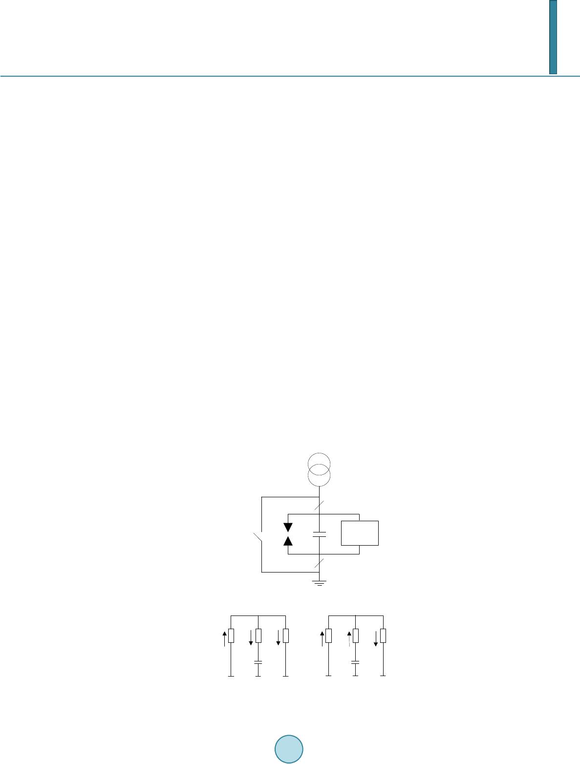 C. J. Xia et al. 3.1. Capacitor Blocking Device The capacitor is installed between the neutral point of transformer and the grounding network [8]. It is known that the inhibiting the DC is one of the characteristic of capacitor, so the capacitor device not only has a consid- erable ability to suppress the DC magnetic bias, but does not affect the circulation of AC. Schematic as shown in Figure 2. As we can see in the Figure 2, there is a by-pass switch parallel connected with the capacitor. When the grid occur an asymmetric fault somewhere, the zero sequence current will flow across the transformer neutral point, so if the by-pass switch can timely short-circuit the capacitor, the capacitor can avoid to receive high voltage and large current impact. The by-pass switch not only reduces cost, but improves the safe level of capacitor. The protective gap is used to prevent the voltage of transformer neutral point beyond the insulation level. By-pass protection device is going to prevent capacitor be broke down by ultra-voltage, which also occur when AC sys- tem fault or lighting strikes. The isolation switches near capacitor is used to make sure the maintenance without electricity. 3.2. Changes of Current Distribution In order to suppress the neutral point DC effectively, people usually access blocking device. The device is ar- ranged between the transformer and the earth. Using the blocking device is likely to change the framework of grid, so it will change the value and direction of current. For the convenience of quantitative analysis, there are three transformers working in AC network. The dia- gram of current trend is shown in the Figure 3. When the relationship between the current is I1 = I2 + I3, and the capacitor locate in the branch 2, just like the Figure 3(a). Now the current I2 = 0, and I1 = I3, so the adoption of capacitor lead to the increase of I3, in other words is the situation of NO. 3 transformer get worse. However, when the relationship is I3 = I1 + I2, and the capacitor is locate in branch 2 as well, as shown in Figure 3(b), current I2 and I3 reduce at the same time. It means, in the power grid, different blocking device scheme will have different result of current distribution. So researching the combination of blocking device is necessary. 4. Blocking Device Combination Optimization According to the study we made before, the combination of blocking device is innumerable, so there might exist a better way, which can suppress most of the DC but with the least investment. Transformer By-pass protection device Protection gap C By-pass switch Isolation switch Isolation switch Figure 2. Schematic of capacitor blocking device. Figure 3. Diagram of capacitor changes the current. 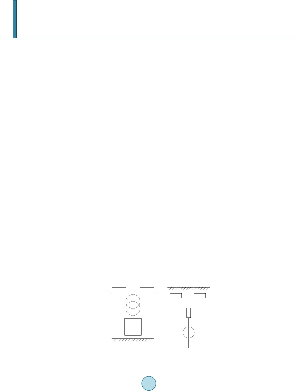 C. J. Xia et al. 4.1. Mathematical Model In the network with multiple transformers and wires, we can see each transformer as a network node and see the wire as a connection line. Then using the node voltage method (1) where Y is the admittance matrix of every node in network, U is the voltage of node, I is the current flowing into the node. Inspired by the Equation (1), the paper adopts following model to calculate the distribution of current. This model can be divided into two parts, the upper part is the model on the earth, and the lower part is the model underground, as shown in Figure 4. In the diagram, the UB is the transformer bus voltage, and the branches connected with the bus node named RL is the wire resistance. UM is the voltage level of transformer neutral point. RG is the equivalent resistor of soil. R is grounding resistance. And UP is the induction voltage generate by DC under the earth. As known from the grounded theory, the equation (2) where Rad is mutual resistance between AC system and DC system, Raa is mutual resistance between nodes in AC system, Id is the current in the DC grounding electrode; and Ia is transformer neutral point DC. Transformer neutral point current Ia can be calculated by the equation (3 ) where Gr is the transformer winding conductance. According to the Figure 4, the Equation (1) can be express in another way 11 12 21 220 MP B YYUI YYU = (4) where Y11 is the admittance matrix of neutral point nodes, Y22 is the admittance matrix of bus nodes, Y12 and Y21 is the admittance between neutral point node and bus node. IP is the current flow into the neutral point node (5) According to the equations shown above, transformer neutral point DC can be calculated. 11 111 111222 211122 21 [ ()()] Mmrad d UGY YYYYGEYYRI −− −−− =− −+ (6) (7) 4.2. Double Objective Optimization Algorithm Double objective optimization problem general described as DC blocking device RL RL U B U M Transformer RG RG + - U P U M R Figure 4. Diagram of the network model. 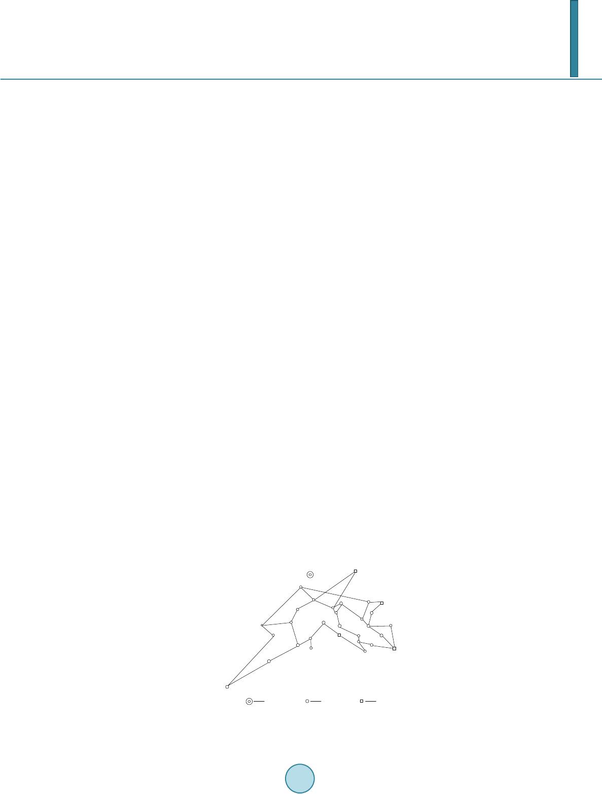 C. J. Xia et al. 12 min()( (),()) ..( )0 yFxf xfx stg x = = ≤ (8) where x named decision vector, y named target vector. The objective functions 11 21 min( ) min( ) n ai i n i i fx I fx x = = = = ∑ ∑ (9) Different from the single objective optimization problem, there is no single optimal solution of multi-objec- tive optimization, and maybe objective functions are mutually contradictory. So it usually results into a series of solutions of the objective functions, that we call them Pareto solution set. Depending on the standard particle swarm (PSO), the paper improves the algorithm with the help of the prin- ciple of NSGA, making it suitable for the mixed integer programming problem. The process of algorithm is as follows: 1) Initialize the particle swarm. Set the swarm size N, and randomly generated particle position x and particle velocity v. 2) Calculate the fitness value through objective function. 3) According to the fitness value sort the data, and then find out the non-dominated solution set. 4) Average the elements in the set, and make the result as global optimal solution gbest. 5) Calculate the individual optimal solution of each particle, and refresh the position and velocity of particle. 6) Crossover and mutation. Avoid the particles fall into the local optimal solution, and ensure the diversity of particles. 7) Judging the iteration number reach the limit value, if yes, stop the calculation, if no, return to step 2). 5. The Example Analysis Guangdong power grid now has seven HVDC transmission systems, two ultra high voltage (±800 kV) systems and five high voltage (±500 kV) systems. The ultra high voltage system named ChuSui DC and NuoZhaDu DC. But the operation time of NuoZhaDu DC is not long enough, and lack of data. So the following analysis is mainly take ChuSui DC as example. The DC magnetic bias is more serious in 500 kV stations, and too much 200 kV and 110 kV will make the calculation complicate, so this paper just consider about the 500 kV network in Guangdong. The station which is far away from the DC grounding electrode also be ignored. The DC grounding electrode of ChuSui DC, named YuLongLing, located in Guangdong, Qingyuan. The final diagram of network is shown in Figure 5. According to objective functions proposed before, using the improved PSO to calculate the optimized solution. Algorithm uses 50 random particles. The max iteration time is set to 500. The learning factor C1 = C2 = 0.9, and the inertia weight ω = 1.1. The calculation results are shown in the Table 1. Note that all the results are depend- ing on the data when the value of current in DC grounding electrode is 2500 A. DL WY DL YD JM XS SD XJ GN LD HD BJ GX ZC SX GC SJ SUI BL HL HX FY DG HZ BA PC ZJ SZ KP LA YLL The DC grounding electrode Substation Power station Figure 5. Diagram of network in Guangdong.  C. J. Xia et al. Table 1. Calculation results of DC bias current and blocking device. Substation Installation of blocking device DC with device (A) HuaDu 15.26 1 0 LuoDong 2.09 0 3.89 BeiJiao −9.07 1 0 ZengCheng 0.92 0 2.53 SuiDong −2.8 0 −0.55 ShuiXiang 1.8 0 −0.26 HengLi 24.95 0 2.8 BoLuo −28.03 0 −3.24 FuYuan 30.01 1 0 HuiZhou 55.33 1 0 DongGuan −28.95 1 0 KunPeng 30.51 1 0 ShenZhen 55.61 1 0 ZiJing 44.96 1 0 BaoAn 43.33 0 14.68 PengCheng −44.42 1 0 GuanCheng −17.69 0 −5.57 GuangNan −4.01 1 0 ShunDe 6.89 0 −0.35 XiJiang 5.91 0 3.91 YanDu −11.89 1 0 CangJiang 14.21 1 0 JiangMen −6.22 0 2.4 WuYI 10.43 0 8.9 DieLing −12.61 0 −11.4 Sum 507.9 12 60.48 a) In the blocking device column, the value 1 means that substation installs the device, and the value 0 means that substation do not use device; b) In the DC column, the positive value means current flows in the node, and the negative value means current flows out the node. From the result, when all the substations do not install the blocking device, the majority of the transformer will be affected by DC magnetic bias seriously. But after used the device configuration, the current in neutral point will sharply decrease. So the result is acceptable, and the optimization is feasible. Note that the error of calculation and the missing of data could not avoid. On one hand, the calculation of soil resistance is using the typical value. On the other hand, all the 500 kV transformers are self-coupling, that means 500 kV transformer has electric connection with the 220 kV transformer, so ignore the 220 kV transformer is imprecise. There may be an inevitable gap between the actual value and the calculation result. But being a method is under economical consideration solve the problem of DC magnetic bias, it really work at some situa- tions. The example analysis shows the effectiveness of the configuration. 6. Conclusions 1) The capacitance type blocking device has effect on the structure of network, and refreshes the DC distribu- tion. So it is possible to make better current inhibition with less cost. 2) Standard PSO algorithm is not suitable for multi objective optimization problem. But with the help of NSGA, PSO can be used in the 0-1 mixed integer programming problem.  C. J. Xia et al. Acknowledgements This work was financially supported by The National High Technology Research and Development Program (863 Program) (2011AA05A102). References [1] Kuai, D.Z., Wan, D. and Zhou, Y. (2004) Influence of DC Magnetic Bias on Transformers. Electric Power, 37, 41-43. [2] Cheng, H.F., Ruan, J.J. and Zhang, N. (2006) DC Magnetic Bias Induced Current Effects on Transformer and Re- stricting Methods. High Voltage Engineering, 32, 117-120. [3] Zhu, Y.Y., Jiang, W.P. and Zeng, Z.H. (2005) Studying on Measures of Restraining DC Current through Transformer Neutrals. Proceedings of the CSEE, 25, 1-7. [4] Ma, W.M. (2004) Biasing Current in Converter Transformer. High Voltage Engineering, 30, 48-49. [5] Zeng, R., Zhan, B. and Zhao, J. (2009) Influence and Characteristics Analysis of Effect of the HVDC Ground Return Current on AC Syst e m. High Voltage Engineering, 35, 678-682. [6] Zhong, L.H., Lu, P.J. and Qi u, Z.C. (2003) The Influence of Current of DC Earthing Electrode on Directly Grounded Transformer. High Voltage Engineering, 29, 12-13. [7] Eitzmann, M.A., Walling, R. A. and Huynh, H. (1992) Alternatives for Blocking Direct Current in AC System Neutrals at the Radisson/LG2 Complex. IEEE Transactions on Power Delivery, 7, 1328-1337. http://dx.doi.org/10.1109/61.141850 [8] Picher, P., Bolduc, L. and Dutil, A. (1997) Study of the Acceptable DC Current Limit in Core-From Power Transform- ers. IEEE Transactions on Power Delivery, 12, 257-265. http://dx.doi.org/10.1109/61.568248 [9] Bolduc, L., Granger, M. and Paré, G. (2005) Development of a DC Current-Blocking Device for Transformer Neutrals. IEEE Transactions on Power Delivery, 20, 163-168. http://dx.doi.org/10.1109/TPWRD.2004.835437
|