Journal of Power and Energy Engineering, 2014, 2, 125-131
Published Online September 2014 in SciRes. http://www.scirp.org/journal/jpee
http://dx.doi.org/10.4236/jpee.2014.29018
How to cite this paper: Tang, Y.H. (2014) Francis Turbine and Governor Improved Models Considering Step Closing Law of
Guide Vanes for Power System Stability Analysis. Journal of Power and Energy Engineering, 2, 125-131.
http://dx.doi.org/10.4236/jpee.2014.29018
Francis Turbine and Governor Improved
Models Considering Step Closing Law of
Guide Vanes for Power System Stability
Analysis
Yuheng Tang
School of Electrical Engineering, Wuhan University, Wuhan, China
Email: Yuheng_Y ang@ 126.com
Received June 2014
Abstract
The Francis turbine governing system models in PSD-BPA can’t precisely reflect the actual char-
acteristics. Endeavor was done in this paper to solve the problem. An improved model of actuating
mechanism was developed, which could reflect the step closing characteristic of hydro guide vanes.
The effect of the inflection point value of actuating mechanism on load rejection was analyzed
based on simul ati on. The non-linear Francis turbine model with power versus gate position mod-
ule was researched in this paper. Based on field test, comparisons of simulation results with
measured data were presented. The analysis demonstrates that the improved models of Francis
turbine and governor proposed in this paper are more realistic than the models of BPA, and can be
applied in power system simulation analysis better.
Keywords
Francis Turbi ne, Gov er n or, Actuating Mechanism, Step Closing Law, Improved Models,
Power System Stability Analysis
1. Introduction
As an indispensable part of hydropower generating units, hydro turbine governing system plays an important
role in sticking up for power system stability in China. The studies on power system stability are relying on
models to correctly predict system response to disturbances specified in the reliability criteria. Therefore, more
precisely modeling of hydro turbine governing system can’t afford to be neglected in the research field of coor-
dinated optimization between generator units and grid. Its important application value is self-evident.
There has been endeavor in modeling of hydro turbine and governor system, but more in-depth study is nec-
essary. Different types of turbine models were given in [1], but the Francis turbine model was not validated
based on field test. Common types of actuating mechanism models were analyzed in [2], which was of great
reference value. The PID controller model developed in [3] had been incorporated into PSD-BPA and applied.
Y. H. Tang
126
An actuating mechanism model considering dead zone and saturation modules was given in [4], which was more
accurate than the linear model, but it couldn’t reflect the two-segment closing characteristic of hydro guide
vanes in practical engineering [2], leading to inaccurate simulation results in large oscillation condition.
This paper develops an enhanced actuating mechanism model including two-segment closing device module.
Then the load rejection study demonstrates that different inflection points have significant influence on the
unit’s dynamic performance. The Francis turbine model considering nonlinear relationship between gate posi-
tion and turbine power is researched. Based on measurements taken at field test, including the actuating mecha-
nism open/close test and the power-raising test, models validation is presented.
2. Francis Turbine and Governor Models
The block diagram of Figure 1 shows the basic elements of a Francis turbine-governor system within the power
system environment.
In Figure 1, wref is frequency refrence, Pref is power refrence, yref is gate position refrence, yPID is the outprt of
PID Micro-computer based governor, y is gate position, h is the head at the turbine admission, q is turbine flow
rate; Pm is mechanical power; w is frequency; Pe is electrical power.
2.1. Micro-Computer Based Governor Model
Recently in China, the regulating method of hydro turbine micro-computer based governor is Proportional- In-
tegral-Derivative. The governor consists of PID controller and actuating mechanism. The PSD-BPA PID con-
troller model [3] is used to represent the PID controller in this paper.
In practical engineering, the actuating mechanism of the governor incorporates step closing device. In the
emergency of guide vane closing, step closing device devides the guide vane closing process into two sections,
and the closing rate of each section is different. Given this fact, an improved actuating mechanism model con-
sidering step closing characteristic was developed and shown in Figure 2.
In Figure 2, Ty is the actuating mechanism time constant. T1 is the time constant of the delay module, and T2
is time constant of the feedback module.
PID controllerActuating
mechanism Generator
and load
e
P
ω
y
ref
ω
ref
p
ref
y
Francis
turbine
Water
comnduit
hq
P
m
Hydro turbine micro-
computer based governor
y
PID
Figure 1. Block diagram of Francis turbine and governor.
sp
K
sd
Ks
si
K
s
1
s
pid
y
+
_
+
+
+
PID controller for
actuating mechanism
Gate
y
Step
Closing
Device
y
1/ T
1
s
T
ε
Speed Limit 2
CLOSE
Speed Limit 1
CLOSE
Speed Limit
OPEN
Speed Limit
OPEN
Minimum
Gate 0
Maximum Gate
Opening 1
Feedback module
Figure 2. Governor’s actuating mechanism model considering the step closing law of
hydro guide vanes.
Y. H. Tang
127
2.2. Francis Turbine Improved Model
Neglecting the head loss due to friction in the conduit, no load flow and speed deviation damping effect, the per
unit flow rate through the turbine and the per unit turbine power are given by:
q yh=
(1)
m
p qh=
(2)
This model achieves a compromise between simplicity and capturing essential behavior for large-scale studies.
But nonlinear turbine effects can’t afford to be neglected. Based on this type of model, a module should be
incorporated in to reflect the non-linear relationship between gate position and turbine power [1].
In Figure 3, H0 is the static head of water column, G(s) is the transfer function of turbine conduit.
The non-linear relationship between gate position and electrical power is given by:
32
1 234
()
m
Pfya yayay a== ⋅+⋅+⋅+
(3 )
where, a1, a2, a3, a4 are the coefficients for curve fitting.
2.3. Turbine Conduit Model
For simple water conduit no more than 800 m length, the elasticity of the steel in the conduit and the compressi-
bility of water can be ignored. Using the rigid model of water column is adequate:
In Figure 4, Tw is the water time constant in the conduit. Tw can be identified based on the particle swarm op-
timization algorithm. The fitness function is given by:
[ ]
2
0
1
1() ()
N
k
fitnessy kyk
N
=
= −
(4)
where N is sampling number, and y(k) is the output of the model used for simulating, and y0(k) is the measure-
ments recorded at field test.
3. Simulation Studies
Xiaowan hydroelectric power station is on the Lancang River in Nanjian County, Yunnan Province, southwest
China. It is the third largest hydroelectric power station in China. The models validation is combined with
measurements at Xiaowan hydroelectric power station.
The simulation and analysis of load rejection are presented in chapter A. Then the validation of actuating
mechanism model and Francis turbine model is made in chapter B and chapter C respectively. Chapter A and
chapter C use the same simulation system. The general view of the simulation system is shown in Figure 5.
The synchronous machine 5 orders practical model and a simplified voltage regulation and excitation system
model [5] were used to simulate the generator and excitation system.
÷
×
×
+
0
H
×
q
'
h
y
1 ()Gs
M
P
Gate position vs
Turbine power
h
Figure 3. Francis turbine model with mechanical power versus gate position module.
sTw
qh
Figure 4. Non-elastic water column model.
Y. H. Tang
128
GS
Generator
and excitation
Francis turbine
and governortransformer
Load of the
hydro plantLoad
I
n
f
i
n
i
t
e
b
u
s
line
u
p
s
t
r
e
a
m
Water
conduit
transformer
Figure 5. Simulation system general view.
3.1. Simulation of the Two-Segment Closing Characteristic of Actuating Mechanism
In the load rejection study, the simulation system is shown in Figure 5. The length of the water conduit of
Xiaowan hydroelectric power station is no more than 800 m. Thus the rigid model of water column was applied.
The actuating mechanism model developed in this paper and IEEE nonlinear turbine model were used to repre-
sent the turbine-governor.
Different value of inflection point was set respectively in order to study the influence of the two-segment
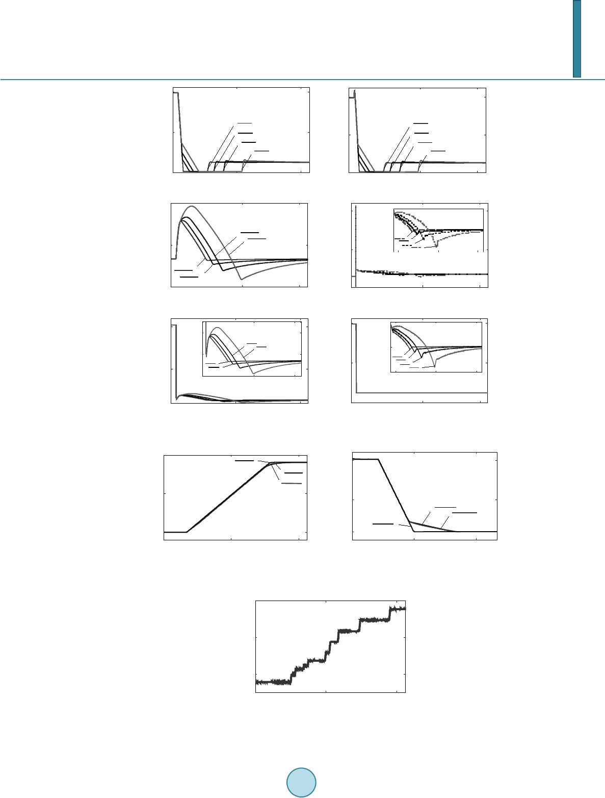
closing characteristic. The generator trips when t = 8 s. The 100% load rejection simulation results are shown in
Figure 6.
It can be seen from Figure 6:
There is an observable difference between the simulation results of four types of inflection point value. With
the increasing of inflection point setting value, the over-speed event will be more serious during the load rejec-
tion. The dynamic time lasts longer and the maximum deviation of the frequency excursion increases. The same
phenomenon resulting from serious over-speed happens in the dynamics of other electrical quantities, including
generator voltage, rotor angle, electrical power.
3.2. Validation of the Actuating Mechanism Model
The actuating mechanism model in Figure 2 and BPA model were applied to the actuating mechanism open/
close test of Xiaowan Unit #2. The recorded output of PID controller was used to drive the model response.
Figure 7 shows the comparison of simulated and recorded responses.
It can be seen from Figure 7:
1) Both of the improved model and the BPA model can correctly simulate the gate-opening process, and the
response of the improved model is more accurate.
2) The measured governor response (gate position) and the simulated response of the improved model are in
very close agreement in the process of gate-closing, while the BPA model can’t reflect the step closing charac-
teristic.
3) The actuating mechanism closes the guide vane according to speed limit of each section. And the inflection
point value of Xiaowan 2# unit is 0.13.
3.3. Validation of the Francis Turbine and Governor Models
The validation is based on power-raising test of Xiaowan 2# unit.
The rated head of the turbine is 216 m, and the rated power is 700 MW. The actual head is 171 m, and the
maximum power is about 470 MW.
#2 unit online, 210 - 350 MW power-raising test was conducted by stepping the power reference, using type
TCFZ-35A multifunctional tester for hydro turbine governing system to record the input signal of governor, step
responses of relative variables, including gate position and electrical power. The actual power reference signal is
shown in Figure 8.
In the simulation, the rigid model of water column was used, and four model combinations were applied to
represent the turbine-governor system:
Combination 1: The Francis turbine and governor improved models proposed in this paper;
Combination 2: IEEE nonlinear turbine model and the improved actuating mechanism model in Figure 2;
Combination 3: BPA ideal turbine model and the improved actuating mechanism model in Figure 2;
Y. H. Tang
129
090 180
0
0.4
0.8
t/s
y p.u.
4
3
2
1
0
180
100
t/s
0.8
0.4
0
Gate position (y p.u.)
1. Inflection point value=0
2. Inflection point value=0.13
3. Inflection point value=0.2
4. Inflection point value=0.3
0100 180
0
0.4
0.8
t/s
Pm p.u.
1
2
34
0
180
100
t/s
0.8
0.4
0
Mechanic power (P
m
p.u.)
1. Inflection point value=0
2. Inflection point value=0.13
3. Inflection point value=0.2
4. Inflection point value=0.3
0100 180
1.15
1.6
t/s
w p.u.
2
1
4
3
0
180
100
t/s
1.6
1.15
0.7
Frequency (w p.u.)
1. Inflection point value=0
2. Inflection point value=0.13
3. Inflection point value=0.2
4. Inflection point value=0.3
010 01 80
1. 01
1.025
t/s
Ua p. u.
0
180
100
t/s
1.025
1.01
0.9 95
Unit voltage (U
a
p.u.)
20 100 180
0.9995
1.001
1.0025
t /s
Ua p.u.
12
34
20
180
100
t/s
1.0025
1.0 01
0.9995
1. Inflection point value=0
2. Inflection point value=0.13
3. Inflection point value=0.2
4. Inflection point value=0.3
090 180
10
20
t/s
delta degree
0
180
100
t/s
20
10
0
Power Angle (
θ
/
°
)
0100 180
2
3
4
4.5
t/s
delta degree
3
12
4
0
180
100
t/s
4
3
2
1. Inflection point value=0
2. Inflection point value=0.13
3. Inflection point value=0.2
4. Inflection point value=0.3
0100 180
0
0.4
0.8
t/s
Pem p.u.
0
180
100
t/s
0.8
0.4
0
Electrical Power (P
em
p.u.)
20 100 180
0.0999
0.1002
0.1005
t/s
Pem p.u.
12
34
20
180
100
t/s
0.1005
0.0999
0.1002
1. Inflection point value=0
2. Inflection point value=0.13
3. Inflection point value=0.2
4. Inflection point value=0.3
Figure 6. Simulation results of load rejection.
08 16
0
0.5
1
t/s
y p.u.
1
3
2
0
16
8
t/s
1
0.5
0
Actuating Mechanism Open Test
y p.u.
1. Actual
2. BPA model
3. Improved model
015 30
0
0.4
0.9
t/s
y p.u.
1
2
3
0
30
15
t/s
0.9
0.4
0
1. Actual
2. BPA model
3. Improved model
Actuating Mechanism Close Test
y p.u.
Figure 7. Simulation results of positive and negative step disturbance.
080 160
0.6
0.7
0.8
t/s
Pref
0
160
80
t/s
0.8
0.7
0.6
Power reference (P
re f
p.u.)
Figure 8. Power reference signal.
Y. H. Tang
130
080 160
8
11
14
t/s
delta degree
1
2
3
0
160
80
t/s
14
11
8
Power Angle (
θ
/
°
)
1. Combination1
2. Combination2
3. Combination3
080 160
1
1.0001
1.0002
1.0003
t/s
Ua p.u.
3
1
2
0
160
80
t/s
1.0003
1.0002
1.0001
1
Unit voltage (U
a
p.u.)
1. Combination1
2. Combination2
3. Combination3
080 160
0.55
0.65
0.75
t/s
y p.u.
5
1
4
0
160
80
t/s
0.75
0.65
0.55
Gate position (y p.u.)
1. Combination1
4. Combination4
5. Actual
080 160
200
275
350
t/s
P MW
1
5
23
0
160
80
t/s
350
275
200
Electrical Power (P
em
MW)
1. Combination1
2. Combination2
3. Combination3
5. Actual
Figure 9. Francis turbine and governor models’ simulation results.
Combination 4: Francis turbine model in Figure 3 and BPA governor model.
Through curve fitting, the non-linear relationship between gate position and power was got, and the coeffi-
cients in (3) are: a1 = 6.2891, a2 = 12.2513, a3 = 8.8952, a4 = 1.9222. And Tw is 1.825 s, identified by the par-
ticle swarm optimization algorithm.
Figure 9 shows the comparison of simulation result.
The simulation results in Figure 9 validate the Francis turbine and governor models proposed in this paper. It
can be seen from Figure 9:
1) Both of the improved actuating mechanism model and BPA model can simulate the response correctly
when the fluctuation of gate reference signal is small.
2) Large head variations clearly can have a major impact on the total response of generating unit. Thus the
non-linear relationship between gate position and power will strongly influence the amount of power response.
That is the reason why the response of ideal turbine model in BPA or IEEE nonlinear model without this mod-
eling addition is significantly in error in simulation, while the measured power response and the simulated re-
sponse of the improved Francis turbine model are nearly identical.
4. Conclusions
1) The improved model of actuating mechanism can reflect the two-segment closing law of hydro guide vanes
and obtain the correct response in simulation for Xiaowan hydro generating unit, overcoming the disadvantage
of actuating mechanism model in PSD-BPA.
2) In load rejection studies, the setting value of inflection point will strongly influence the governing system
responses, including gate position, turbine power and frequency. With the increasing of inflection point setting
value, the over-speed event will be more serious during the load rejection.
3) The Francis turbine model considering nonlinear relationship between gate position and electrical power,
compared with the ideal hydro turbine model in PSD-BPA, captures the responses of Xiaowan hydro generating
unit more accurately. The Francis turbine and governor improved models considering two-segment closing law
of hydro guide vanes can be applied in power system simulation analysis better.
References
[1] Patterson, S. (2004) Importance of Hydro Generation Response Resulting from the New Thermal Modeling and Re-
quired Hydro Modeling Improvements. Power Engineering Society General Meeting, 2, 1779-1783.
[2] Wei, S.P. (2009) Hydraulic Turbine Regulation. Huazhong University of Science and Technology Press, Wuhan.
Y. H. Tang
131
[3] Wang, G.H., Pu, J., et al. (2010) Modeling and Parameter Testing of Governing System for Domestic-Manufactured
700 MW Hydraulic Turbine Suitable to Power System Stability Calculation. Power System Technology, 34, 101-105.
[4] Huang, Q.S. and Xu, G.W. (2012) Custom Model and Application of Hydro Turbine Regulating System. Automation
of Electric Power Systems, 36, 115-117. (in Chinese)
[5] Liang, J.Q. and Harley, R.G. Pumped Storage Hydro-Plant Models for System Transient and Long-Term Dynamic
Studies.