 Journal of Power and Energy Engineering, 2014, 2, 98-105 Published Online September 2014 in SciRes. http://www.scirp.org/journal/jpee http://dx.doi.org/10.4236/jpee.2014.29014 How to cite this paper: Huang, M.Y., Dong, L., Zhang, J., Wang, J. and Hao, Z.G. (2014) Research on the Differential Protec- tion Algorithm of Multi-Tap Special Transformer. Journal of Power and Energy Engineering, 2, 98-105. http://dx.doi.org/10.4236/jpee.2014.29014 Research on the Differential Protection Algorithm of Multi-Tap Special Transformer Mingyu Huang1, Liang Dong2, Jun Zhang1, Jun Wang2, Zhiguo Hao2 1Ningxia Electric Power Research Institute, Ningxia, China 2Xi’an Jiaotong University, Xi’an, China Email: 151292706 81@16 3.com Received May 2014 Abstract Compared with conventional transformers, the rectiformer is special in connection mode, which is multi-tap and not equipped with the differential protection. In this paper, the differential protec- tion algorithm for Multi-tap special transformer was derived. The regulating methods for the rec- tiformer were studied first, and then the rectiformer model of one electrolytic aluminium plant was built by PSCAD/EMTDC, characteristics of the rectiformer bank were also analyzed. The algo- rithm was derived on the basis of the per-unit system, and the processing methods of the regulat- ing transformer’s tap position information were proposed. Finally, a contrast of differential pro- tection algorithm between the multi-tap special transformer and the conventional transformer was made. Keywords Differential Protection, Special Transformers, Multi-Tap, Electrolytic Aluminum 1. Introduction The rectiformer bank can change AC power grid voltage to required voltage of rectifying installations, and meet operational requirements of both network side and the valve side by transformation of phase number and phase angle. Therefore the rectiformers are widely used in the fields which need DC power supply. For electrolytic metallurgical enterprises, the high-powered rectifying devices are generally adopted to supply the power in manufacture. Simply speaking, the 330 kVAC inlet wire is regulated and reduced through the tap- changing transformer and rectiformer bank, and then can supply DC power with controlled voltage and hun- dreds of kiloamperes DC current by silicon controlled rectifier. High-powered rectifying power is important in metallurgical industry especially the aluminium electrolysis industry. Tens of millions yuan will lose if a power failure of electrolytic series with annual output of 150 thou- sand tons lasts five hours. Therefore, all possible measures must be taken to ensure the normal operation of the rectifying power source. It’s important to power system that the faults are cut in time. The rectiformeris core equipment of the electrolytic aluminium series power supply. It not only affects the electrolytic series’ operation but also causes some inestimable losses if serious faults happen, so protective re- 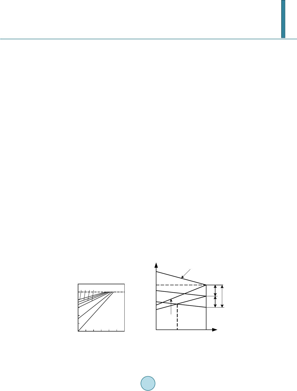 M. Y. Huang et al. laying equipment is particularly important because its imperfection directly affects stable operation of power system. Rectiformer is different from conventional transformers [1] for its protective applications must meet the re- quirements from rectifier bank. Because the valve side of rectiformer is always with multiple windings and large current, conventional current transformer cannot be installed. And the lack of special transformer’s differential protection algorithm poses difficulty for configuration of differential protection. Thus now rectiformer is in- stalled with gas protection as key protection of internal faults and the over-current protection [2]-[4] as coopera- tion. In recent years, large current measurement has become possible with advancement of research on digital cur- rent transformer, and this provides possibility to install differential protection devices. To improve the reliability of the rectiformer, a simulation model was built in this paper by PSCAD/EMTDC through research on phase- shift theory. The phase-shift transformer of special phase-shifting angle was one type of recitiformers, thus dif- ferential protection algorithm for any phase-shifting angle was deduced and verified aiming at the phase-shift transformer. 2. The Voltage Regulating Method of Rectif ormer The rectiformer needs larger adjusting range than the conventional transformers [5], the reasons are as follows: 1) The chemical and electrolytic industries commonly put workshops into operation in batches and stages as plan, and this causes that factory needs different voltages in varying stages, which is shown as in Figure 1(a). 2) When electrolytic cell starts, start-up current is much smaller than current needed in stable operation. It demands that rectifying installations have a large range of the output voltage to meet technological requirements, which is shown as in Figure 1(b). 3) In operation of electrolytic cell, constant power is needed. When power failure occurs, power operation happens or some cells quit running, the rectiformer’s voltage must be regulated as external characteristics of the electrolytic cell to keep normal production. This is shown in Figure 1(b ). 4) To adapt to fluctuation of voltage, the rectiformer must adjust its output voltage to maintain normal opera- tion of electrolytic cell. Therefore, rectifying installations mostly are equipped with on-load-tap-changing transformers, which makes rectiformer’s structure simpler. Phase-shifting function can also be added in if needed. The tap-changing autotransformer is widely used in rectifying installations, and it has three forms including the linear, the reversing change-over, the coarse fine voltage regulation. The autotransformer of the coarse fine voltage regulation is common in manufacture, and the schematic and wiring diagram is shown in Figure 2. copper electrolysis 100 80 60 40 20 100806040200 U d (%) 1 2 3 4 I d (%) aluminium electrolysis U d (%) U d max 100% U d H U d min ΔU 2 I s 100 Start-up currentI d (%) The characteristics of rectiformer Maximum cell number ΔU 1 ΔU (a) (b) Figure 1. Voltage regulation of rectification devices. (a) Electrolytic process requirement; (b) External characteristics of voltage regulation of electrolytic cell.  M. Y. Huang et al. (a) The positive fine-tuning (b) The negative fine-tuning Figure 2. Tap-changing autotransformer of the coarse fine voltage regulation. There are only two taps in winding of coarse-tuning, but multi coarse fine voltage regulation transformer can be built by adding taps to expand range of voltage if required. 3. The Transient Simulation of Phase-Shifting Transformer A model of rectiformer bank is built by PSCAD/EMTDC, and wiring diagram of one electrolytic aluminium factory is shown in Figure 3. The phase-shifting part of rectiformer adopts parallel operation of double four-winding transformers, which is shown in the schematic. The primary and second windings adopt dioptric wiring to shift phase, the third winding adopts two Y wirings, and the forth winding adopts two wirings, then end sinout putting 12 pulses to the rectifier cabinet. To reduce harmonic interference with power grid, electric power quality of DC bus must be ensured. In practice seven transformers with same norm but different phase-shifting angles are in parallel opera- tion, and their angles are , , , , , , respectively. Figure 4 was the model of rectiformer including the tap-changing, phase-shifting transformers and part of rectifier cabinet to DC bus. Above is the coarse fine voltage regulation autotransformer of 95 gears including 6 coarse gears and 16 fine gears. The model adopted on-load-tap-changing autotransformer to simulate tap-changing transformers, and the real- time adjustment of tap gear was achieved by Matlab and PSCAD (Figure 5). 4. The Deduction for the Differential Protection Algorithm of the Multi-Tap Transformers 4.1. The Differential Protection Algorithm upon Per Unit For on-load-tap-changing transformer, the transient response of primary and second voltage or current is ac- cording to location information of taps. Conventional differential protection is to set voltage and current’s change brought by variable ratio as unbalanced current for starting protection, and variable ratio is changing with tap in whole range of operation. However, sensitivity is lost while reliability meets requirement. Because on-load -t ap-changing transformer is selected as rectiformer whose range of current is quite large. The rated current varied from 5.8 A to 204.5 A based on ZHSFPTB-117000/330 transformer in this paper. Such a large range cannot slide over if set by unbalanced current, and misoperation must occur if information not in adaptive adjustment based on tap information. Therefore, differential protection algorithm of rectiformer must be in detailed setting aiming at tap position of on-l oad-tap-changing transformer. The tap information of recti- former contains transformation ratio information of rectiformer, so information of ratio can be obtained through tap gear information. What’s more, the internal transformation ratio parameters of the tap-changing transformer are changed in time and real-time calculation is adopted to ensure the differential protection correctly operate. Because of rectiformer’s large range of primary current and plenty of taps, current must be set aiming at all the taps if setting method of conventional transformer is adopted. The tap gears are numerous and the rated currents under various gears are different, so it will not only in- 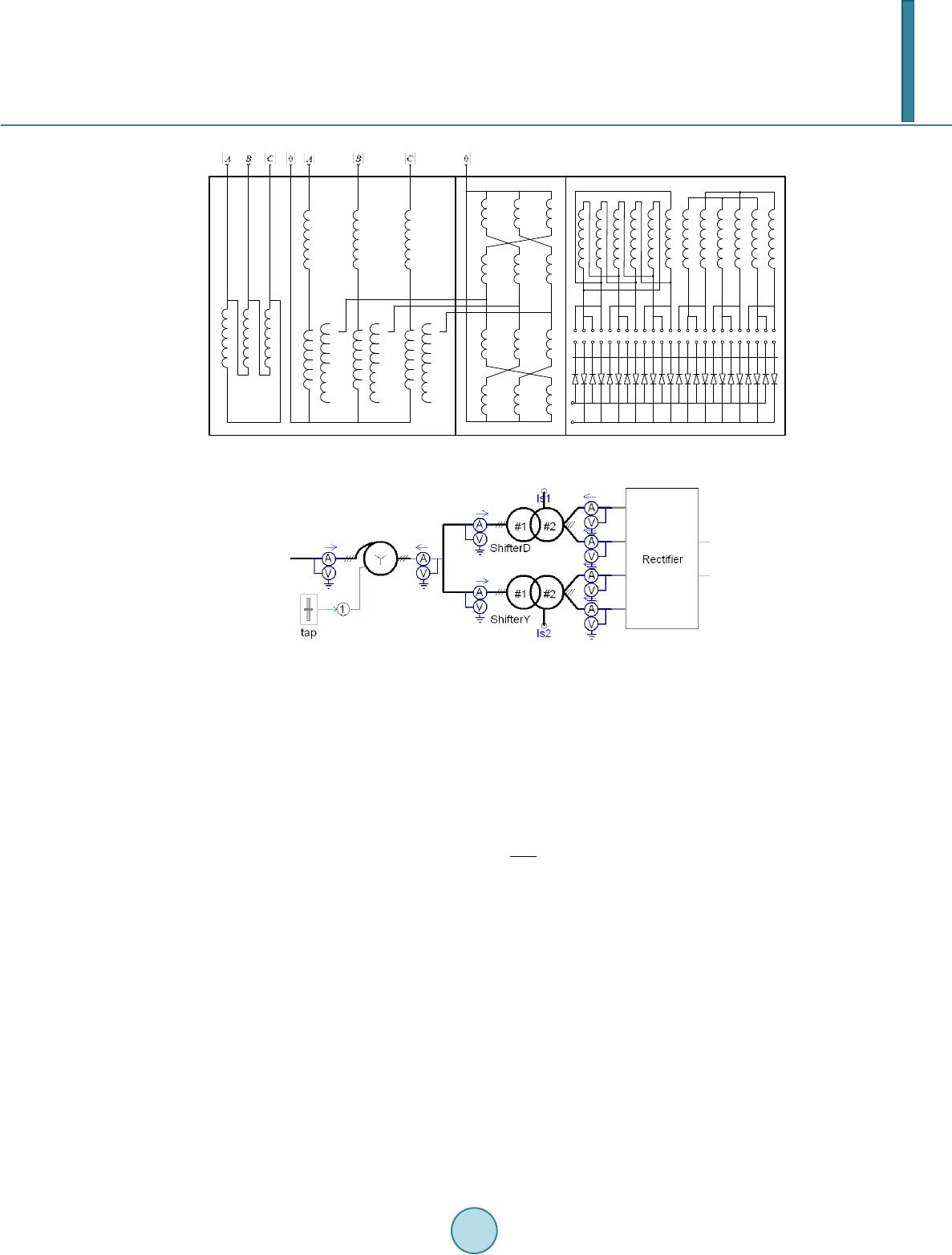 M. Y. Huang et al. ** * * 22 21 20 19 18 17 16 15 14 13 12 1 ** * 22 21 20 19 18 17 16 15 14 13 12 1 ** * 22 21 20 19 18 17 16 15 14 13 12 1 ** ** * ** * ** * ** * (+)Phase-shifting angle * * * * * ** * * * * * + - Figure 3. The wiring diagram of the rectiformer. Figure 4. The simulation model of the rectiformer. crease difficulty of protection setting but also add human involvement if all different gears’ rated currents set one by one. To avoid this and simplify protection algorithm, a new algorithm of differential protection upon per unit based on original algorithm was designed in this paper. With original basis upon rated current, the collected current data was divided by corresponding standard current in differential current calculation, and the differen- tial protection setting value was also calculated according to the per unit calculated upon the selected standard current. According to Equation (1), the calculation equation for differential current of the differential protection based on per unit is: 11 22 1 33 1 Wi N Wi iWi Wi Id I Id I Ib Id I = = ⋅ ∑ (1) Here is the standard current of the outlet wiring side of transformer. Choice of reference current is arbi- trary in theory, butto simplify the calculation and make multistage protections easily cooperate, rated current of the corresponding taps are supposed to be chosen as the standard currents of differential protection. The advantages of differential protection algorithm upon the per unit compared with the conventional algo- rithm upon rated value areas follows: 1) In the process of adjusting taps, the protection motion curve is consistent, which reduces the probability of the protection’s internal memory misoperation. 2) Calculating the transformer differential protection’s setting value for many times is avoided, and parameter errors brought by manual operation are reduced. 3) In the process of multistage protections cooperation, per unit value current of each protection can be di- rectly calculated, instead of being calculated many times upon the transformation ratio parameters. 4) For the same type of failure, its motion curve is consistent, which makes it convenient for the manufactur- ers and researchers to continue working. 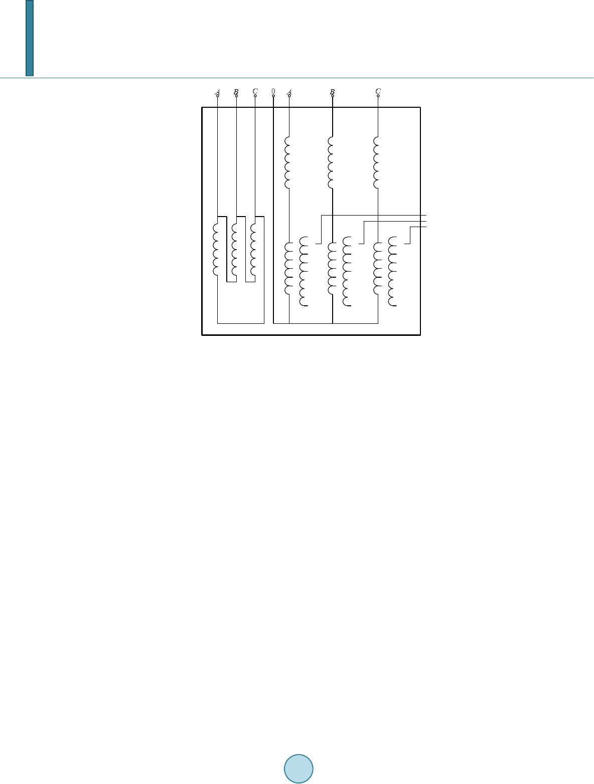 M. Y. Huang et al. ** * * 22 21 20 19 18 17 16 15 14 13 12 1 ** * 22 21 20 19 18 17 16 15 14 13 12 1 ** * 22 21 20 19 18 17 16 15 14 13 12 1 ** Figure 5. The simulation model of rectiformer. 4.2. The Differential Protection Algorithm Based on Per Unit Introducing the transformer tap information to the differential protection is equal to introducing new parameters to the original differential protection, whose correctness will determine the correctness of the differential protec- tion. Wrong tap information is likely to lead the differential protection to incorrectly operate even destroy the equipment, so related testing methods must be adopted to ensure the correctness of the tap gear information. When the tap gear information is incorrect, the alarm should start and the relay should be locked if in serious conditions. In order to ensure the correctness of the transformer tap gear information, a method of verifying the gear in- formation was proposed. After the verification of the transformer tap gear information, the differential protec- tion components should start and operate. The self-checking principles of the gear information are as follows: 1) The gear information is correct if continuously changing in bounds and three-phase gear’s difference is no more than three gear. 2) If the gear information not continuously changing, the alarm will keep warning until the stable gear infor- mation change. 3) The gear over bound (When gear information is greater than the maximum gear or equal to zero, the alarm will start and locking the relay). 4) When the gear’s difference of three-phase is greater than 3, alarm starts and locks relay. 5. The Validation of Special Transformer Differential Protection Algorithm Below was the oscillogram of the primary current and secondary current calculated by per unit when the tap- changing transformer was with different taps. From the comparative graphics (Figures 6-8), it could be seen that under different tap positions the current amplitudes were basically same on both sides after reduction, which meant a same curve of differential protec- tion operation could be used. However the unbalance current on both sides of the tap-changing transformer gradually increased with the declining of the tap, and the unbalance current with minimum tap should be set as the setting current of the protection. In magnetizing inrush current of transformer, the phase-shifting transformer is usually installed behind the tap- changing transformer, and only the per-stage transformer is equipped with the breaker. Thus the magnetizing in- rush current phenomenon only appears in the per-stage transformer but not the next phase-shifting transformer. 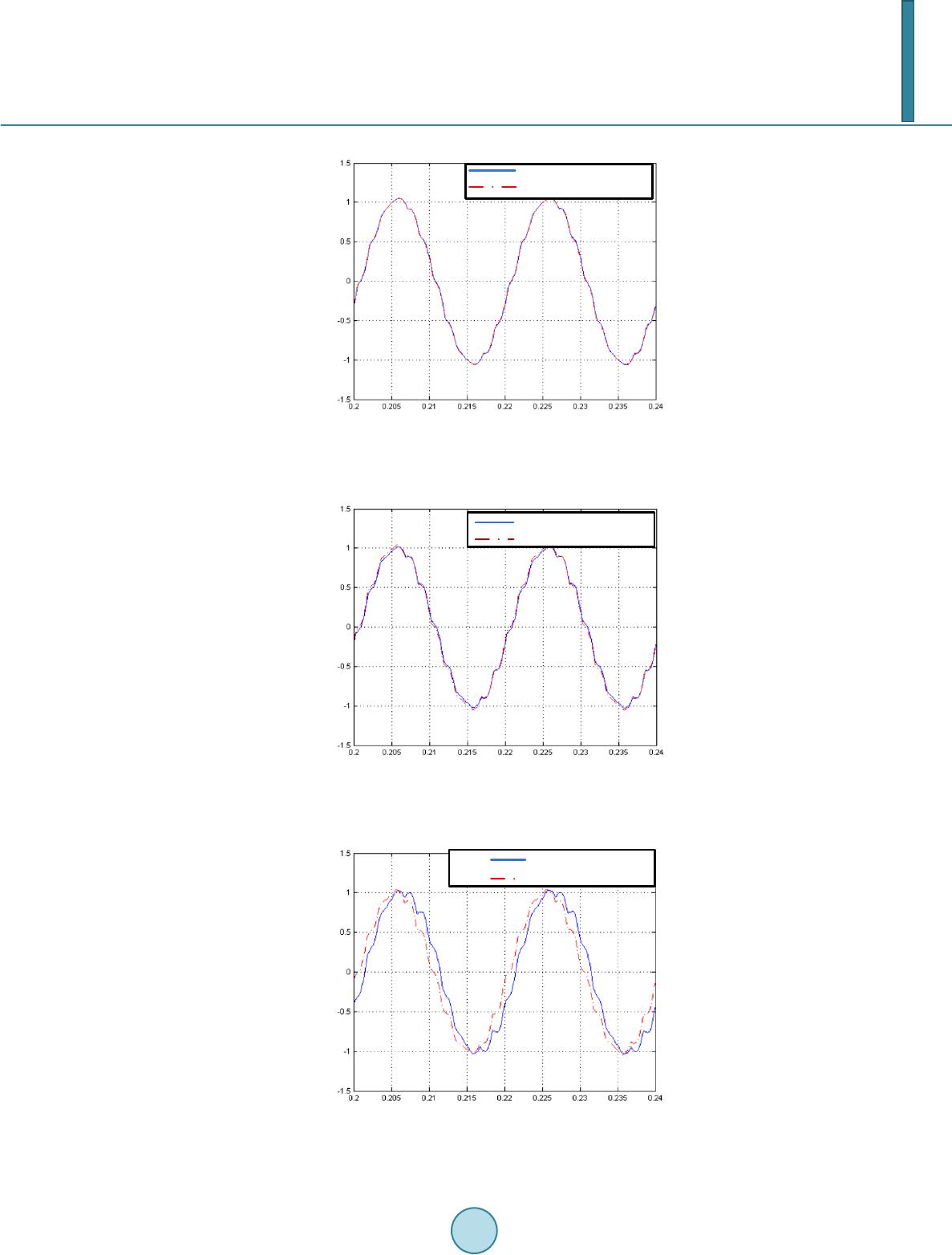 M. Y. Huang et al. The primary current of per unit The secondary current of per unit Figure 6. The current contrast of both sides in 96 gear. The secondary current of per unit The primary current of per unit Figure 7. The current contrast of both sides in 48 gear. The primary current of per unit The secondary current of per unit Figure 8. The current contrast of both sides in 1 gear. 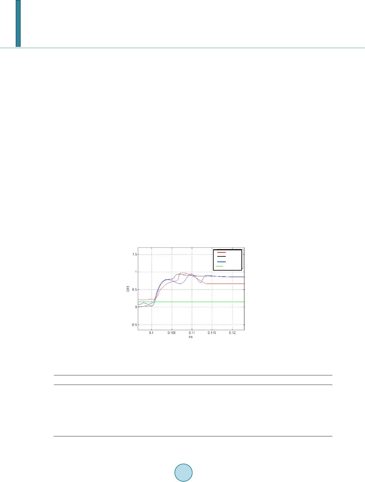 M. Y. Huang et al. Though rectifier circuit of rectiformer might bring high harmonics, second harmonic was almost zero in steady state because of the pulse number increasing. The second harmonic of tap-changing transformer was large when no-load closing happens, so the restraint method could be adopted to avoid inrush current just like conventional transformers. Figure 9 shows the second harmonic calculated after the magnetizing inrush current phenomenon happens in the tap-changing transformer in rectiformer bank. For a further validation of all the phase-shifting transformers’ differential protection algorithm performance, protection operation situations in all types of faults were simulated, including both the internal and external po- sitions of the tap-changing transformer. The simulation results were shown in Table 1 below. Because rectiformer adopts ungrounded neutral mode, and single-phase-to-earth short-circuit fault cannot be accurately identified. However, the differential protection algorithm can accurately identify internal and external faults, correctly operate. In this paper, through the establishment of transient simulation model of rectiformer, the differential protec- tion algorithm applied to multi-tap rectiformers is derived. Then the algorithm is verified and the following con- clusions are: 1) Due to the rectiformer’s special principle and connection form, the original conventional differential pro- tection algorithm for transformers cannot be adopted. An appropriate algorithm must be proposed according to the operating characteristics and special structure of the rectiformer bank. 2) Due to technical limitations, research on special transformer protection has not been taken seriously by scholars. The special transformer protection is technically mature in electric parameters along with development of digital transformer technology and construction of smart grid. But protection algorithm of special transform- ers also needs to be constantly perfect. According to the work in this paper, the algorithm suitable for the recti- former’s multi-tap has a certain application prospect. In this paper, the applicable conditions of differential protection algorithm with tap information were verified only in rated operation condition and the condition with inrush current. The next step needs more comprehensive Phase A Phase B Braking line Phase C Figure 9. The second harmonic of the tap-changing transformer’s magnetizing inrush current. Table 1. The operation of differential protection. System side Primary side Secondary side DC side Single-phase-to-earth short-circuit × √ × × Two-phase short-circuit × √ √ × Two-phase-to-earth short-circuit × √ √ × Three-phase short-circuit × √ √ × Three-phase-to-earth short-circuit × √ √ × *In this table, √ is correct operation, × is incorrect operation.  M. Y. Huang et al. simulations under all the operating conditions of rectiformer, which could provide more foundations to the re- search on the theory of special transformers. References [1] Hu, G.R. (2008) Structural Characteristics of Common Patterns of Rectifier Transformer. Transformer, 45, 7-12. [2] Wei, Q. (2011) Exploration of Roaster Exhaust Directly to Pre-Carbonation Decoomposition. Shanxi Metallurgy, 34, 39-54. [3] Geng, Q.L. (2007) Bang-Bang Protection of High Power Rectification Voltage Transoformer. China Chlor-Alkali, 6, 27-29. [4] Kang, T.Y. (2006) Protection of High-Power Rectiformer. Electric Time, 3, 74-75. [5] Cui, L.J. (1996) Theory and Design of Special Transformers. Scientific and Technical Documentation Press, Beiji ng.
|