 Journal of Power and Energy Engineering, 2014, 2, 57-63 Published Online September 2014 in SciRes. http://www.scirp.org/journal/jpee http://dx.doi.org/10.4236/jpee.2014.29009 How to cite this paper: Makhanlall, D. and Jiang, P.X. (2014) Thermodynamic Head Loss in a Channel with Combined Radia- tion and Convection Heat Transfer. Journal of Power and Energy Engineering, 2, 57-63. http://dx.doi.org/10.4236/jpee.2014.29009 Thermodynamic Head Loss in a Channel with Combined Radiation and Convection Heat Transfer Deodat Makhanlall, Peixue Jiang Department of Thermal Engineering, Tsinghua University, Beijing, China Email: deodat@mail.tsinghua.edu.cn Received July 2014 Abstract Losses in channel flows are usually determined using a frictional head loss parameter. Fluid fric- tion is however not the only source of loss in channel flows with heat transfer. For such flow prob- lems, thermal energy degradation, in addition to mechanical energy degradation, add to the total loss in thermodynamic head. To assess the total loss in a channel with combined convection and radiation heat transfer, the conventional frictional head loss parameter is extended in this study. The analysis is applied to a 3D turbulent channel flow and identifies the critical locations in the flow domain where the losses are concentrated. The influence of Boltzmann number is discussed, and the best channel geometry for flows with combined heat transfer modes is also determined. Keywords Radiation-Convection Heat Transfer, Thermodynamic Head Loss, Entropy Generation 1. Introduction Thermodynamic irreversibility reduces the efficiency of all practical momentum and heat transfer processes. The measurable effects of thermodynamic irreversibility in a flow through a channel are the drop in pressure and temperature. The non-measurable effects involve entropy generation. A loss in total head is thus related to en- tropy generation. This relationship can be written as [1]: (1 ) and shows that the friction head loss term in the energy equation is a measure of the thermodynamic irreversibil- ity associated with momentum transfer, i.e. mechanical energy degradation. In flows involving heat transfer, thermal energy degradation also occurs in addition to the mechanical energy degradation. The objective of this work is to use an extended form of Equation (1) to study both mechanical and thermal energy degradation in a 3D channel with combined radiation and convection heat transfer. Such flow problems are important in high-temperature applications, such as solar energy collectors, nuclear reactors, and 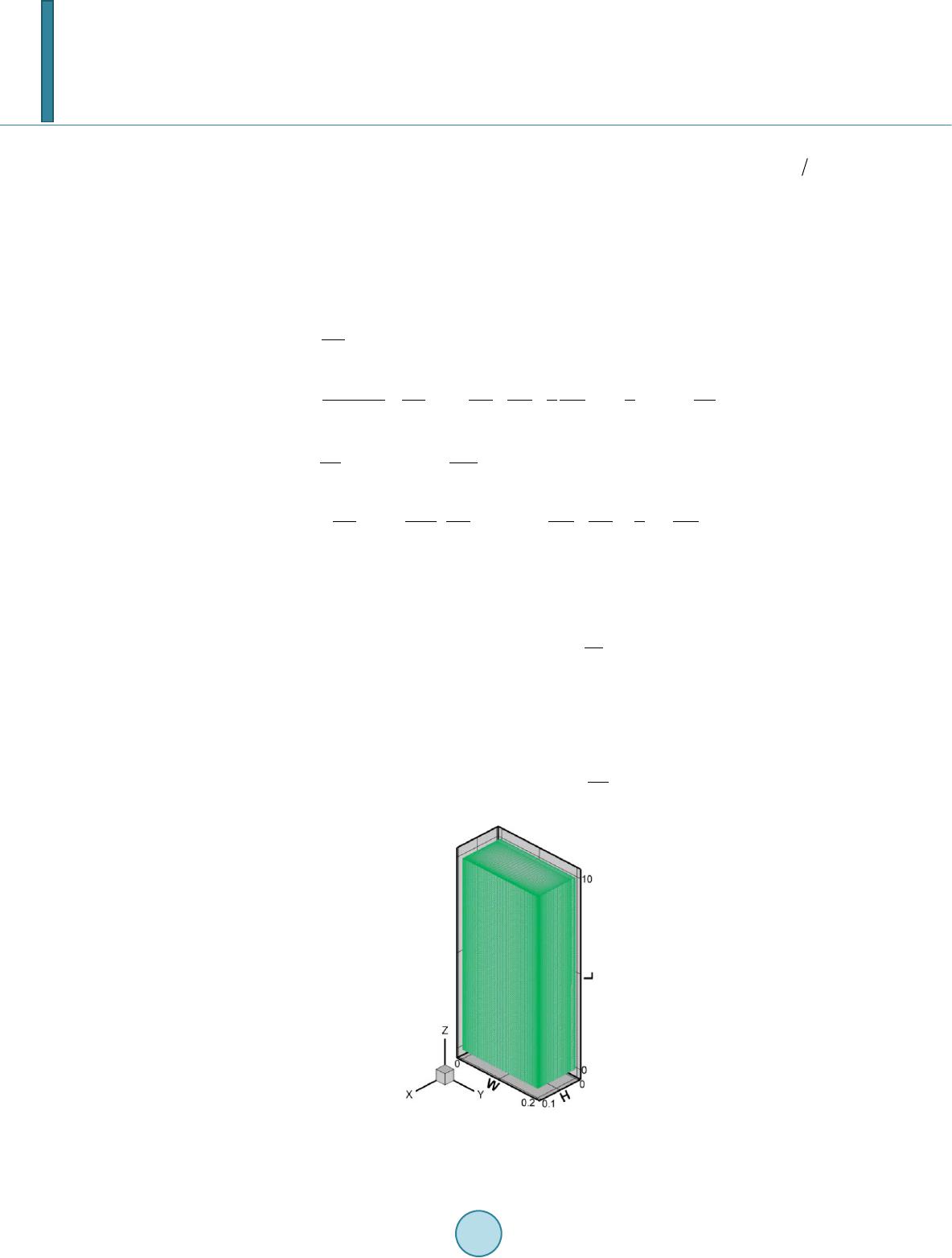 D. Makhanlall, P. X. Jiang electronic equipments. The FLUENT 6.3 CFD code is employed to solve the governing equations. The prob- lem schematic is shown in Figure 1 and consists of a 10 m long 3D channel with aspect ratio . Turbulent flow is considered. 2. Theory 2.1. Governing Equations The equations for mass, momentum and energy transfer in the channel can be written in Cartesian tensor form as following, respectively: (2) () eff 22 33 ij j ik ij ij jjji ki uu u uu p k xxxx xx ρµδ ρδ ∂ ∂ ∂∂ ∂∂ =+−− − ∂∂∂∂ ∂∂ (3) 0 2 eff eff 2 2 Pr 3 Ti ip T i ptj ik miij r j tjijk u uc dT x cu uu T ku xxxx x ρ ρ µµ µδ ∂+ ∂ ∂ ∂∂ ∂∂ =+++ −−∇⋅ ∂∂∂∂∂ ∫ q (4) where, is a velocity component, is the density, is thermal conductivity, is specific heat, is the turbulent Prandtl number, and and are the turbulent and effective turbulent viscosities, respec- tively. They are computed as following: (5) Here, is a model constant, is the turbulent kinetic energy, and is the turbulence dissipa- tion rate. and are determined by solving two additional transport equations [2]. Evaluation of the energy equation requires knowledge of the radiative intensity field. This is obtained by solving the radiative transfer equation (RTE), with its boundary condition for opaque surfaces [3]: ()( ) ( ) ( )() () 4 ,,, ,d 4 s aba s III I λλλλ π κ κ κκπ ′′ ′ ⋅∇=−++ΦΩ ∫ srsrrsrss s (6) Figure 1. Mesh view of the compu- tational domain.  D. Makhanlall, P. X. Jiang ( )( )() 1 , ,d w wwb ww II I λλ λ ε επ ′ ⋅ −′ ′′ = +⋅Ω ∫ ns rs rrsns (7) Here, and are the radiative absorption and scattering coefficients, respectively, is wavelength, is spectral intensity, λ is blackbody spectral intensity, is the scattering phase function, is solid angle, is a unit surface normal vector, is a unit position vector, is a unit direction vector, and is the wall emis- sivity. Once the intensity distribution is known, the radiative source term in the energy equation is computed as follows ( ) 04 4 dd r ab II λλ λ π κπ λ ∞ ∇⋅ =−Ω ∫∫ q (8) Solution parameters are presented in Table 1. 2.2. Thermodynamic Head Loss For channel flows in thermal equilibrium with the reference state at temperature heat transfer effects can be neglected, and viscous dissipation is the only irreversible process (electric and magnetic fields, chemical reac- tions, and other sources of irreversibility are not considered in this study). The frictional head loss in Equation (1) then gives an exact measure of thermodynamic irreversibility. However, for flows involving heat transfer, the fric- tion head loss is only a measure of mechanical energy degradation. When momentum and heat transfer (including radiation and convection) occur, a thermodynamic head loss can be introduced that include both mechanical and thermal energy degradations as following: (9) Here, , is the conventional head loss due to viscous dissipation, is the head loss due to heat conduction and convection, and is the head loss due to thermal radiation. These head loss terms can be computed as following (10) 0, 1d ccgen cc V hTSV m′′′ =∫ (11) ,, 11 dd aes w rgen rgen r VA hTS VTS A mm = + ∫∫ (12) The radiation term has two parts: the first part accounts for losses due to absorption, emission and scattering of ra- diation heat in the medium, and the second part are the losses that occur near solid surfaces due to wall radiation Table 1. Model parameters. Parameter Symbol Value Unit Density Specific heat Thermal conductivity Viscosity Turbulent prandtl number Absorption coefficient 0.5 Scattering coefficient 0.01 Scattering phase function Wall emissivity 0.9 Inlet temperature 1000 Inlet velocity 1  D. Makhanlall, P. X. Jiang absorption-emission processes. 2.3. Computation of Local Entropy Generatio n Rates The local entropy generation rates in Equations (13)-(16) are computed following procedures discussed in pre- vious studies: 1) For viscous dissipation in turbulent flow [4] (13 ) where, is the viscous dissipation function. 2) For heat conduction and convection in turbulent flow [4] 2 ,2 Pr pt gen ccmt cT Sk T µ ∇ ′′′ = + (14) 3) For radiation absorption, emission, and scattering in semitransparent medium [5] () ( ) ( ) ( ) () ( ) () ( )( )()() ,04 04 04 404 r,s r,s dd dd r,s r,s r,s Φs,s dddr,srd d 4 r,sr b aes r genasa b sa b II STT III TT λλ λλ λ ππ λλ λ λλ λλ ππ π λ κκλ κλ κκ λλ λ ∞∞ ∞∞ ′′′ =− +Ω+Ω ′′ +ΩΩ+− Ω ∫∫ ∫∫ ∫∫ ∫∫∫ (15) 4) For radiation absorption-emission processes at the solid walls [6] ( ) ,04 () ()dd w r gen I SL T λ λ π λ ∞ ′′ =− ⋅Ω ∫∫ www w r ,sr,sn s r (16) Here, ( )( ) { } 4 (,)21 ln1ln b L kc λ λ − =Γ+Γ+ −ΓΓ w rs (17) and (18) where, is Boltzmann’s constant, is Planck’s constant, and is the speed of light. The solvers in FLUENT are assigned a UDF (user defined function) for solving Equation (13) and Equation (14). Equation (15) and Equation (16) are solved with a FORTRAN 77 program. The solution methodology is discussed in [6]. 3. Results and Discussion Grid independence study was carried out to ensure that essential physics were not strongly dependent on grid size. It was assumed that maximum errors occurred in high-temperature-gradient and high-velocity gradient re- gions. The grid in the high-gradient regions was refined until the change in entropy generation rates were less than 1%. The final grid consisted of 200,000 cells with near-wall cell clustering. The mesh view is shown in Figure 1. Figure 2 shows cross-section slices and iso-surfaces of the computed velocity and temperature fields. The velocity field quickly develops into a small near-wall zone with strong gradients, and a much larger channel center zone with an almost uniform velocity. This is because of the low viscosity and no-slip boundary condition employed. The temperature field also quickly establishes a high temperature zone at the channel center, and a high-temperature gradient near-wall zone at the entrance region of the channel. The frictional and heat transfer head losses are shown in Figure 3. The velocity and temperature fields deter- mine how these losses are distributed in the channel. Losses due to heat conduction and convection are depend- ent on the local temperature gradients (see Equation (14)). The conduction and convection head losses are high 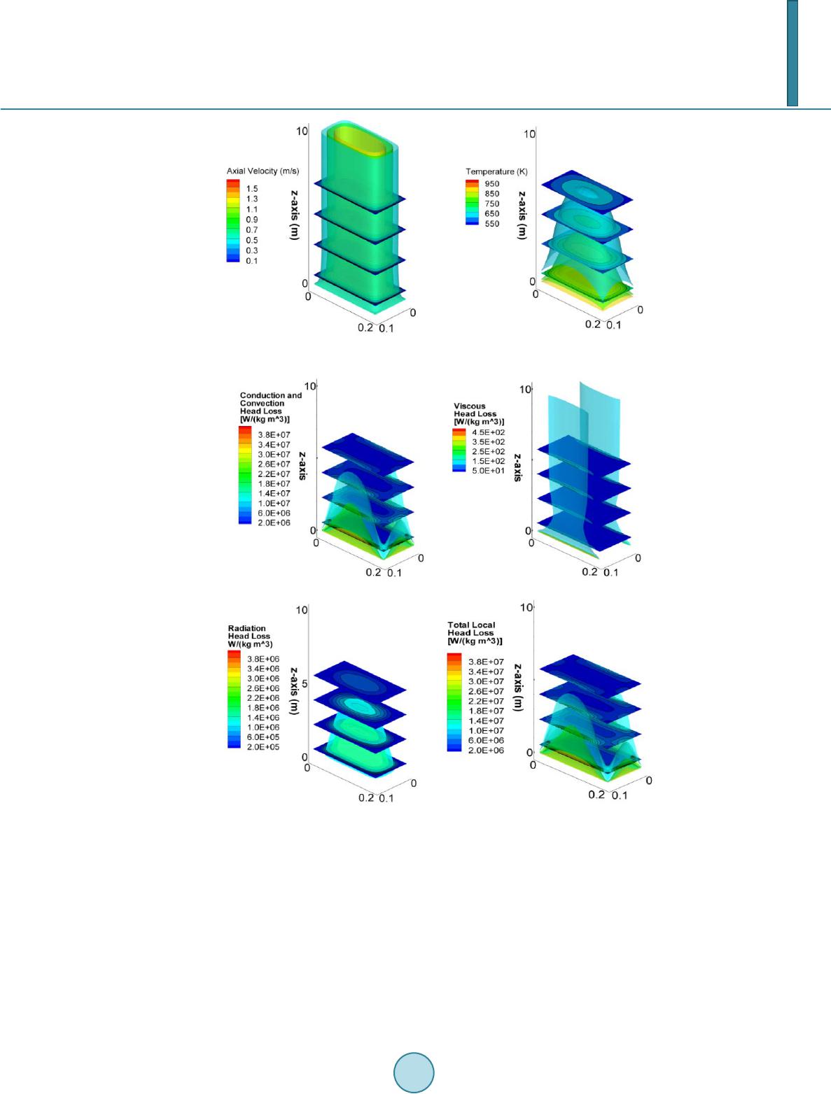 D. Makhanlall, P. X. Jiang Figure 2. The computed velocity and temperature fields. Figure 3. The computed local head losses. in locations with strong temperature gradients. Frictional head losses are significant in regions with high veloc- ity gradients. The high temperature and high velocity gradient regions are identified in Figure 2. These critical regions are located at the near-wall zone, mainly in the first half of the channel. In accordance, the head losses due to heat conduction and convection, and viscous dissipation are significant near the solid walls in the begin- ning half of the channel. While heat conduction and convection, and viscous dissipation are short-range phenomena, thermal radiation is a long-range phenomenon. Hence, the thermal radiation head losses are determined by the entire temperature field. In general, the radiation entropy generation is most important in high-temperature regions. Thus the radia- tion head losses are also relatively very strong at the channel center in the first half of the channel, where the fluid is hottest. 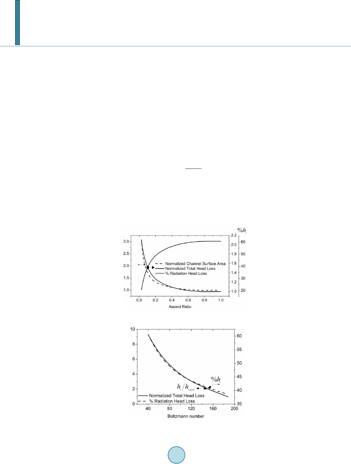 D. Makhanlall, P. X. Jiang Overall, the total head loss is for 50% due to heat conduction and convection. Radiation absorption, emission and scattering processes in the medium account for 30% of the total head loss, while wall radiation processes account for 20%. The total radiation effect is thus as important as that of heat conduction and convection in the high-temperature flow. Total loss in head due to viscous dissipation can be neglected. Viscous effects usually become important only when heat transfer effects can be neglected. It is important to notice that most of the head losses occur in the near-wall zone. Hence, thermodynamic op- timization of the channel flow should involve reducing the influence of this critical region. This can be achieved by reducing the wall surface area of the channel. The results, in which the channel aspect ratio is varied at con- stant channel volume, are shown in Figure 4. It can be seen that the total losses in thermodynamic head are minimize d in the channel with aspect ratio 1 (square channel). The square channel has the smallest surface area for a given channel volume, and thus the smallest critical near-wall zone. In the square channel, 60% of the total loss in thermodynamic head is due to thermal radiation. The radiation effects in the medium in this case are about 5% larger than that at the walls. A method to reduce the influence of radiation is discussed below. In combined radiation and convection heat transfer problems, Boltzmann number approximately represents the ratio of convection to radiation heat transfer. Boltzmann number can be defined as: (19) where, is the Stefan-Boltzmann constant. Since thermal radiation is the main irreversible process in the square channel, increasing Boltzmann number may reduce the overall losses in thermodynamic head. The parametric study showing the effects of Boltzmann number is presented in Figure 5. Both, the percentage radiation head losses and the total thermodynamic head losses, reduces with increasing Boltzmann number. Thus, in combined radiation and convection heat transfer, the thermodynamic losses are lower when the fraction of heat transported by radiation is reduced. Figure 4. Effects of channel aspect ratio. Figure 5. Effects of Boltzmann number.  D. Makhanlall, P. X. Jiang 4. Conclusions The conventional frictional head loss parameter is extended in this work to account for both mechanical and thermal energy degradation in flows involving heat transfer. The new head loss parameter is applied in the analysis of a 3D channel flow with combined radiation and convection heat transfer. The results show that: 1) Thermodynamic head losses in high-temperature flow occur mainly at the channel near-wall zone. 2) The size and influence of this zone is minimized in square channels. 3) Radiation head losses can be very strong in channels flows with combined radiation and convection heat transfer. 4) Large Boltzmann number should be selected for channel flows with combined radiation and convection heat transfer in order to reduce the total thermodynamic head losses. Acknowledgements This work is financially supported by Tsinghua University. References [1] Adeyinka, O.B. and Naterer, G.F. (2005) Entr opy -Based Metric for Component-Level Energy Management: Applica- tion to Diffuser Performance. International Journal of Energy Research, 29, 1007-1024. [2] (2006) FLUENT 6.3 User’s Guide. [3] Modest, M.F. (2003) Radiative Heat Transfer. 2nd Edition, Academic Press, San Diego. [4] Yapici, H., Kayatas, N., Albay rak , B. and Bas tur k, G. (2005) Numerical Calculation of Local Entropy Generation in a Methane-Air Burner. Energy Conversion and Management, 46, 1885-1919. [5] Caldas, M. and Semiao, V. (2005) Entropy Generation through Radiative Transfer in Participating Media: Analysis and Numerical Computation. Journal of Quantitative Spectroscopy and Radiative Transfer, 96, 423-437. [6] Liu, L.H. and Chu, S.X. (2007) Verification of Numerical Simulation Method for Entropy Generation of Radiation Heat Transfer in Semitransparent Medium. Journal of Quantitative Spectroscopy and Radiative Transfer, 103, 43-56.
|