Journal of Applied Mathematics and Physics, 2014, 2, 910-917
Published Online August 2014 in SciRes. http://www.scirp.org/journal/jamp
http://dx.doi.org/10.4236/jamp.2014.29103
How to cite this paper: Hajdas, W., Desorgher, L., Deiters, K., Reggiani, D., Rauber, Th., Tulej, M., Wurz, P., Luethi, M.,
Wojczuk, K. and Kalaczynski, P. (2014) High Energy Electron Radiation Exposure Facility at PSI. Journal of Applied Mathe-
matics and Physics, 2, 910-917. http://dx.doi.org/10.4236/jamp.2014.29103
High Energy Electron Radiation Exposure
Facility at PSI
Wojtek Hajdas1*, L. Desorgher1, K. Deiters1, D. Reggiani1, Th. Rauber1, M. Tulej2, P. Wurz2,
M. Luethi2, K. Wojczuk1, P. Kalaczynski1
1Paul Scherrer Institut (PSI), Villigen, Switzerland
2University of Bern, Bern, Switzerland
Email: *wojtek.hajdas@psi.ch
Received 3 June 2014
Abstract
Paul Scherrer Institut hosts the Proton Irradiation Facility used for radiation effects studies and
exposure tests in preparation of satellite missions for the European Space Agency. The facility al-
lows for realistic simulation of the space proton spectra in the energy range from 6 MeV up to 230
MeV with exposure fluxes ranging from very low up to as high as 109 p/cm2/sec. Recently, ap-
proved ESA mission to JupiterJUICE—also brought a need for tests with high energy electron
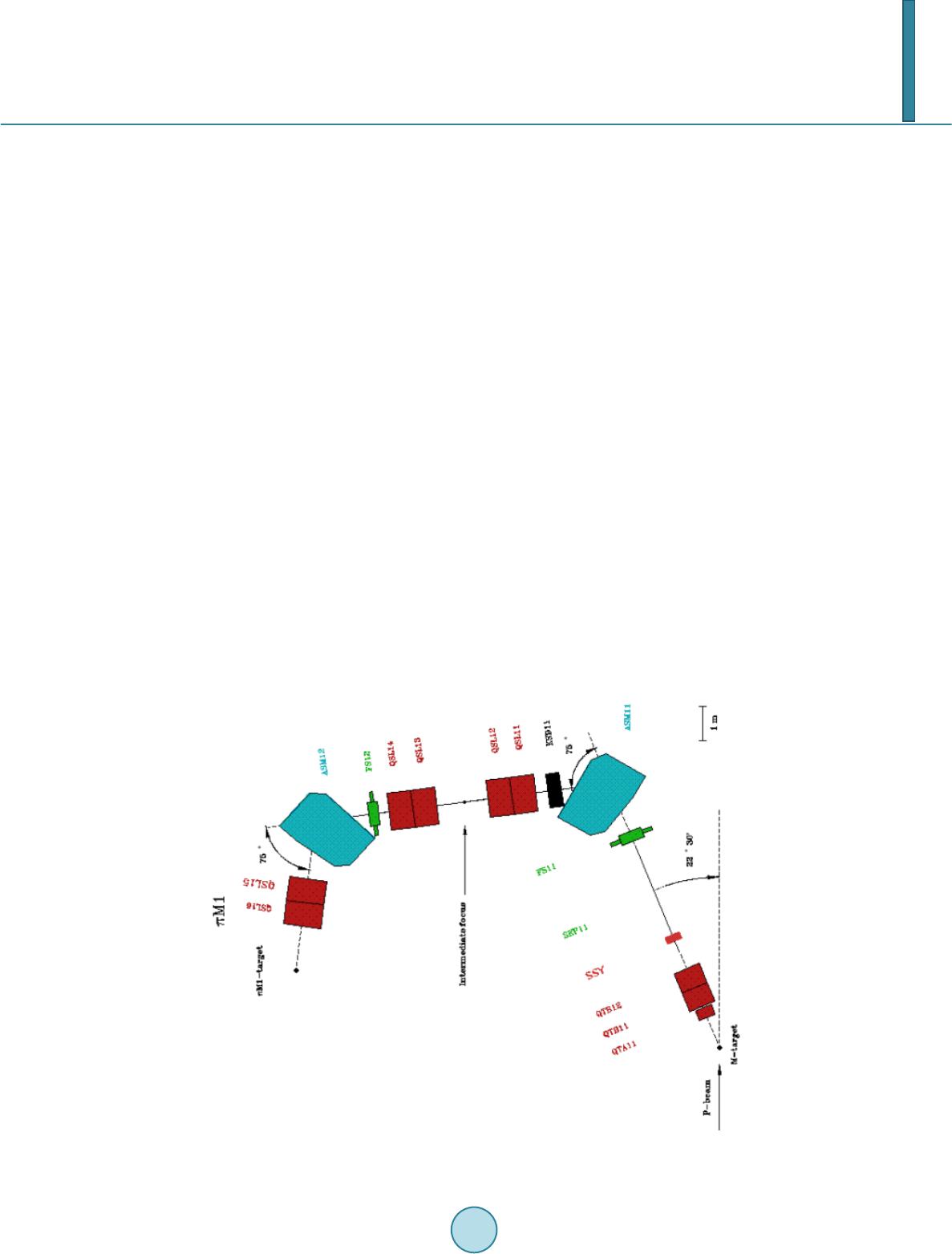
beams. For this purpose, another facility was established in the PSI secondary beam area piM1.
Secondary particles are produced on the thick carbon target hit by energetic proton beam. Dedi-
cated beam optics enables selection of the particle charge and momentum and guides them to the
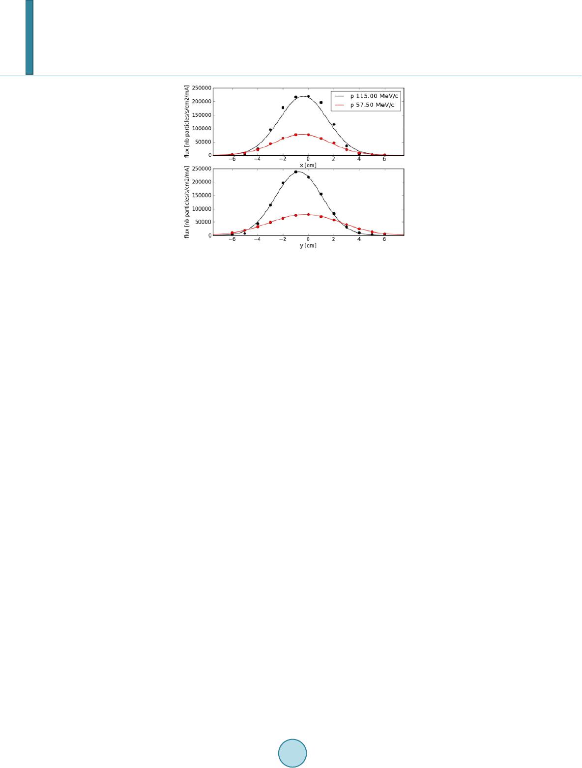
tests area. Characterization of electron beams at various momenta was performed with respect to
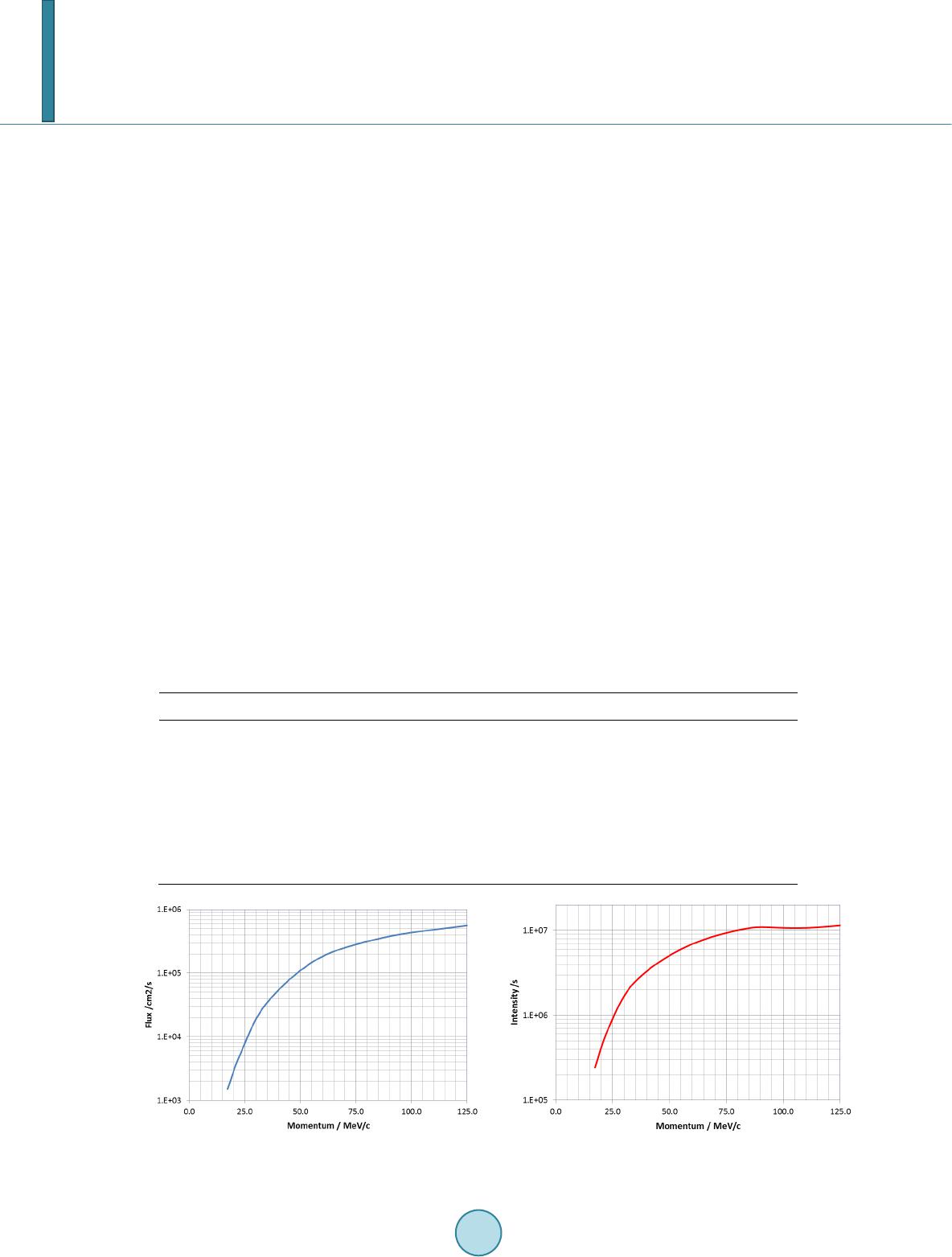
their intensity, profiles and contamination by pions and muons. Electron fluxes ranging from 1.5 ×
103/cm2/s at 20 MeV/c to 2.3 × 10 6/cm2/s at 345 MeV/c with gaussian beam profiles with FWHM
of about 4 cm were measured. Beam contamination with heavier particles becomes negligible for
all momenta lower than 115 MeV/c. This allows for using them for components and shielding cha-
racterization and detector calibration experiments. Several such experiments have been already
performed utilizing available beam time of few weeks per year.
Keywords
Irradiations, Electron Beams, Components Tests, Exposure Facilities
1. Introduction
Secondary beam experimental areas of PSI are mainly used for basic research tests with pions and muons. They
utilize 590 MeV, high intensity proton beam from the synchro-cyclotron and two carbon targets used to produce
secondary particles. Several beam lines were constructed and specialized in delivering of various secondary par-
ticles with respect to the type, charge and momentum. Design and complexity of each beam line influence such
beam parameters as particle intensity, range of its momenta and momentum resolution as well as contamination
*
Corresponding author.
W. Hajdas et al.
911
degree with other particle types. Although most of the experiments are devoted for studies of classic particle
physics problems, some of the recent activities also cover detector and shielding characterization tests for space
missions. An example of such mission is JUICE planned to be sent by the European Space Agency to Jupiter for
studies of its icy moons and search for life-friendly inhabitants. Radiation environment of Jupiter is especially
severe and not well characterized yet. Values of absorbed total dose expected within the JUICE mission lifetime
are bigger than 1 Mrad (Si) while anticipated energies of trapped electrons are even higher than one hundred
MeV. It poses a great challenge to all subsystems and components of the spacecraft even if they are categorized
as radiation resistant for standard missions around earth. Therefore, qualification of them for JUICE requires
dedicated and extended studies. In particular, instruments concept, operating conditions, quality of shielding and
performance of any detection system onboard, also including radiation monitors, must go through careful veri-
fication and optimization. It also requires new exposure facilities available for at least several weeks per year
and able to deliver electron beams with energies and intensities enabling for instrument tests in mission
semi-realistic or anticipated conditions. The piM1 secondary experimental area of PSI was selected for this pur-
pose. Its beams were precisely characterized and optimized for future experiments dedicated to space research.
All steps leading to the facility characterization and commissioning are described in the following chapters.
In the first step, the existing infrastructure is outlined and all optimization measures for detection of electrons
are detailed in chapter 2. Several measurements using dedicated experimental techniques and including opti-
mized arrangement for user test systems are described in chapter 3. They include studies of electron beam and
separation of other particles. Experimental results and characteristics of the available test beams are provided in
chapter 4. The last chapter 5 contains concise summary and future plans.
2. Secondary Beam Area piM1
Secondary particles for the Large Research Facilities at PSI are created by protons passing through 2 mm thick
graphite target located in the main beam-line of the PSI synchro-cyclotron. High energy and intensity of the
primary proton beam, 590 MeV and 2 mA respectively, allows for very efficient production of mainly pions,
muons but also electrons. The beam of secondary particles enters the path to the piM1 area at the angle of 22.3
degree with respect to the initial proton beam. The piM1 area layout is shown in Figure 1 [1]. Its selection for
space experiments was based on the spectral characteristics of its pion and muon beams with their intensity
Figure 1. Layout of the beam-optics for the piM1 beam 0 line.
W. Hajdas et al.
912
dropping strongly towards lower energies as well as on the easier accessibility for the users conducting short
duration experiments. The full beam optics of piM1 consist of two bending magnets ASM (75 degree each), one
quadrupole triplet QTA and QTB1/2 and three systems of quadrupole doublets: QSL1/2, QSL3/4 and QSL5/6.
The beam-line also contains two systems of slits FS1 and FS2 used to reduce beam intensity and improve its op-
tics. One is placed in front of the first bending magnet and the other is positioned in the air-gap located in front
of the second bending magnet—see figure below for details.
This air-gap is also used for placement of an additional energy degrader needed to differentiate momenta of
various incoming particles as a result of their specific energy loss. Such degrader can be for example used for
momentum separation between positive pions and protons resulting in different deflection of them by the fol-
lowing bending magnet. Magnet settings allow for selection of particle momenta up to 500 MeV/c while the
momentum resolution of the whole system can be as good as 0.1%. The charge of transmitted particles can be
chosen by direction of magnetic field in the bending magnets. The focal point of the beam is located in the air
about 150 cm behind the exit window of the last quadrupole magnet. One can reach typical beam widths of 4 cm
to 12 cm of FHMS. The total length of the beam-line from the production target to the focal point is equal to
about 24 m. Beam optics settings are loaded into the system automatically. For pre-defined setup any change of
the particle momentum can be completed within a very short time. PiM1 area is equipped with various cable
connections (BNC, HV, network, etc.) to the measurement barrack located about 10 m away. Users can also re-
lay on standard equipment such as high voltage power supplies, XY-table and beam scanners provided by the
beam-line scientist crew.
3. Experimental Setup
Experimental setup in the piM1 area was tailored for measurement of the electrons. It consisted of the parallel
plate ionization chamber located directly behind the beam exit window and the E-E plastic scintillator tele-
scope placed at the beam focal point. Dimensions of the E thin plastic were 30 × 30 × 2 mm3 while the cylin-
drically shape E-detector had thickness equal to 30 mm and 28 mm diameter. The space between both detectors
was less than 5 mm. Additional NaI (Tl) scintillation detector with the crystal size of one inch diameter and one
inch thickness was used for gamma-ray detection. For measurements of the beam profile the telescope was re-
placed by small (5 mm diameter) plastic scintillator mounted on the XY-table. The full setup is shown in Figure
2.
Figure 2. Experimental arrangement in the piM1 area.
W. Hajdas et al.
913
Detector system was connected with the readout electronics located in the measurement barrack placed sever-
al meters away from the area. For the ionization chamber the readout consisted of the high precision pico-am-
perometer with the current to voltage converter and current to frequency converter followed by the counter.
Plastic telescope was read out using linear (analogue) fan-in followed by amplitude discriminators, logical coin-
cidence unit and counters on one side and a high speed oscilloscope for the signal wave detection and analysis
on the other. This instrument also allowed for analysis of the detected pulses and building of histograms from
either signal amplitudes or time differences between two signals. Such data could also be stored on the disc for
furt he r analysis. The NaI (Tl) detector was read out by a system of preamplifier, amplifier and the multi-channel
analyzer. Small scintillator on the XY-scanning table was connected to the discriminator and counter. It was also
coupled with the XY-table control system enabling for automated measurements of the beam profiles. Beam
normalization was done using additional information provided by the cyclotron control and monitoring system.
All high voltage power supplies for above detectors were located directly in the piM1 area with a remote control
by the experimentalists from the barrack. Initially all detectors were calibrated with radioactive sources.
Experimental arrangement for the users also allowed for easy settings of their apparatus and devices. Experi-
ment alists had access to the tables and stages as well as additional shielding blocks made of either copper or
other materials. Results from the first user tests are presented elsewhere [2].
4. Measurement Results
4.1. Beam Profiles
Beam profiles were measured with the small plastic scintillators of 5 mm diameter fixed on the XY-table. The
system was located at the beam focal point. Vertical and horizontal scans were performed for eight momentum
values in the range from 17 MeV/c to 34 5 MeV/c. Two examples for momenta of 57 MeV/c and 115 MeV/c are
shown in Figure 3. All profiles could be well described using Gauss-function shape. Fitted values of FWHMs
are presented in Table 1. One can see that the profiles become wider at lower momenta. In the relevant range
from 115 MeV/c to 17 MeV/c the FWHM values increase from 4.4 cm at the highest up to almost 12 cm at the
lowest momentum. Such enlargement can be explained by higher probability of electron scattering at lower
energies, either in air or at the entrance and exit windows of the beam optics system. It was also observed that
the position of the horizontal beam center is relatively momentum independent and remains constant within
about 2 mm. The center in the vertical direction may change however by up to about 1.5 cm. Further tests and
beam optics studies are planned to explain this behavior.
Table 1. Relative contribution of electrons, muons and pions to the piM1 particle beam.
Momentum MeV/c Electrons TOF Pions TOF Muons TOF Electrons en. loss Pions en. loss
17.25 100.0 0.0 0.0 100.0 0.0
23.00 100.0 0.0 0 .0 100.0 0.0
34.50 100.0 0.0 0.0 100.0 0.0
57.50 100.0 0.0 0.0 100.0 0.0
86.25 100.0 0.0 0.0 100.0 0.0
115.00 9 7.5 1 .9 0 .7 100.0 0.0
143.75 83.8 14.2 2.1 8 2.8 17.2
172.50 63.2 34.5 2 .4 6 4.0 36.0
201.25 4 6.4 51. 4 2.2 4 4.2 55. 8
230.00 30.4 69.6 0 .0 2 2.8 77. 2
W. Hajdas et al.
914
Figure 3. Example of electron beam profiles measured for
two momentum values.
4.2. Pion and Muon Fraction of the Beam
Two methods were used to determine which types of particles composed the beam at each momentum. In the
time of flight method (TOF) the flight time of particles was measured with respect to the accelerator radio-fre-
quency signal. The start signal was provided by the small scanning detector placed during measurements at the
distance of 80 cm upstream from the focal point or roughly 23 m from the production target. The stop signal was
coming from the 50 MHz frequency of the synchro-cyclotron. This signal caused 20 nsec long periodicities in
measured TOF histograms. An example of two TOF spectra for momenta equal to 172 MeV/c and 230 MeV/c is
presented in Figure 4.
For each momentum three well distinguished peaks can be observed. As for all used momenta the electrons
travel with almost the speed of light their position in the spectrum remains unchanged—see peaks centered
around 0 ns value in figure. The speed of pions and muons is strongly momentum dependent. It is also well seen
that positions of their peaks are shifted. Relative distance to the electron peak can be verified in calculations us-
ing particle momentum, its mass and the trajectory length. This allows for assigning of the peak either to pions
or muons as well as, from integrated peak intensities, determination of relative contribution of specific particle
to the total beam intensity-see Table 1 for results. As the peaks are not only well separated but the space in-
between is free of background events, the gamma-ray contamination of the beam is relatively low.
In the second method, the particles were identified using their energy loss in the thick plastic scintillator of the
E-E telescope. An example of the spectrum measured at 172 MeV/c is shown in Figure 5. Although one can
see two peaks, their separation is not as good as in the time of flight method mainly due to the insufficient de-
tector thickness. To separate the peaks and find their relative contributions one performed fits of the Vavilov
function-see the red curve in figure. In the first step the fits were done to the spectra of pure electrons i.e. for
momenta smaller than 100 MeV/c. After normalization of this function to the electron peak maximum for the
spectra with double peaks, the contribution of other particles was found by subtraction. Due to limits in energy
resolution, this method was not able to provide any information on the muon presence in the beam especially as
their fraction was of the order of a few percent at the maximum.
Nonetheless, using above method of analysis gives the results that agree with measurements with the time of
flight method on the level of less than 10%. This discrepancy is comparable to experimental errors depending on
statistical accuracy, energy resolution and fit quality. However, the energy loss measurement is considered only
as a supporting measurement and for further use the TOF data should be taken.
Relative beam contributions from different particles are shown in Figure 6 in which the results from both se-
paration methods are presented. One can see that electron spectra with momenta up to 100 MeV are virtually
free of any pion and muon contamination. Above results also agree with previous measurements done for the
MUSE experiment [3] with respect to the electron fraction in the beam. Some differences are seen for the rela-
tive distribution between pions and muons at higher energies. Although irrelevant for electron beam this issue is
subjected to further investigation.
W. Hajdas et al.
915
Figure 4. Time of flight spectra measured at two different momenta.
Figure 5. Spectrum of energy loss measured by the thick detector of the tele-
scope at momentum 172 MeV/c.
Figure 6. Relative contributions of electrons, muons and pions to the piM1
particle beams.
It is also possible to reduce the non-electron fractions in the beam for momenta higher than 100 MeV/c. The
most efficient way is using of the electrostatic separator deflecting particles depending on their mass. Such de-
vices are at the moment installed in other secondary beam areas of PSI. For experiments requiring higher mo-
W. Hajdas et al.
916
mentum pure electron beams such area may be accessible upon approved user proposal and beam request.
Another method of removal is based on utilization of the energy degrader in the beam. It reduces and differen-
tiates momenta of passing particles. By proper tuning of the deflecting magnet placed further downstream, de-
sired particle type can be selected while the others will be removed from the beam-line. This method was suc-
cessfully tested using positively charged beams and separating protons from positive pions at momentum values
of 350 MeV/c.
4.3. Electron Fluxes
Electron fluxes and intensities were measured using small plastic scintillator on the XY-table. Measurements
were performed at the focal point of the beam. The main proton beam current was also measured in parallel for
normalization purposes. The full intensity of the secondary beams in the area was measured using the same me-
thod and by applying beam scans. The intensity value was obtained by integration of the scanned profiles over
vertical and horizontal directions. Both results are presented in Figure 7. They are given for the maximum pro-
ton beam current of 2.1 mA. Data presented in Table 2 are given for the normalized 1 mA value of the proton
current. As one can see the electron intensity rises with the momentum and becomes relatively constant at the
value of about 75 MeV/c. The increase is relatively smoothone order of magnitude from 25 MeV/c to 75
MeV/c. The electron flux shows different behavior and is characterized by much faster changes with momentum.
It is caused by additional enlargement of the beam profiles and increased scattering in air towards lower mo-
mentum. It gives the maximum flux at 25 MeV/c to be only about 104/cm2/s.
Having the piM1 beam-line fully contained in the vacuum would largely reduce electron scattering as two
thick windows and air-gap of about 2 m in length would be removed. It would result in higher fluxes and smaller
profiles at low energies. Such the modification of the beam-line is however not foreseen for the near future.
Therefore lower energy beams are mostly useable for tests of shielding penetration and detector calibration but
not suitable for total dose studies at high dose rate values.
As some experiments need to work with even lower intensities one can provide them by reducing the opening
of the beam line slits. This way the electron flux can be reduced to very low values. The total beam intensity can
Table 2. Electron beam parameters in piM1 area.
Momentum MeV/c Intensity s/mA Flux cm2/s/mA FWHMx cm FWHMy cm
17.3 1.16 E +05 7 .21 E +02 10.4 13.2
23.0 3.28 E+ 05 2.57E+03 9.0 12.9
34.5 1 .16 E +06 1 .56 E +04 6.6 9.6
57.5 3.08 E +06 7 .88 E +04 5.2 6.6
86.3 5.13E+06 1.69 E +05 4.2 5.1
115.0 5.18 E +06 2 .42 E +05 4.4 4.3
Figure 7. Maximum values of the electron flux and intensity for proton beam intensity of 2.1 mA.
W. Hajdas et al.
917
be monitored with the ionization chamber usually placed at the exit of the bam from the last quadrupole. It is
however necessary to perform flux and profiles measurement anew as the beam optics is changed with each
modification of the slit openings.
5. Summary and Conclusions
Secondary beam area piM1 in the Experimental Hall at thePaul Scherrer Institut was selected to test and charac-
terize electron beams of high momenta. The goal was its possible use for components exposures and instrument
testing for space applications. It was found that with existing beam optics the electron beams are free of other
particle contamination on the level of much less than 1% for momentum values up to about 115 MeV/c. Relative
contamination of the beam by secondary gamma-rays was also found to be on a very small level. Therefore the
area fulfills the criteria for providing electrons within energy range suitable for e.g. missions flying to Jupiter
such as JUICE. The maximum beam fluxes vary from about 103/cm2/s at momentum value of 17.5 MeV/c up to
4 × 10⁵/cm2/s at 155 MeV/c. Beam profile FWHM also shows momentum dependence changing from about 12
cm at the lowest to about 4 cm at the highest momentum values.
The piM1 area provides various equipment and utilities for the users such as cable connections, basic power
supplies and electronics infrastructure as well as movable stages and numerous shielding arrangements. Further
studies of beam parameters are ongoing, including characterization of the positively charged beams and deter-
mination of the beam proton fraction. In addition, measurements of gamma-ray and electron spectra behind pre-
defined shielding as well as verification of the collimator parameters at various initial electron energies are be-
ing performed.
The area is planned to be used for further space experiments aimed for space mission related studies such as
shielding optimization, performance characterization of instruments in presence of high energy electron back-
ground as well as calibration of detection syst ems.
References
[1] Deit ers, K. (2013) piM1 Beamline. http://aea.web.psi.ch/beam2lines/beam_pim1.html
[2] Tu l e j , M., et al. (2014) August 2014 submitted to nuclear instrument and methods.
[3] M. Kohl for MUSE Collaboration (2014) M uon elastic scattering with MUSE at PSI. EPJ Web of Co n feren ces 66,
06010.