 Journal of Computer and Communications, 2014, 2, 45-52 Published Online September 2014 in SciRes. http://www.scirp.org/journal/jcc http://dx.doi.org/10.4236/jcc.2014.211006 How to cite this paper: Ngetha, H., Sasaki, M., Tamagawa, H., Ito, S. and Ikeda, K. (2014) Dynamic Characteristics of Sele- mion CMV-Based IPMC Actuators in High Humidity Environment. Journal of Computer and Communications, 2, 45-52. http://dx.doi.org/10.4236/jcc.2014.211006 Dynamic Characteristics of Selemion CMV-Based IPMC Actuators in High Humidity Environment H. Ngetha1, M. Sasaki1, H. Tamagawa1, S. Ito1, K. Ikeda2 1Department of Mechanical Engineering, Faculty of Engineering, Gifu University, 1-1 Yanagido, Gifu 501-1193, Japan 2Graduate School of Advanced Mathematical Sciences, Meiji University, 4-21-1, Nakano, Nakano-ku, Tokyo 165-8525, Japan Email: sa sak i@gi fu -u.ac.jp Received Ju ly 2014 Abstract Electrically-induced bending of Selemion IPMC is caused by the charge induced into the IPMC. This induced charge quantity is susceptible to the absolute humidity of environment. There are two types of charges, the charge causing bending and the rest of charge tha t c auses no bending. In the high humidity environments, where absolute humidity is above 10 gm−3, the quantity of charge causing no bending accounts for the large part of whole charge induced into the Selemion IPMC, while quantity of such charge is negligibly small at the absolute humidity of less than 10 gm−3. Es- timating the quantity of those two types of charges individually, we successively analy zed the bending stability of Selemion IPMC at the absolute humidity above 10 gm−3. Consequently, we de- duced the following conclusions. 1) There exists a large time delay in the current in response to the voltage input, 2) Current is highly dumping, and 3) Bending behavior is marginally stable un- der the input of any frequency. Keywords IPMC, Selem ion-CMV, Open Loop Systems, Electric circuit Model, Compen sato r, MATL AB 1. Introduction Electrical control of IPMC bending (IPMC: Ionic Polymer-Metal Composite) is fundamentally, an important task for achieving a practical actuator of IPMC. It was previously elucidated that the bending controllability of IPMC was significantly improved by the dehydration treatment of the IPMC [1]: The bending curvature of highly dehydrated IPMC became basically proportional to the total charge imposed on it (Note: The IPMC was in the highly dehydrated state and not in the fully dehydrated state). It is assumed that the control of charge quantity imposed on the IPMC leads to the control of IPMC bending. Previously, the assumption was, in fact, confirmed experimentally [2]. However, on further scrutiny of IPMC bending behavior resulted in an indication that, the IPMC bending characteristics in the highly dehydrated state was not as simple as hypothesized by the  H. Ngetha et al. proportionality between its curvature and charge imposed on it. Three of the authors of this paper, Ikeda, Sasaki and Tamagawa, previously investigated Selemion CMV- based IPMC [3], where the Selemion CMV is one of ion exchange membranes manufactured by Asahi Glass Co., Ltd. (Tokyo). The Selemion CMV-based IPMC was approximated by an electric circuit consisting of capacitors and resistors (RC circuit). It was suggested that the quantity of charge flowing through the circuit played fun- damental roles of determining bending curvature. Such an assu mption was validated by the conclusions derived in the previous works [4]-[6]. But the three of the authors further suggested that that the individual charges flowing through resistors and stored in capacitances have individually distinctive influence on the bending in- duction [3]. Therefore, for the precise prediction of Selemion CMV-based bending behavior, it was necessary to estimate the individual charge quantities. According to the circuit model, there exists a certain quantity of charge, which flows through the Selemion CMV-based IPMC. This charge has no influence on the bending induction at all. However the rest of the charge had a quite significant influence on the bending induction. Fortunately, the influence of former type of charge, displaying no influence on the bending induction, was almost negligible at the environmental absolute humidity of lower than 10 gm−3, since its quantity was quite small, and theoretical prediction of Selemion CMV-based IPMC bending curvature was not so complex [7]. However, the prediction of the bending behavior at environmental absolute humidity above 10 gm−3 becomes quite complex, since the quantity of charge displaying no influence on the bending induction is not that negligibly small [7]. Hence, it is necessary to precisely estimate the quantities of both charges displaying no influence and the significant influ- ence on the bending induction. This makes the theoretical prediction of Selemion CMV-based IPMC bending less in complexity. The same is true for the stability analysis of Selemion CMV-based IPMC bending. Bending stability analysis was relatively simple, as long as we considered the bending of Selemion CMV-based IPMC in the environment with the absolute humidity lower than 10 gm−3. However, the process is somehow complex, when the absolute humidity is above 10 gm−3. In this paper, we present the result of the bending stability analysis of Selemion CMV-based IPMC in the en- vironment with the absolute humidity above 10 gm−3. 2. Selemion CMV-Based IPMC Actuator 2.1. Specimen Preparation First, we fabricated Selemion CMV-based IPMCs, hereafter referred to as Selemion IPMC. Then we carried out bending tests of Selemion IPMC to acquire the time course of bending curvature of Selemion IPMC and current induced in it under the influence of voltage application as a function of time. Selemion CMV surface was roughened using sandpaper. Debris on the Selemion CMV surface was washed off with water. Then it underwent silver plating process by the silver mirror reaction. Silver plating process was repeated four times in totality for the secure silver plating. On completing of silver plating, the Selemion CMV was immersed in water to wash off any remnants of the debris on surface. The resultant silver-plated Selemion CMV was the Selemion IPMC. It was stored in the vacuum state in desiccator with desiccant. 2.2. Bending Analysis A thin sheet of Selemion IPMC was cut into strips, 20 mm in length and 2 mm in width. Though it had been stored in the vacuum state so as to be dehydrated, it needed to contain a minute quantity of water to be activated under electrical stimulation. Therefore, before carrying out bending tests, Selemion IPMC strips were left in the atmosphere for at least 30 minutes so that they could absorb a minute quantity of water from the environment. After the exposure of Selemion IPMC to the environment, the Selemion IPMC was clamped horizontally with a pair of electrodes. Experimental setup employed was exactly the same as that employed in the ref. [3]. A vol- tage was imposed on the Selemion IPMC in the humidity and temperature controlled environment, where the absolute humidity was constantly maintained at above 10 gm−3. Selemion IPMC vertical displacement and cur- rent induced through it were measured as a function of time using a laser displacement sensor and an ammeter, respectively. 3. Circuit Model Ikeda et al. built a circuit model of the Selemion IPMC for predicting the bending behavior. The model built, 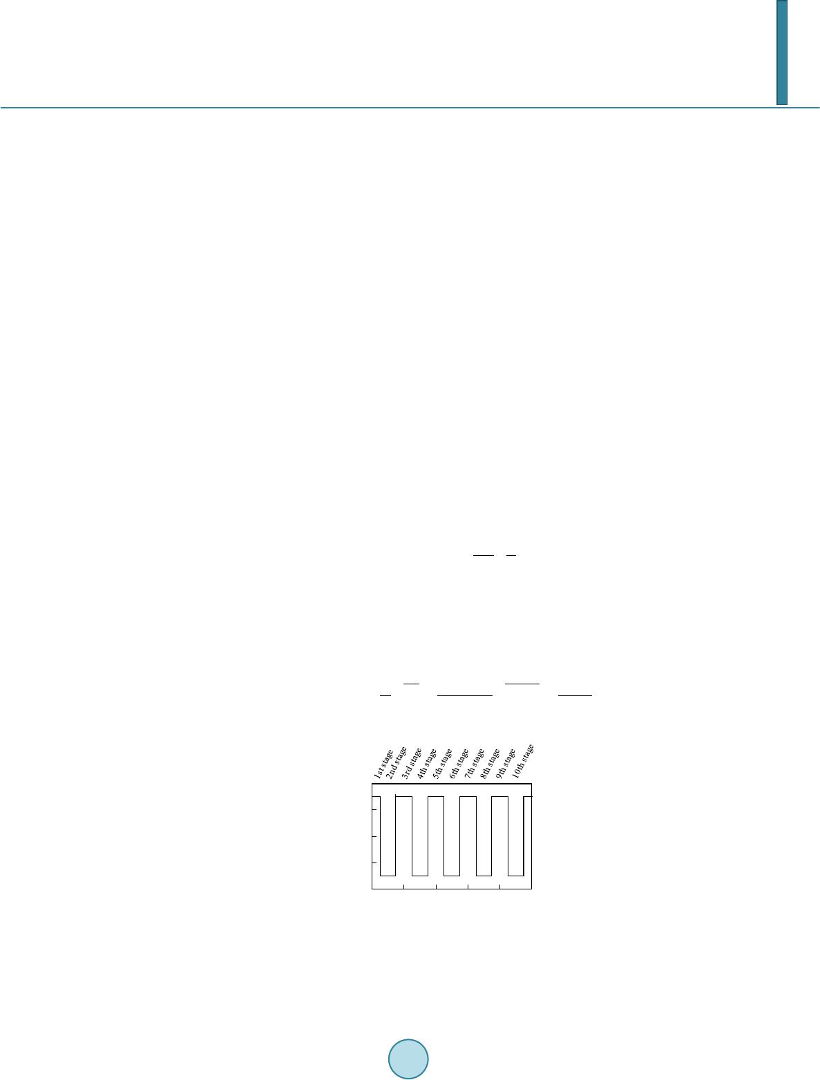 H. Ngetha et al. could associate the charge induced in the Selemion IPMC with the bending curvature of Selemion IPMC quan- titatively. We carried out stability analysis of Selemion IPMC using this circuit model. The circuit equation, re- sulting in the formula of current induced within the Selemion IPMC were analyzed and solved. This gave rise to a formula representing the relationship between the bending curvature and the voltage imposed on the IPMC. Considering the bending curvature and voltage imposed as output and input respectively, a transfer function was derived. Using the derived transfer function, bending stability analysis was performed. This is discussed in the following section of Results and discussion. 4. Results and Discussion The main objective of this paper is the stability analysis of Selemion IPMC bending behavior in the high humid- ity environment. The Selemion IPMC was approximated by a circuit model previously proposed [3], and a transfer function of the Selemion IPMC was derived. Then, stability analysis of Selemion IPMC bending was performed. 4.1. Bending Stability Analysis Bending tests of Selemion IPMC were carried out in various AH environments (AH: absolute humidity) by fol- lowing the procedure described in the section 2.3. Absolute Humidity environments were categorized into three categories; low absolute humidity environment (AH < 6 gm−3), moderate absolute humidity environment (6 gm−3 < AH < 10 gm−3) and high absolute humidity environment (10 gm−3 < AH). In the recent past, Ngetha et al. reported the results of bending stability analysis of Selemion IPMC in low and moderate absolute humidity en- vironments [8]. Thus, in this research work, we only consider the Selemion IPMC in high absolute humidity en- vironment. Figure 1 shows the rectangular voltage pulse train imposed on Selemion IPMC, (1.5 VP, 1/60 Hz). This is al- so represented by Equation (1). ( ) 2πtπ Vt1.5 sgnsin60 2 = + (1) Figure 2 shows the experimental data of time dependence of bending curvature and current of Selemion IPMC at AH = high. Figure 3 shows the circuit model proposed by Ikeda et al. [3]. From the circuit model, Eq- uation (2) representing the current, is derived. All the parameters of Equation (2) were estimated from the current data obtained experimentally [3]. According to the ref. [3], the parameters change in accordance with the pulses, discretely at the moment of stage change, where the definition of stage is given in Figure 1. ( )( )( ) ( ) ss r Rt t r RC rC s 1R 1 It Vtee r rrRrR −+ − =++ ++ (2) Figure 1. Rectangular voltage pulse train 1st stage: 0 s < t < 15 s, 2nd stage: 15 s < 45 s, 3rd stage: 45 s < t <75 s,…, n th stage, (30n – 15) s < t < (30n + 15) s. - 2.00 - 1.00 0.00 1.00 2.00 060120180 240 300 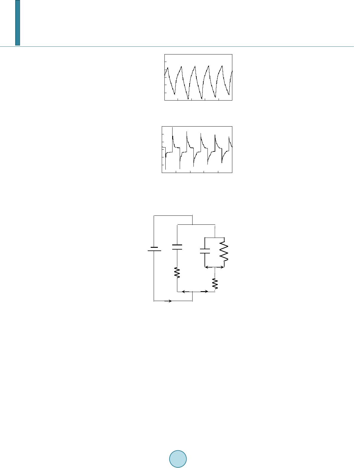 H. Ngetha et al. Figure 2. (a) Curvature vs. time; (b) Current vs. time at AH = 10.1 gm−3. Figure 3. Circuit model representing Sele- mion IPMC under V of the applied voltage. Definitions of notations given in this circuit is given in ref. [3]. Ikeda et al. estimated the values of those parameters (in other words discrete variables) and succeeded in theoretically reproducing the experimental data of current and curvature of Selemion IPMC for 10 stages by employing those estimated parameters [3]. However, we found that experimental data of current is relatively well reproducible even under the assumption that the parameters were constant from the 1st stage through 10th stage. For example, Figure 4 shows the time dependence of experimentally observed current, which is same as Figure 2(a) and the computationally predicted current obtained using Equation (2). The parameters used for the computation were assumed to be constant and summarized in Table 1. The computational prediction of current is in good agreement with the experimental data as clearly seen in Figure 4 even under the assumption that all the parameters are constant. The current, behavior was successfully reproduced as shown in Figure 4, even under the strong as- sumption that the parameters were constant, and it is known that the current (or charge) played a fundamental role of bending induction of Selemion IPMC [3]. Therefore it is speculated that the curvature of IPMC is quan- titatively predictable even under the same strong assumption: the parameters were constant. That assumption - 0.15 - 0.10 - 0.05 0.00 0.05 0.10 0.15 060 120 180 240 300 time / s current / mAmm-2 (b) - 0.009 - 0.006 - 0.003 0.000 0.003 0.006 0.009 060120 180240 300 time / s curvature / mm-1 (a) C ℓ -Q ℓ +Q ℓ R I ℓ I R r ℓ V I r s I r -Q s +Q s C s I s 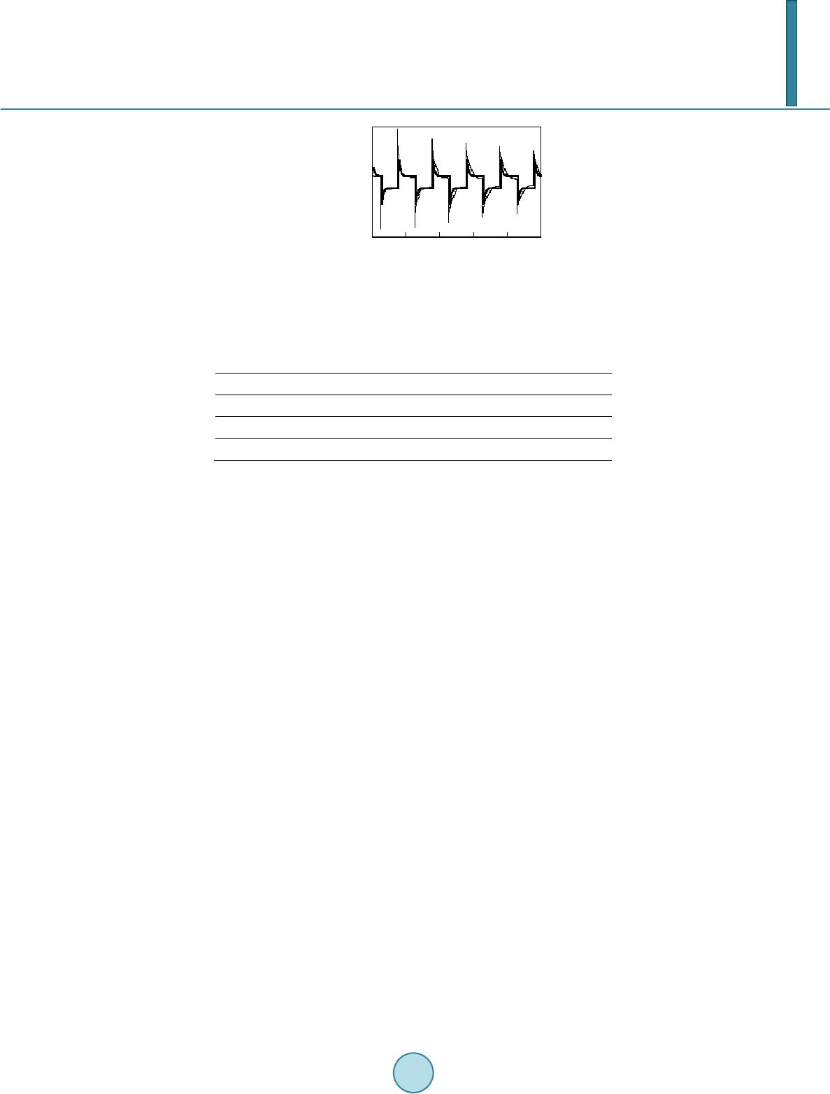 H. Ngetha et al. Figure 4. Current vs. time at AH = 10.1 gm−3 Fine line: experimental Thick line: computa- tional. Table 1. Parameters of Equation (2). τs/s τℓ/s Cs/mFmm−2 Cℓ/mFmm−2 0.80 2.70 0.0385 0.1182 rs/kΩmm2 rℓ/kΩmm2 R/kΩmm2 20.797 3 8. 826 55.513 makes the bending stability analysis for Selemion IPMC quite easy and simple. Therefore, the same assumption is used for the bending stability analysis, explained in the following section. 4.2. Bending Stability Analysis We previously performed stability analysis of Selemion IPMC bending at AH = low and moderate [8]. Since the curvature of Selemion IPMC was virtually proportional to the total charge it imposed on it at AH = low and moderate (in other words, AH < 10 gm−3), we carried out bending analysis in case AH < 10 gm−3 by assuming that [curvature of Selemion IPMC] ∝ [total charge imposed on the Selemion IPMC]. Hence, it was quite easy to computationally predict the curvature expected, since [total charge imposed on the Selemion IPMC] could be obtained simply by taking time integration of Equation (2), and we derived a conclusion that the bending beha- vior of Selemion was marginally stable. But the same analysis is inapplicable for the stability analysis of Sele- mion IPMC bending at AH = high, since [curvature of Selemion IPMC] ∝ [total charge imposed on the Sele- mion IPMC] cannot hold at AH = high. There are two kinds of charges; one displays no influence on the bend- ing induction and another one displays the significant influence on the bending induction as described earlier in this paper. The quantity of former charge is not negligibly small at AH = high. So, it was fundamental to indivi- dually evaluate the influence of both charges on the bending induction and eliminate the former charge for the bending stability analysis of Selemion IPMC. For carrying out the evaluation of those charges individually, it was necessary to estimate all the parameters in Equation (2) at AH = high. For the precise analysis of bending stability, it was necessary to assume that those parameters were not constant but discretely changeable. However, we employed the assumption that the parameters were not discretely variable but constant for simplifying the bending stability analysis procedure. Though it was a bold assumption, such a bold assumption provided the computational data of current which well reproduced the experimental data of current as shown in Figure 4. Ikeda et al. suggested that the total quantity of charge flowing through represented by and another charge stored in represented by played fundamental role of bending induction and the rest of the charge did not influence on the bending induction at all. The bending curvature (B) expected is represented by Equation (3), where and were constant and were estimated experimentally. (3) The analytical expression of and can be obtained by solving circuit equation. For example; and at the 1st stage are respectively given by Equations (4) and (5). Hence, it was possible to estimate B using Equation (2) [3]. The analytical expression of and at the further stages can be obtained as well. -0.15 -0.10 -0.05 0.00 0.05 0.10 0.15 060120180 240 300 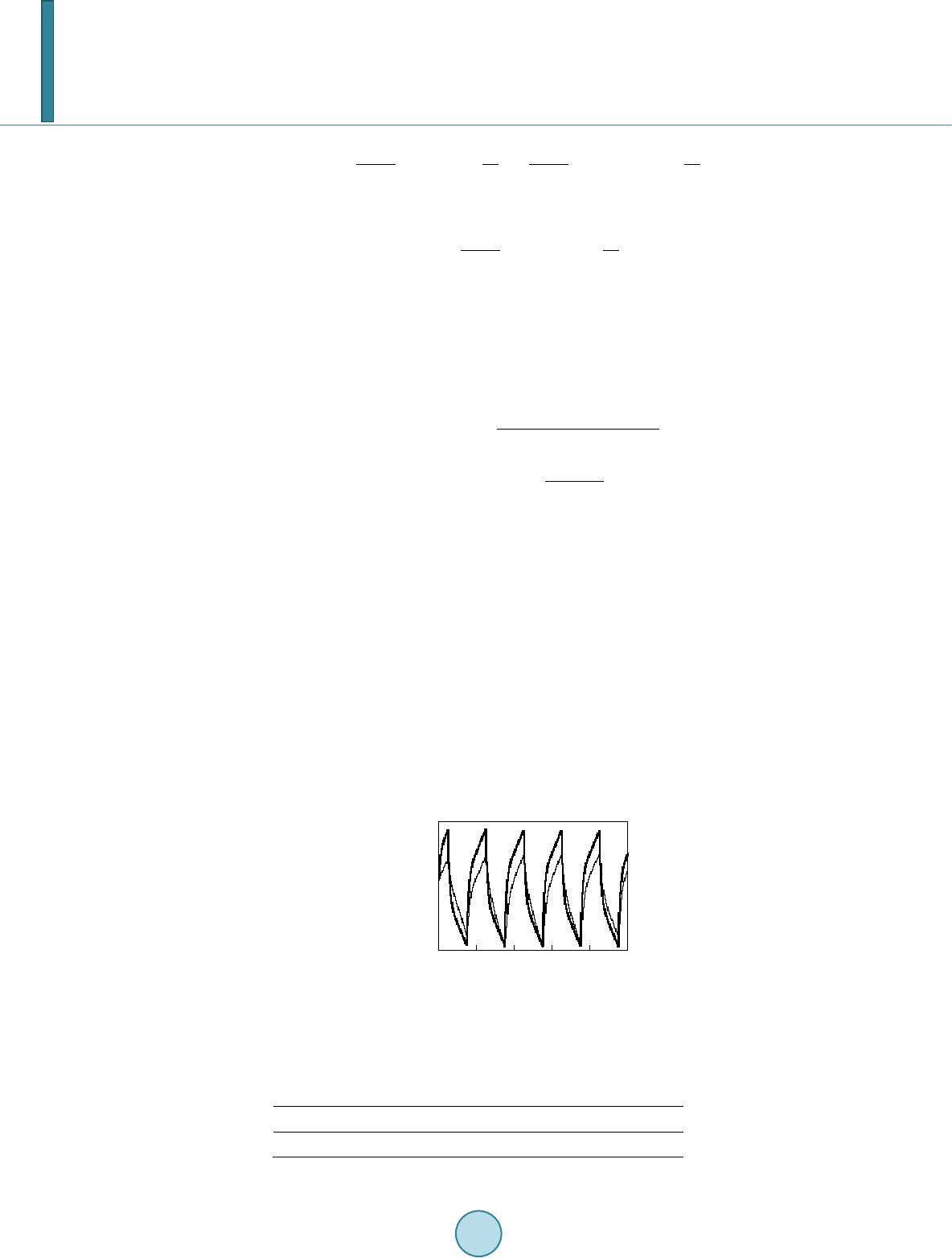 H. Ngetha et al. r RC tV t QV 1exptτ1 exp rR τrR τ =−−+ −−− ++ (4) Rt QC V1exp rR τ = −− + (5) For the stability analysis of Selemion IPMC at AH = 10 gm−3, we employed Equations (3), (4) and (5) and the parameters shown in Table 1, and we also employed the coefficients of kF = 0.0145 m·C−1 and knF = 0.0112 m·C−1. By the use of the parameters given in Table 1 and the Equations (2), (3), (4) and (5), the transfer func- tions, given by Equations (6) and (7) were derived. The transfer function, given by Equation (7) suffices the relationship given by Equation (8). As clearly understood, Equation (6) associates the transfer function with the bending curvature of Selemion IPMC and Equation (7) associated another transfer function with current. ()( ) 2 20.4011s 1 BsVs 19527.436s7225.151s + = + (6) ( )( ) s 0.03 IsVs s 0.149 + = + (7) (8) Primary purpose of this study lie in the bending stability analysis of Selemion IPMC, and the transfer func- tions in Equations (6) and (7) are employed for the analysis. But prior to carrying out the bending stability anal- ysis, we carried out the computational prediction of bending curvature using Equation (6). Figure 5 shows the time dependence of experimentally observed curvature, which is same as Figure 2(b) and the computationally predicted curvature. Both experimental and computational curvatures are in good agreement each other. Hence, the theoretical treatment so far we have introduced is trustworthy enough. An open loop system model was built using the MATLAB. Using the open loop transfer functions—the po- lynomial expressions given in Equations (6) and (7)—the following results were obtained: Figure 6 shows the root locus diagram, and poles and zeros are summarized in Table 2. For a zero steady-state error, lims→0 I(s) = ∞ and for limit to be finite, at least one pole must be at the origin s = 0. The results suggest that the system is marginally stable. Since we assumed that the Selemion IPMC curvature is not directly proportional to the charge imposed on the Selemion IPMC, and the charge is not given merely by the time integration of current. Hence, the Selemion IPMC bending behavior is also marginally stable. Figure 5. Curvature vs. time at AH = 10.1 gm−3 Fine line: experimental Thick line: com- putational. Table 2. Pole and Zero of the open loop system model. High humidity Pole Zero −0.149 −0.03 -0.009 -0.006 -0.003 0.000 0.003 0.006 0.009 060120 180 240300  H. Ngetha et al. Figure 7 shows the experimental and computational response of current to the input of Heaviside step func- tion voltage. The experimental result shown in Figure 7 indicate s the existence of a large time delay and that the system was highly dumped under the high humidity conditions. The computational results do not well reproduce the experimental results. However, qualitative characteristics—a large time delay and highly dumped system— were relatively well reproduced. For high humidity condition, the pole is located close to the origin (see Table 2). This makes the whole sys- tem behave like an integrator, which is clearly shown by Figure 8 of Bode plot. We carried out further analysis of system stability. Figure 9 is a Nyquist plot and it indicates that the system is basically marginally stable at any frequency. Figure 6 . The root locus diagram. Figure 7. The response to a voltage represented by V(t) =1.5∙H(t), where H(t) is Heaviside step function. Fine line: experimental Thick line: computational. Figure 8. The bode plot. 0.00 0.01 0.02 0.03 0.04 060120 180240 300  H. Ngetha et al. Figure 9 . Nyquist root plot. 5. Conclusions Based on the circuit model, the transfer function was derived. Those transfer functions successfully reproduced the experimentally obtained bending and current behaviors of Selemion IPMC. Hence, the transfer functions de- rived is quite reliable. Analyzing the transfer functions we obtained and validated, it was found that the Sele- mion IPMC has the following characteristics. 1) There exists a large time delay in the current in response to the voltage input. 2) Current is highly dumping. 3) Bending behavior is marginally stable under the input at any frequency. Acknowledgements The authors would like to express their gratitude to the Ministry of Education, Culture, Sports, Science and Technology for financial support under the Grant-in-Aid for Scientific Research (C), 24560291. References [1] Tamag awa, H. and Nogata, F. (2004) Bending Response of Dehydrated Ion Exchange Polymer Membrane to the Ap- plied Voltage. Journal of Membrane Science, 243 , 229 -234. http://dx.doi.org/10.1016/j.memsci.2004.06 .02 4 [2] Onouchi, Y., Sasaki, M. and Tamagawa, H. (2009) Current-Controlled Selemion Bending in the Controlled Humidity Environment. Sensors and Actuators B: Chemical, 135, 465-471. http://dx.doi.org/10.1016/j.snb.2008.10.025 [3] Ikeda, K., Sasaki, M. and Tamagawa, H. (2014) IPMC Bending Predicted by the Circuit and Viscoelastic Models Con- sidering Individual Influence of Faradaic and Non-Faradaic Currents on the Bending. Sensors and Actuators B: Chem- ical, 190, 954-967 . http://dx.doi.org/10.1016/j.snb.2013.09.016 [4] Porfiri, M. (2008) Charge Dynamics in Ionic Polymer Metal Composites. Journal of Applied Physics, 104 , Article ID: 104915. http://dx.doi.org/10.1063/1.3017467 [5] Bran co, P.J.C. an d Dent e, J.A. (2006) Derivation of a Continuum Model and Its Electric Equivalent-Circuit Represen- tation for Ionic Polymer-Metal Composite (IPMC). Elect romech anics, Smart Materials and Structures, 15, 378. http://dx.doi.org/10.1088/0964-1726/15/2/019 [6] Farinholt, K. and Donald, J.L. (2004) Modeling of Electromechanical Charge Sensing in Ionic Polymer Transducers. Mechanics of Materials, 36, 421-433. http://dx.doi.org/10.1016/S0167-6636(03 )00 069 -3 [7] Ikeda, K., Sasaki, M. and Tamagawa, H. Rotational Trajectory Formation of Curvature vs. Charge Relationship by Se- lemion CMV-Based IPMC. To be submitted. [8] Nget ha, H., Sasaki, M., Tamagawa, H., Ikeda, K. and Ito, S. (2013) A Stabilized Control Lability of Selemion CMV-Based IPMC Actuators in the Extremely Low Humidity Environment. Proceedings of the 22nd Annual Interna- tional Conference of MAGDA, Miyazaki, Japan, 2-3 December 2013, 555-560. -0.01 0.000.01 0.020.03 real axis -5 0 5 imaginary axis
|