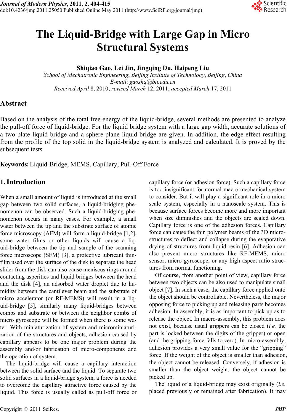
 Journal of Modern Physics, 2011, 2, 404-415 doi:10.4236/jmp.2011.25050 Published Online May 2011 (http://www.SciRP.org/journal/jmp) Copyright © 2011 SciRes. JMP The Liquid-Bridge with Large Gap in Micro Structural Systems Shiqiao Gao, Lei Jin, Jingqing Du, Haipeng Liu School of Mechatronic Engineering, Beijing Institute of Technology, Beijing, China E-mail: gaoshq@bit.edu.cn Received April 8, 2010; revised March 12, 2011; accepted March 17, 2011 Abstract Based on the analysis of the total free energy of the liquid-bridge, several methods are presented to analyze the pull-off force of liquid-bridge. For the liquid bridge system with a large gap width, accurate solutions of a two-plate liquid bridge and a sphere-plane liquid bridge are given. In addition, the edge-effect resulting from the profile of the top solid in the liquid-bridge system is analyzed and calculated. It is proved by the subsequent tests. Keywords: Liquid-Bridge, MEMS, Capillary, Pull-Off Force 1. Introduction When a small amount of liquid is introduced at the small gap between two solid surfaces, a liquid-bridging phe- nomenon can be observed. Such a liquid-bridging phe- nomenon occurs in many cases. For example, a small water between the tip and the substrate surface of atomic force microscopy (AFM) will form a liquid-bridge [1,2], some water films or other liquids will cause a liq- uid-bridge between the tip and sample of the scanning force microscope (SFM) [3], a protective lubricant thin- film used over the surface of the disk to separate the head slider from the disk can also cause meniscus rings around contacting asperities and liquid bridg es between the head and the disk [4], an adsorbed water droplet due to hu- midity between the cantilever beam and the substrate of micro accelerator (or RF-MEMS) will result in a liq- uid-bridge [5], similarly many liquid-bridges between combs and substrate or between the neighbor combs of micro gyroscope will be formed when there is some wa- ter. With miniaturization of system and microminiaturi- zation of the structures and objects, adhesion caused by capillary appears to be one major problem during the assembly and/or fabrication of micro-components and the operation of system. The liquid-bridge will cause a capillary interaction between the solid surface and th e liquid. To separate two solid surfaces in a liquid-bridge system, a force is needed to overcome the capillary attractive force caused by the liquid. This force is usually called as pull-off force or capillary force (or adhesion force). Such a cap illary force is too insignificant for normal macro mechanical system to consider. But it will play a significant role in a micro scale system, especially in a nanoscale system. This is because surface forces become more and more important when size diminishes and the objects are scaled down. Capillary force is one of the adhesion forces. Capillary force can cause the thin polymer beams of the 3D micro- structures to deflect and collapse during the evaporative drying of structures from liquid resin [6]. Adhesion can also prevent micro structures like RF-MEMS, micro sensor, micro gyroscope, or any high aspect ratio struc- tures from normal functioning. Of course, from another point of view, capillary force between two objects can be also used to manipulate small object [7]. In such a case, the capillary force applied on to the object should be controllable. Nevertheless, the major opposing forc e to picking up and releasing parts becomes adhesion. In assembly, it is as important to pick up as to release the object. In macro-assembly, this problem does not exist, because usual grippers can be closed (i.e. the part is locked between the digits of the gripper) or open (and the gripping force falls to zero). In micro-assembly, adhesion provides a very small value for the “gripping” force. If the weight of the object is smaller than adhesion, the object cannot be released. Conversely, if adhesion is smaller than the object weight, the object cannot be picked up. The liquid of a liquid-bridge may exist originally (i.e. placed previously or remained after fabrication). It may 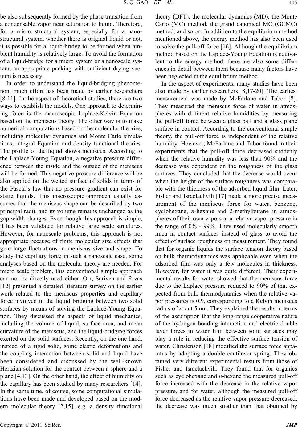 S. Q. GAO ET AL.405 be also subsequently formed by the phase transition from a condensable vapor near saturation to liquid. Therefore, for a micro structural system, especially for a nano- structural system, whether there is original liquid or not, it is possible for a liquid-bridge to be formed when am- bient humidity is relatively large. To avoid the formation of a liquid-bridge for a micro system or a nanoscale sys- tem, an appropriate packing with sufficient drying vac- uum is necessary. In order to understand the liquid-bridging phenome- non, much effort has been made by earlier researchers [8-11]. In the aspect of theoretical studies, there are two ways to establish the models. One app roach to determin- ing force is the macroscopic Laplace-Kelvin Equation based on the meniscus theory. The other way is to make numerical computations based on the molecular theories, including molecular dynamics and Monte Carlo simula- tions, integral Equation and density functional theories. The profile of the liquid shows meniscus. According to the Laplace-Young Equation, a negative pressure differ- ence between the inside and the outside of the meniscus will be formed. This negative pressure difference will be also applied on the wetted surface of solids in terms of the Pascal’s law that no pressure gradient can exist for static liquids. This macroscopic approach usually as- sumes that the meniscus shape can be described by two principal radii, and its volume remains unchanged as the gap width chan ges. Even though this approach is simple, it has been validated for relative large scale structures. However, for nanoscale problems, this approach is not appropriate because of finite molecular size effects that give large fluctuations in meniscus size and shape. To study the capillary force in such a nanoscale case, some analyses based on the molecular theory are needed. For micro scale problem, this conventional simple approach can not be directly used either. Orr, Scriven and Rivas [12] presented a detailed literature survey on the earlier work related to the meniscus properties and capillary force involved in the liquid bridging between two solid surfaces by means of solving the Laplace-Young Equa- tion. They discussed the aspects of liquid mechanics, including the volume of liquid, surface area, and mean curvature of the meniscus, and the liquid-bridging forces exerted on the solid surfaces. Recently, on the one hand, instead of a rigid solid, some elastic deformations and the coupling interaction between solid and liquid have been considered and discussed by the well-known Hertzian solution for the contact between a sphere and a plane [4,13]. On the other hand, the effect of humidity on the capillary has been studied by many researchers [14]. In the same time, of course, some computational simula- tions have been made and developed based on the mod- ern molecular theory [2,15], e.g. a density functional theory (DFT), the molecular dynamics (MD), the Monte Carlo (MC) method, the grand canonical MC (GCMC) method, and so on. In addition to the equilibrium method mentioned above, the energy method has also been used to solve the pull-off force [16]. Although the equilibrium method based on the Laplace-Young Equation is equiva- lent to the energy method, there are also some differ- ences in detail between them because many factors have been neglected in the equilibrium method. In the aspect of experiments, many studies have been also made by earlier researchers [8,17-20]. The earliest measurement was made by McFarlane and Tabor [8]. They measured the meniscus force of water in atmos- pheres with different relative humidities by measuring the pull-off force between a glass ball and a glass plane surface in contact. According to the conventional simple theory, the pull-off force is independent of the relative humidity. However, McFarlane and Tabor found in their experiments that the pull-off force decreased suddenly when the relative humidity was less than 90% and the decrease was dependent on the roughness of the glass surfaces. They concluded that the decrease would occur when the height of the surface roughness was compara- ble with the thickness of the adsorbed liquid film. Later, Fisher and Israelachvili [17] made a more precise meas- urement of the meniscus force for water, benzene, cyclohexane, n-hexane and 2-methylbutane in atmos- pheres of their own vapors at a relative vapor pressure in the range of 0% - 99%. They used molecularly smooth mica in contact surfaces instead of glass to avoid the effect of surface roughness on measurement. They found that for organic liquids the surface tension theory based on bulk thermodynamics was applicable even when the adsorbed film was only a few molecules in thickness. However, for water it was quite different. Their experi- mental results for water showed that the meniscus force due to the Laplace pressure reduced to 90% of that ex- pected from bulk thermodynamics when the relative va- por pressures is 0.9, corresponding to a Kelvin meniscus radius of about 5 nm. They explained the results in terms of the assumption that the long-range cooperative nature of the hydrogen bonding interaction and electric double layer forces in water film between solid surfaces may play a role in reducing the effective surface tension of water. Christenson [18] modified the surface force appa- ratus by adopting a double cantilever spring. They ob- tained very different experimental results from those of Fisher and Israelachvili. They found that for organics such as cyclohexane and n-hexane the measured pull-off force increased with the decrease in the relative vapor pressure, and for water, although the measured pull-off force decreased as the relative vapor pressure decreased, the decrease was much smaller than that obtained by Copyright © 2011 SciRes. JMP 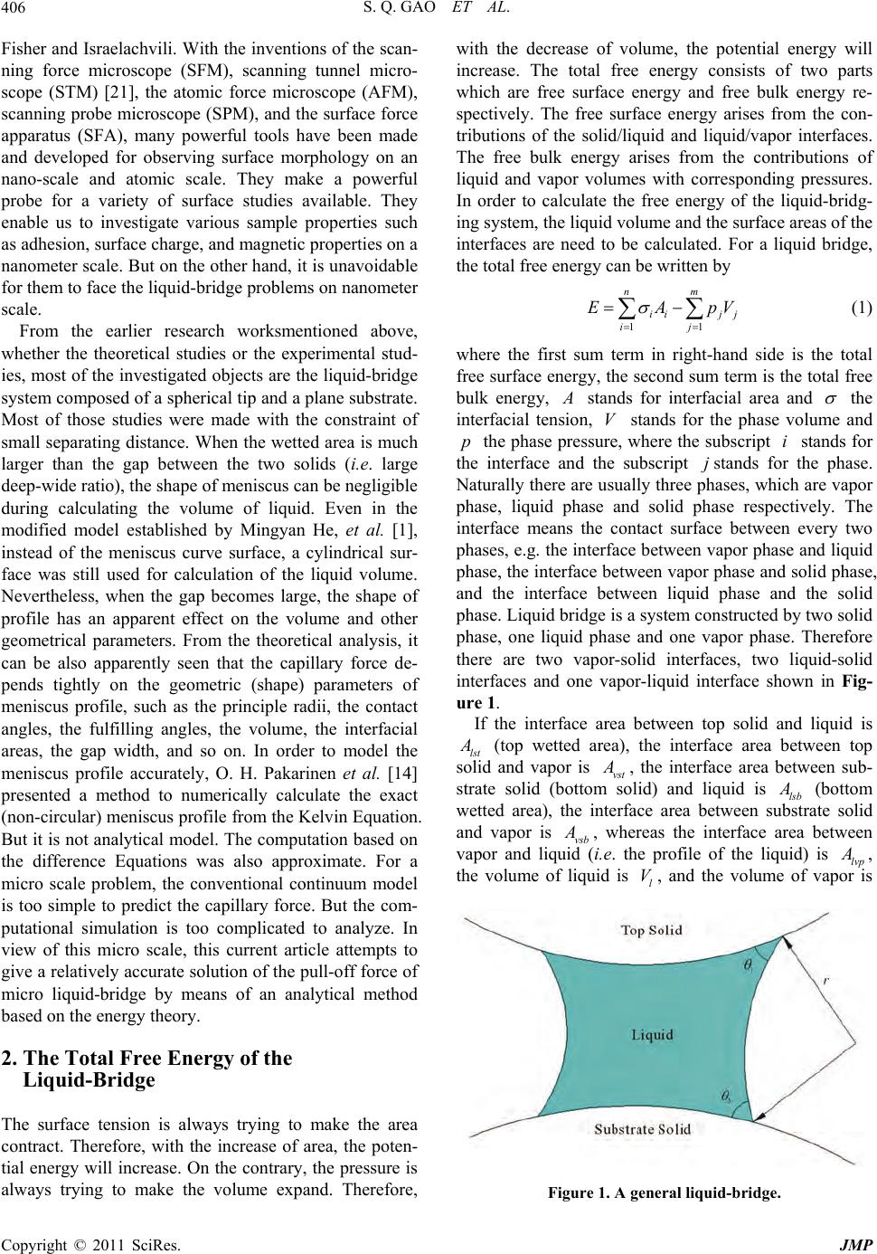 S. Q. GAO ET AL. 406 V Fisher and Israelachvili. With th e inventions of the scan- ning force microscope (SFM), scanning tunnel micro- scope (STM) [21], the atomic force microscope (AFM), scanning probe microscope (SPM), and the surface force apparatus (SFA), many powerful tools have been made and developed for observing surface morphology on an nano-scale and atomic scale. They make a powerful probe for a variety of surface studies available. They enable us to investigate various sample properties such as adhesion, surface charge, and magnetic properties on a nanometer scale. But on the other hand , it is unavoidable for them to face the liquid-bridge problems on nanometer scale. From the earlier research worksmentioned above, whether the theoretical studies or the experimental stud- ies, most of the investigated objects are the liquid-bridge system composed of a spherical tip and a plane substrate. Most of those studies were made with the constraint of small separating distance. When the wetted area is much larger than the gap between the two solids (i.e. large deep-wide ratio), the shape of meniscus can be negligible during calculating the volume of liquid. Even in the modified model established by Mingyan He, et al. [1], instead of the meniscus curve surface, a cylindrical sur- face was still used for calculation of the liquid volume. Nevertheless, when the gap becomes large, the shape of profile has an apparent effect on the volume and other geometrical parameters. From the theoretical analysis, it can be also apparently seen that the capillary force de- pends tightly on the geometric (shape) parameters of meniscus profile, such as the principle radii, the contact angles, the fulfilling angles, the volume, the interfacial areas, the gap width, and so on. In order to model the meniscus profile accurately, O. H. Pakarinen et al. [14] presented a method to numerically calculate the exact (non-circu lar) men iscus pr ofile fro m the Kelvin Equation. But it is not analytical model. The co mputation based on the difference Equations was also approximate. For a micro scale problem, the conventional continuum model is too simple to predict the capillary force. But the com- putational simulation is too complicated to analyze. In view of this micro scale, this current article attempts to give a relatively accurate solution of the pull-off force of micro liquid-bridge by means of an analytical method based on the energy theory. 2. The Total Free Energy of the Liquid-Bridge The surface tension is always trying to make the area contract. Therefore, with the increase of area, the poten- tial energy will increase. On the contrary, the pressure is always trying to make the volume expand. Therefore, with the decrease of volume, the potential energy will increase. The total free energy consists of two parts which are free surface energy and free bulk energy re- spectively. The free surface energy arises from the con- tributions of the solid/liquid and liquid/vapor interfaces. The free bulk energy arises from the contributions of liquid and vapor volumes with corresponding pressures. In order to calculate the free energy of the liquid-bridg- ing system, the liquid volume and the surface areas of the interfaces are need to be calculated. For a liquid bridge, the total free energy can be written by 11 nm ii jj ij EAp (1) where the first sum term in right-hand side is the total free su rface energy, th e second sum te rm is the total fr ee bulk energy, stands for interfacial area and the interfacial tension, stands for the phase volume and the phase pressure, where the subscript stands for the interface and the subscript stands for the phase. Naturally there are usually three phases, which are vapor phase, liquid phase and solid phase respectively. The interface means the contact surface between every two phases, e.g. the interface between vapor phase and liquid phase, the interface between vapor phase and solid phase, and the interface between liquid phase and the solid phase. Liquid bridge is a system constructed by two solid phase, one liquid phase and one vapor phase. Therefore there are two vapor-solid interfaces, two liquid-solid interfaces and one vapor-liquid interface shown in Fig- ure 1. V p i j If the interface area between top solid and liquid is lst (top wetted area), the interface area between top solid and vapor is vst , the interface area between sub- strate solid (bottom solid) and liquid is lsb (bottom wetted area), the interface area between substrate solid and vapor is vsb , whereas the interface area between vapor and liquid (i.e. the profile of the liquid) is lvp , the volume of liquid is , and the volume of vapor is l V Figure 1. A general liquid-bridge. Copyright © 2011 SciRes. JMP 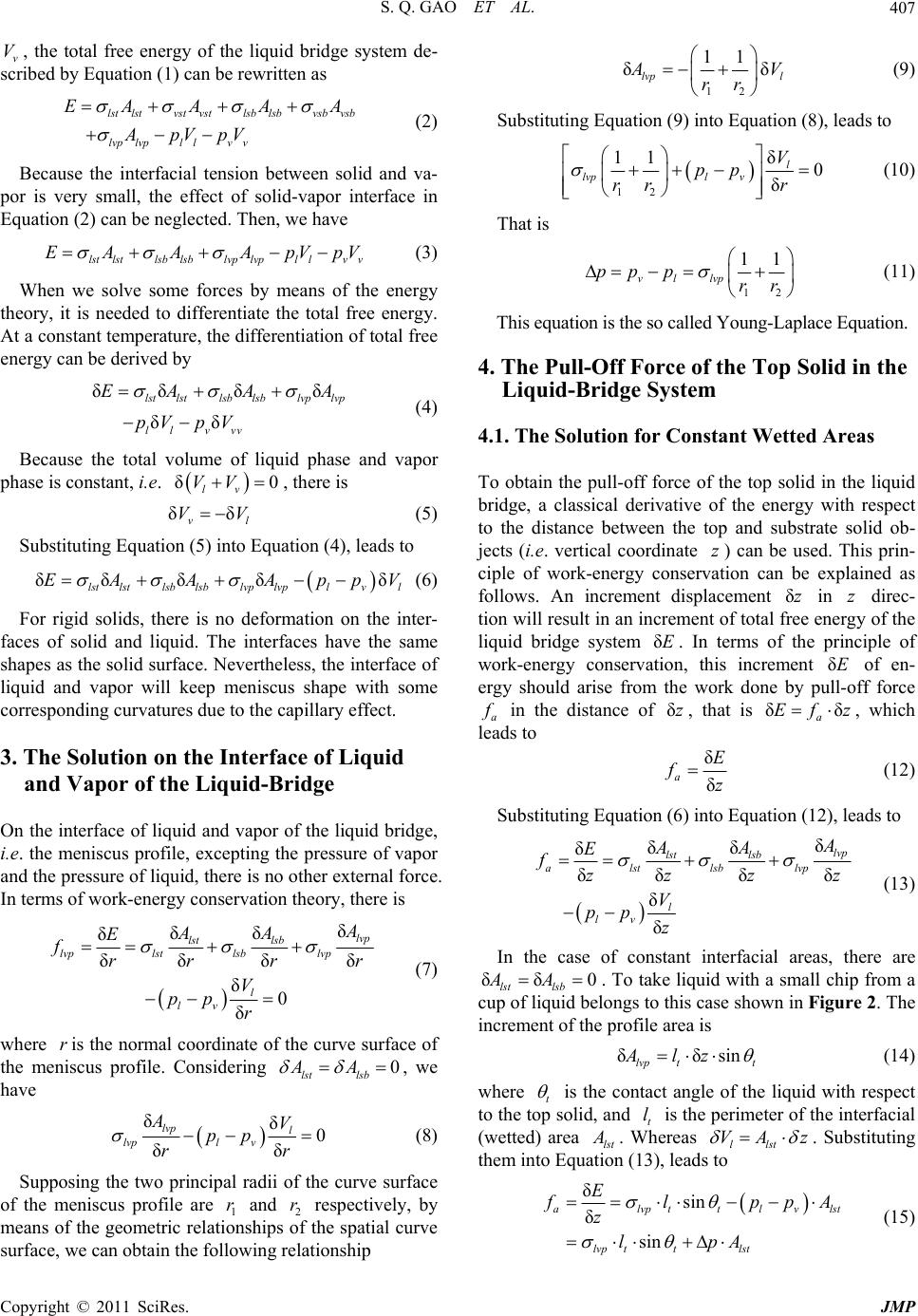 S. Q. GAO ET AL.407 v, the total free energy of the liquid bridge system de- scribed by Equation (1) can be rewritten as V lstlstvstvstlsb lsbvsb vsb lvplvpl lvv EA AAA ApVpV (2) Because the interfacial tension between solid and va- por is very small, the effect of solid-vapor interface in Equation (2) can be neglected. Then, we have lstlstlsblsblvplvpl lvv EA AApVpV (3) When we solve some forces by means of the energy theory, it is needed to differentiate the total free energy. At a constant temperature, the differentiation of total free energy can be derived by δδ δδ δδ lstlstlsb lsblvp lvp ll vvv EA AA pV pV (4) Because the total volume of liquid phase and vapor phase is constant, i.e. , there is δ0 lv VV δδ v V l V V (5) Substituting Equation (5) into Equation (4), leads to δδ δδδ lstlstlsb lsblvp lvplvl EA AApp (6) For rigid solids, there is no deformation on the inter- faces of solid and liquid. The interfaces have the same shapes as the solid surface. Nevertheless, the in terface of liquid and vapor will keep meniscus shape with some corresponding curvatures due to the capillary effect. 3. The Solution on the Interface of Liquid and Vapor of the Liquid-Bridge On the interface of liquid and vapor of the liquid bridge, i.e. the meniscus profile, excepting the pressure of vapor and the pressure of liquid, there is no other external force. In terms of work-energy conservation theory, there is δ δδ δ δδ δ δ 0 δ lvp lst lsb lvplst lsblvp l lv δ AA E frr r V pp r r (7) where is the normal coordinate of the curve surface of the meniscus profile. Considering r0 lst lsb AA , we have δδ0 δδ lvp l lvpl v AV pp rr (8) Supposing the two principal radii of the curve surface of the meniscus profile are 1 and 2 respectively, by means of the geometric relationships of the spatial curve surface, we can obtain the following relationship r r 12 11 δ lvp l δ V rr (9) Substituting Equation (9) into Equation (8), leads to 12 δ 11 0 δ l lvpl v V pp rr r (10) That is 12 11 vl lvp pp prr (11) This equation is the so called Young-Lapl ace Equation. 4. The Pull-Off Force of the Top Solid in the Liquid-Bridge System 4.1. The Solution for Constant Wetted Areas To obtain the pull-off force of the top solid in the liquid bridge, a classical derivative of the energy with respect to the distance between the top and substrate solid ob- jects (i.e. vertical coordinate ) can be used. This prin- ciple of work-energy conservation can be explained as follows. An increment displacement in direc- tion will result in an in crement of total free energy of the liquid bridge system . In terms of the principle of work-energy conservation, this increment of en- ergy should arise from the work done by pull-off force a z δz z E δE δ in the distance of , that is , which leads to δzδEfδ az δ δ aE fz (12) Substituting Equation (6) into Equation (12), leads to δ δδ δ δδ δ δ δ lvp lst lsb alstlsblvp l lv δ AA E fzz z V pp z z (13) In the case of constant interfacial areas, there are δδ 0 lst lsb AA . To take liquid with a small chip from a cup of liquid belongs to this case shown in Figure 2. The increment of the profile area is δδsin lvp tt Alz (14) where t is the contact angle of the liquid with respect to the top solid, and t is the perimeter of the interfacial (wetted) area lst l . Whereas llst VA z . Substituting them into Equation (13), leads to δsin δ sin alvpttlv lvp ttlst Elst lpp zlpA A (15) Copyright © 2011 SciRes. JMP 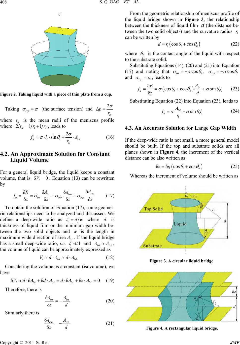 S. Q. GAO ET AL. 408 Figure 2. Taking liquid with a piece of thin plate from a cup. Taking lvp (the surface tension) and 2 m pr where is the mean radii of the meniscus profile where m r 1 211 m rr 2 r, leads to 2 sin att mlst l rA (16) 4.2. An Approximate Solution for Constant Liquid Volume For a general liquid bridge, the liquid keeps a constant volume, that is . Equation (13) can be rewritten by δ0 l V δ δδ δ δδ δ lvp lst lsb alstlsblvp δ AA E fzz z z (17) To obtain the solution of Eq uation (17), some geomet- ric relationships need to be analyzed and discussed. We define a deep-wide ratio as dw where is thickness of liquid film or the minimum gap width be- tween the two solid objects and is the length in maximum wide direction of area d w tls . If the liquid bridge has a small deep-wide ratio, i.e. 1 and lst lsb A , the volume of liquid can be approximately expressed as llst VdA dA lsb (18) Considering the volume as a constant (isovolume), we have δδδδδ0 llstlstlstlst VdAdA dAzA (19) Therefore, there is δ δ lst lst A zd (20) Similarly there is δ δ lsb lsb A zd (21) From the geometric relationship of meniscus profile of the liquid bridge shown in Figure 3, the relationship between the thickness of liquid film (the distance be- tween the two solid objects) and the curvature radius can be written by d 1 r 1cos cos t dr b (22) where b is the contact angle of the liquid with respect to the substrate solid. Substituting Equ ations (1 4), (20 ) and (2 1) into Eq uation (17) and noting that cos lst t , cos lsb b and lvp , leads to δcos cossin δ lst atb A Ett l zd (23) Substituting Equation (22) into Equation (23), lead s to 1 sin lst att l r (24) 4.3. An Accurate Solution for Large Gap Width If the deep-wide ratio is not small, a more general model should be built. If the top and substrate solids are all planes shown in Figure 4, the increment of the vertical distance can be also written as 1 δδcos cos t zr b (25) Whereas the increment of volume should be written as Figure 3. A circular liquid bridge. Figure 4. A rectangular liquid bridge. Copyright © 2011 SciRes. JMP 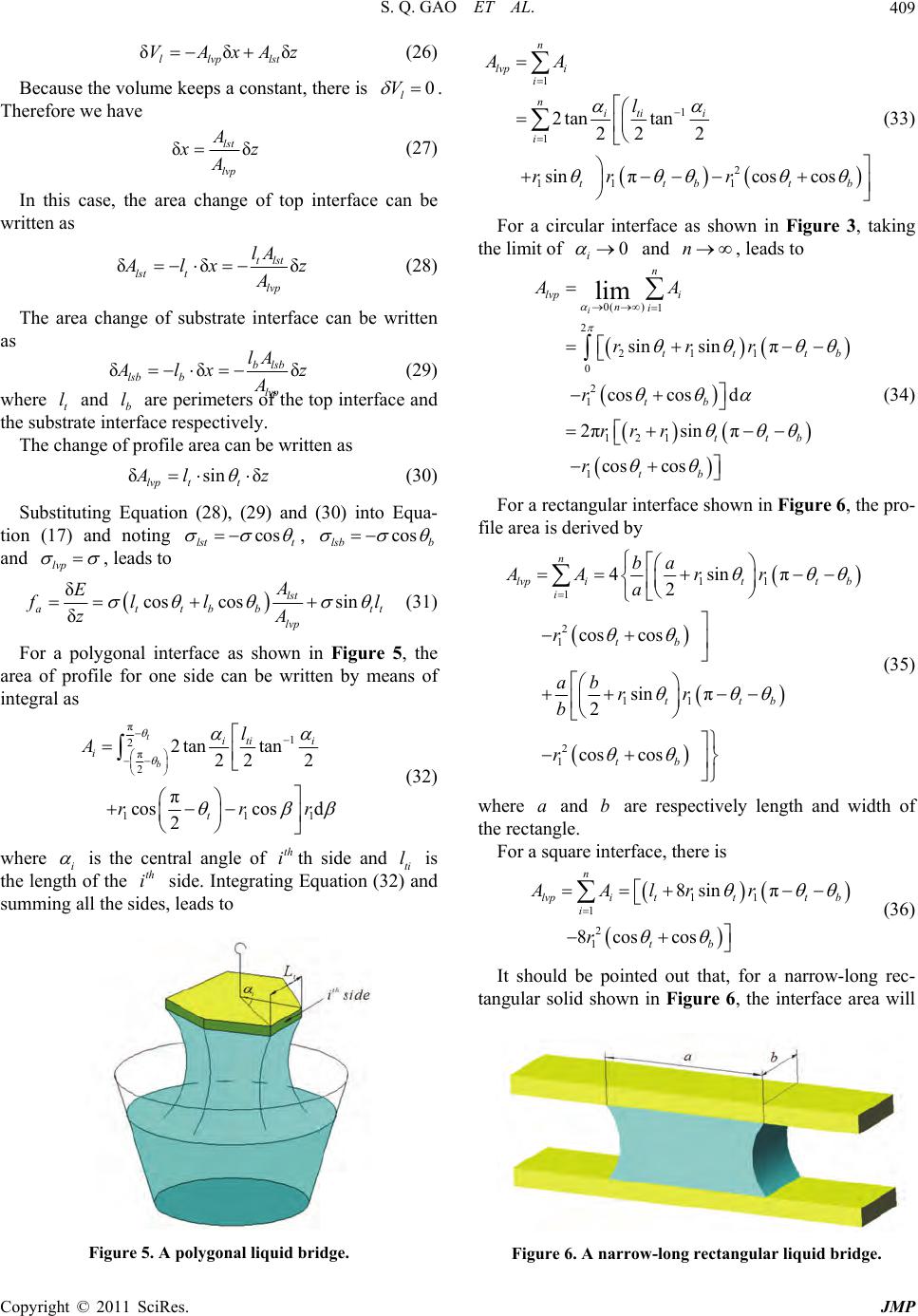 S. Q. GAO ET AL.409 δzδδ l lvplst VAxA (26) Because the volume keeps a constant, there is 0 l V . Therefore we have δ lst lvp δ z A (27) In this case, the area change of top interface can be written as δδ tlst lst tlvp lA δ lx z A (28) The area change of substrate interface can be written as δδ blsb lsb bδ lA lvp lx z A where t and b are perimeters of the top interface and the substrate interface respectively. (29) l l The change of profile area can be written as δsinδ lvp tt lz (30) Substituting Equation (28), (29) and (30) into Equa- tion (17) and noting cos lst t , cos lsb b and lvp , leads to δcos cossin δ lst attbb lvp A E fll zA tt l (31) For a polygonal interface as shown in Figure 5, the area of profile for one side can be written by means of integral as π 1 2 π 2 11 2tan tan 22 2 π coscos d 2 t b iti i i t l A rr 1 r (32) where i is the central angle of th side and ti is the length of the side. Integrating Equation (32) and summing all the sides, lead s to th i l th i 1 1 1 2 11 1 2tan tan 22 2 sin πcos cos n lvp i i nitii i ttb t AA l rr r b (33) For a circular interface as shown in Figure 3, taking the limit of 0 i and n, leads to n AA 0() 1 2 211 0 2 1 121 1 sin sinπ cos cosd 2πsin π cos cos lim i lvp i ni tt t tb ttb tb rrr r rrr r b (34) For a rectangular interface shown in Figure 6, the pro- file area is derived by 11 1 2 1 11 2 1 4sinπ 2 cos cos sin π 2 cos cos nb AA lvp itt b i tb ttb tb a rr a r ab rr b r (35) where and are respectively length and width of an ab the rectgle. For a square interface, there is 8sin n lvpi t AAlr 11 1 2 1 π 8coscos tt b i tb r r (36) It should be pointed out that, for a narrow-long rec- tangular solid shown in Figure 6, the interface area will Figure 5. A polygonal liquid bridge. Figure 6. A narrow-long rectangular liquid bridge. Copyright © 2011 SciRes. JMP 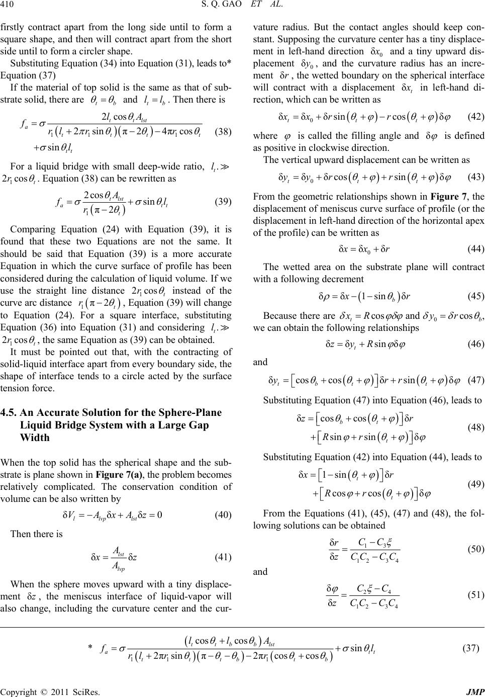 S. Q. GAO ET AL. Copyright © 2011 SciRes. JMP 410 first a qua t i on ( 31), l ead s to * Eq al of top solid is the same as that of sub- st vature radius. But the contact angles should keep con- stant. Supposing the curvature center has a tiny displace- ment in left-hand direction 0 δ and a tiny upward dis- placement 0, and the curvature radius has an incre- ment , the wetted boundary on the spherical interface will contract with a displacement δy δr δt in left-hand di- rection, which can be written as ly contract apart from the long side until to form square shape, and then will contract apart from the short side until to form a circler shape. Substituting Equation (34) into E uation (37) If the materi rate solid, there are tb and tb ll. Then th ere is 0 δδδsincos δ ttt xxr r 11 1 2cos 2sin π24πcos sin ttlst atttt tt lA frl rr l (42) (38) For a liquid bridge with small deep-wide ratio, where is called the filling angle and δ is defined as positive in clockwise direction. The vertical upward displacement can be written as . t l 1cost r2 . Equation (38) can be rewritten as 0 δδδcossin δ ttt yyr r (43) 1 2cos Asin π2 tlst att t l r From the geometric relationships shown in Figure 7, the displacement of meniscus curve surface of profile (or the displacement in left-hand direction of the horizontal apex of the profile) can be written as (39) Comparing Equation (24) with Equation (39), it is found that these two Equations are not the same. It should be said that Equation (39) is a more accurate Equation in which the curve surface of profile has been considered during the calculation of liquid volume. If we use the straight line distance 1 2cost r instead of the curve arc distance 1π2rt , E(39) will change to Equation (24). are interface, substituting Equation (36) into Equation (31) and considering . t l 1 2cost r quation For a squ , the same Equation as (39) can be obtained t be pointed out that, with the contracting . of It mus 0 δδ δ xr (44) The wetted area on the substrate plane will contract with a following decrement δδ1sin δ b r (45) Because there are cos t xR and 0cos b yr , we can obtain the following relationshi ps δδ sin δ t zyR (46) and so 4.5. An Accurate Solution for the Sphere-Plane When the top solid has the spherical shape and the sub- (40) Then th ere is lid-liquid interface apart from every boundary side, the shape of interface tends to a circle acted by the surface tension force. δcos cosδsin δ tbt t yrr (47) Substituting Equation (47) into Equation (46), leads to δcos cosδ sin sinδ bt t zr Rr (48) Liquid Bridge System with a Large Gap Width Substituting Equation (42) into Equation (44), leads to δ1sin δ cos cosδ t t xr Rr (49) strate is plane shown in Figure 7(a), the problem becomes relatively complicated. The conservation condition of volume can be also written by δδVAx From the Equations (41), (45), (47) and (48), the fol- lowing solutions can be obtained δ0 llvplst Az 13 12 34 δ δ CC r CC CC (50) δδ lst lvp A z A (41) When the sphere moves upward with a tiny displace- man and 24 12 34 δ δ CC zCCCC (51) en t δz, the meniscus interface of liquid-vapor will also chge, including the curvature center and the cur- 11 1 cos cossin 2πsin π2πcoscos ttbblst att tttb tb llA l rl rr (37)* 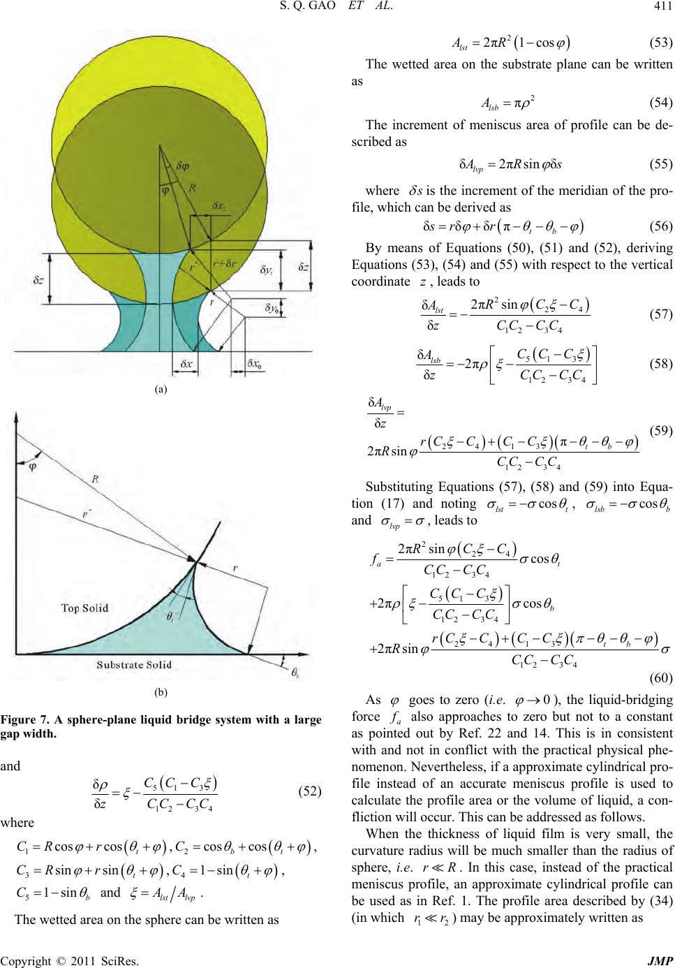 S. Q. GAO ET AL.411 (a) (b) Figure 7. A sphere-plane liquid bridge system with a large gap width. and 51 3 δCC C 12 34 δzCC CC (52) e wher 1coscos t CR r , cos bt2cosC , sinsin t CR r 3 , 41sint C , 51sinb C and lst lvp A . 2 2π1cos lst AR (53) The wetted area on the sub as strate plane can be written 2 π lsb A (54) The incremenniscus areaf profile can be de- sc t of me o ribed as δ2πsinδ lvp Rs (55) where is the increment of the meridian of the pro- file, which can be derived as b δδδπ t sr r (56) By means of Equations (50), (51) and (52), deriving Equations (53), (54) and (55) with respect to the vertical coordinate , leads to z 224 1 2πsin δ lst RCC A zCCCC (57) 2 34 δ The wetted area on the sphere can be written as 513 δlsb CC C A 12 34 2π δzC C CC (58) δlvp A 24 13 12 34 δ π 2πsin t z rC CCC RCC CC b Substituting Equations (57), (58) and (5 tion (17) and noting (59) 9) into Equa- cos lst t , cos lsb b and lvp , leads to 224 12 34 513 4 13 12 34 2πsin cos πsin at tb RCC fCC CC CC C C C RCC CC 12 34 2 2πcos 2 b CC CC rCC (60) As goes to zero (i.e. 0 ), the liquid-bridging force a also approachbut not to a constant as poted out by Ref. 22. This is in consisten with and not in conflict with the practical physical phe- nomenon. Nevertheless, if a approximate cylindrical pro- file instead of an accurate meniscus profile is used to calculate the profile area or the volume of liquid, a fli wr es to zero and 14 t con- in ctionill occur. This can be addessed as follows. When the thickness of liquid film is very small, the curvature radius will be much smaller than the radius of sphere, i.e. rR. In this case, instead of the practical meniscus profile, an approximate cylindrical profile can be used as in Ref. 1. The profile area described by (34) (in which rr) may be approximately written as 12 Copyright © 2011 SciRes. JMP 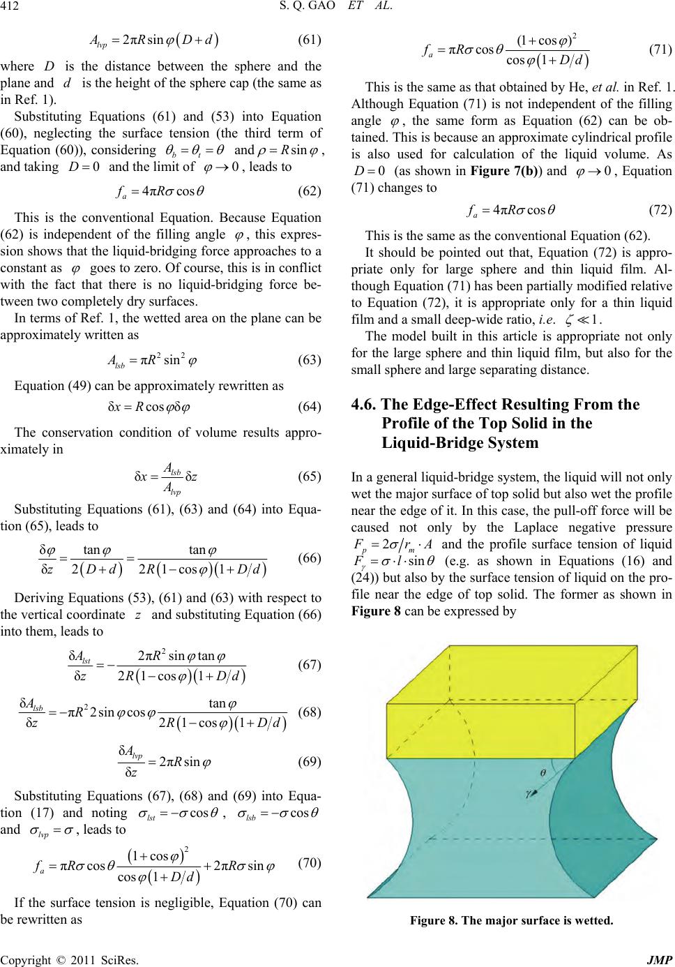 S. Q. GAO ET AL. 412 2πsin lvp RDd (61) where D is the distance between the sphere and the plane and d is the height of the sphere cap (the same as in Ref. 1). Substituting Equations (61) and (53) into Equation (60), neglecting the surface tension (the third term of Equation (6onsidering bt 0)), c andsinR , and taking and the limit of 0D 0 , leads to 4πcosfR a he p (62) This is t conventional Equation. Because Equation (62) is indeendent of the filling angle , this expres- sion shows that the liquid-bridging force approaches to a constant as goes to zero. Of course, this is in conflict with the fact that there is no liquridginge- tween two ctely dry surfaces. In terms of Re1, the wetted area id-b force b omple f. approximately written as on the plane can be 22 πsin lsb AR (63) Equation (49) can be appro ximately rewritten as δcos δxR (64) The conservation condition of volume results appro- ximately in δ Aδ lsb lvp z A (65) Substituting Equations (61), (63) tio and (64) into Equa- n (65), leads to δtan tan δ221cos1 zDdRDd uations (53), (61) and (63) with respect to the vertical coordinate and subs into them, leads to (66) Deriving Eqz titu ting Equ ation (66) 2 δ2πsin tan δ lst AR zR 21 c os 1Dd (67) 2 δtan π2sin cos δ21cos1 lsb R zRDd (68) δ2πsin AR δ lvp z (69) Substituting Equations (67), (68) and (6 tion (17) and noting 9) into Equa- cos lst , cos lsb and lvp , leads to 2 1cos πcos 2πsin cos 1 a fR R Dd ( If the surface tension is negligible be rewritten as 70) , Equation (70) can 2 (1cos ) πcos a fR ) cos1 Dd (71 This is the same as that obtained by He, et al. in Ref. 1. Although Equation (71) is not independent of th angle e filling , the same form as Equation (62) can be ob- tained. This is because an approximate cylindrical profile is also used for calculation of the liquid volume. As 0D ( as shown in Figure 7(b)) and 0 , Equation (71) changes to 4πcos a fR (72) on film a This is the same as the conventional Equation (62). It should be pointed out that, Equation (72) is appro- priate ly for large sphere and thin liquid film. Al- though Equation (71) has been partially modified relative to Equation (72), it is appropriate only for a thin liquid nd a small deep-wide ratio, i.e. 1 . The model built in this article is appropriate not only for the large sphere and thin liquid sm ive pressure film, but also for the all sphere and large separating distance. 4.6. The Edge-Effect Resulting From the Profile of the Top Solid in the Liquid-Bridge System In a general liquid-bridge system, the liquid will not only wet the major surface of top solid but also wet the profile near the edge of it. In this case, the pull-off force will be caused not only by the Laplace negat 2 pm rA and the profile surface tension of li sinFl quid (e.g. as shown in Equations (16) but also by the surface tension of liquid ear the edge of top solid. Th and on the pro- file ne former as shown in (24)) Figure 8 can be expressed by Figure 8. The major surface is wetted. Copyright © 2011 SciRes. JMP 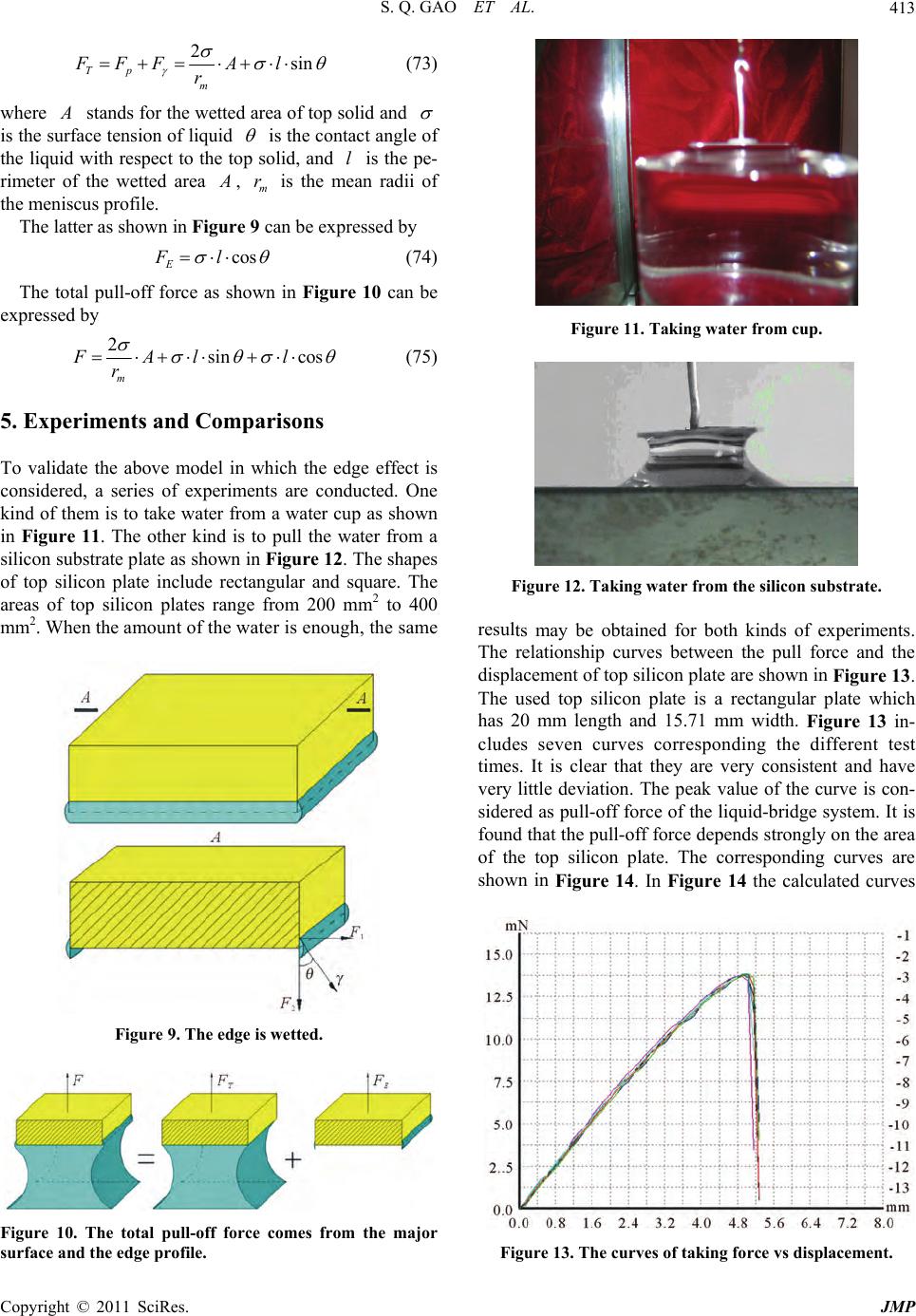 S. Q. GAO ET AL.413 2sin Tp m FFFA l r (73) where stands for the wetted area of top solid and is thsion of liquid e surface ten p is the contact angl the liquwith respect to the tosolid, and is th rime wetted area e of e pe- id ter of the l , m r is the m rad the mes profile. The latter as shown in Figure 9 can be expressed by eanii of niscu cos E Fl (74) The total pull-off force as shown in Figure 10 can be expressed by 2sin cos m FAl l r (75) 5. Exper To validate the above model in which the considered, a series of experiments are conducted. One thn . re an lates range from 200 mm to 400 me iments and Comparisons edge effect is kind ofem is to take water from a water cup as show in Figure 11. The other kind is to pull the water from a silicon substrate plate as shown in Figure 12The shapes of top silicon plate include ctgular and square. The areas of top silicon p2 m2. When the amount of the water is enough, the sam Figure 9. The edge is wetted. Figure 11. Taking water from cup. Figure 12. Taking water from the silicon substrate. both kinds of experiments. The relationship curves between the pull force and the displacement of top silicon plate are shown in Figure 13. The used top silicon plate is a rectangular plate which has 20 mm length and 15.71 mm width. Figure 13 in- cludes seven curves corresponding the different test times. It is clear that they are very consistent and have very little deviation. The peak value of the curve is con- sidered as pull-off force of the liquid-bridge system. It is found that the pull-off force depends strongly on the area of the top silicon plate. The corresponding curves are shown in Figure 14. In Figure 14 the calculated curves results may be obtained for Figure 10. The total pull-off force comes from the major surface and the edge profile. Figure 13. The curves of taking force vs displacement. Copyright © 2011 SciRes. JMP 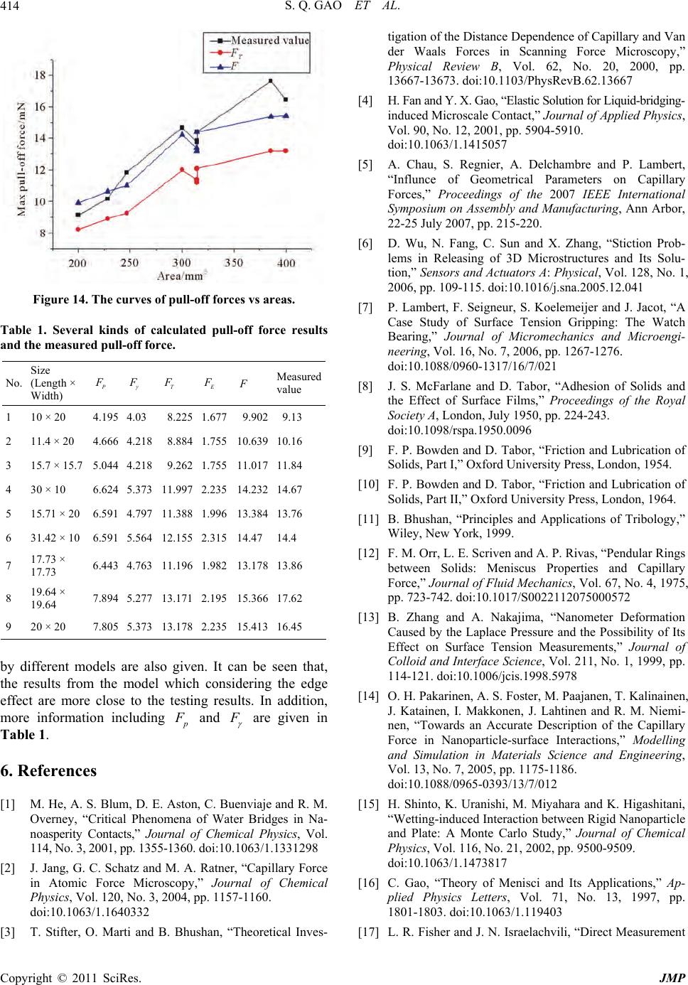 S. Q. GAO ET AL. 414 Figure 14. The curves of pull-off forces vs areas. Table 1. Several kinds of calculated pull-off force results and the measured pull-off force. No. Size (Length × Width) T Measured value 1 10 × 20 4.195 4.03 8.225 1.677 9.902 9.13 2 11.4 × 20 4.666 4.218 8.884 1.755 10.639 10.16 3 15.7 × 15.7 5.044 4.218 9.262 1.755 11.017 11.84 4 5 15.71 × 20 6.591 4.797 11.388 1.996 13.384 13.76 6 31.42 × 10 6.591 5.564 12.155 2.315 14.47 14.4 7 17.73 × 17.73 6.443 4.763 11.196 1.982 13.178 13.86 8 19.64 × 19.64 7.894 5.277 13.171 2.195 15.366 17.62 9 20 × 20 7.805 5.373 13.178 2.235 15.413 16.45 30 × 10 6.624 5.373 11.997 2.235 14.232 14.67 by different models are also given. It can be seen that, the results from the model which considering the edge effect are more close to the testing results. In add more information including ition, and are given Table 1. . R a of Water Bridges in Na- erity Contacts,” Journal of Chemical Phy , 200, pp. 55-1doi:10.1063/1. [2] G. C. Schatz and M. A. Ratner, “Capillary Force ic n 63 [Bes- of tran aals Frceicroy,” R Vpp. R [4] la ng- il te ics, 0, No. 12, 2001, pp. 5904-5910. 63 [5] au, S. Regnier, A. Delchambre and P. Lambert, e elary Forces,” Proceedings of the 2007 IEEE International Aal, , pp. 109-115. doi:10.1016/j.sna.2005.12.041 [7] P. Lambert, F. Seigneur, S. Koelemeijer and J. Jacot, “A f Surface Tension Gripping: The Watch al of Micromechanics and Microengi- l ation of niversity Press, London, 1954. 00572 eering, oparticle ,” Journal of Chemical ations,” Ap- . 71, No. 13, 1997, pp. t in [14] O. H. Pakarinen, A. S. Foster , M. Paaja nen, T. Kalina ine n, J. Katainen, I. Makkonen, J. Lahtinen and R. M. Niemi- nen, “Towards an Accurate Description of the Capillary Force in Nanoparticle-surface Interactions,” Modelling and Simulation in Materials Science and Engin 6eferences [1] M. He, A. S. Blum, D. E. Aston, C. Buenviaje and R. M. Overney, “Critical Phenomen noasp sics, Vol. 1331298 114, No. 3 J. Jang, 113 360. Phy in AtomForce Microscopy,” Joural of Chemical Physics, Vol. 12 doi:10.10 0, No. 3, 2004, p /1.164 p. 1157-1160. 0332 3] T. Stifter, O. Marti and . Bhushan, “Theoretical Inv tigation der Whe Dis orces tance D in S epende cannin nce of g FoCapilla My and V scop Physical eviewB, ol. 62, No. 20, 2000, 13667-13673. d Y. X. doi:10.1103 Ga /Phys stic Soluti evB.62.13667 on for H. Fan an induced M Vol. 9 o, “ELiquid-bridgi croscae Conact,” Journal of Applid Phys doi:10.10 A. Ch /1.1415057 “Influncof Gometrical Parameters on Capil Symposium on Assembly and Manufacturing, Ann Arbor, 22-25 July 2007, pp. 215-220. [6] D. Wu, N. Fang, C. Sun and X. Zhang, “Stiction Prob- lems in Releasing of 3D Microstructures and Its Solu- tion,” Sensors and Actuators: Physic Vol. 128, No. 1, 2006 Case Study o Bearing,” Journ neering, Vol. 16, No. 7, 2006, pp. 1267-1276. doi:10.1088/0960-1317/16/7/021 [8] J. S. McFarlane and D. Tabor, “Adhesion of Solids and the Effect of Surface Films,” Proceedings of the Roya Society A, London, July 1950, pp. 224-243. doi:10.1098/rspa.1950.0096 [9] F. P. Bowden and D. Tabor, “Friction and Lubric Solids, Part I,” Oxford U [10] F. P. Bowden and D. Tabor, “Friction and Lubrication of Solids, Part II,” Oxford University Press, London, 1964. [11] B. Bhushan, “Principles and Applications of Tribology,” Wiley, New York, 1999. [12] F. M. Orr, L. E. Scriven and A. P. Rivas, “Pendular Rings between Solids: Meniscus Properties and Capillary Force,” Journal of Fluid Mechanics, Vol. 67, No. 4, 1975, pp. 723-742. doi:10.1017/S00221120750 [13] B. Zhang and A. Nakajima, “Nanometer Deformation Caused by the Laplace Pressure and the Possibility of Its Effect on Surface Tension Measurements,” Journal of Colloid and Interface Science, Vol. 211, No. 1, 1999, pp. 114-121. doi:10.1006/jcis.1998.5978 Vol. 13, No. 7, 2005, pp. 1175-1186. doi:10.1088/0965-0393/13/7/012 [15] H. Shinto, K. Uranishi, M. Miyahara and K. Higashitani, “Wetting-induced Interaction between Rigid Nan and Plate: A Monte Carlo Study sics, Vol. 116, No. 21, 2002, pp. 9500-9509. doi:10.1063/1.1473817 [16] C. Gao, “Theory of Menisci and Its Applic plied Physics Letters, Vol 1801-1803. doi:10.1063/1.119403 [17] L. R. Fisher and J. N. Israelachvili, “Direct Measuremen Copyright © 2011 SciRes. JMP 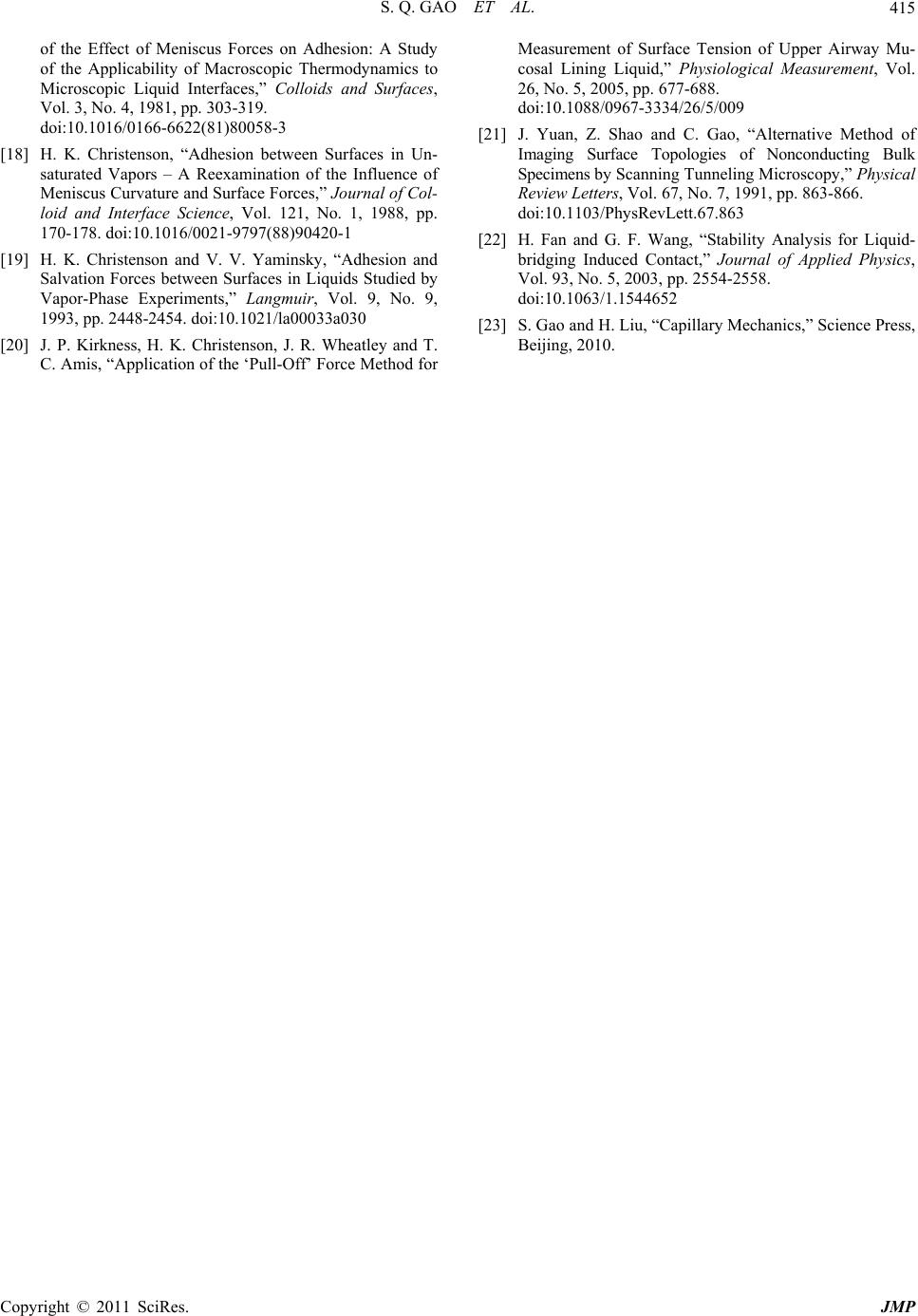 S. Q. GAO ET AL. Copyright © 2011 SciRes. JMP 415 of the Effect of Meniscus Forces on Adhesion: A Study of the Applicability of Macroscopic Thermodynamics to Meas Microscopic Liquid Interfaces,” Colloids and Surfaces, Vol. 3, No. 4, 1981, pp. 303-319. doi:10.1016/0166-6622(81)80058-3 [18] H. K. Christenson, “Adhesion between Surfaces in Un- saturated Vapors – A Reexamination of the Influence of Meniscus Curvature and Surface Forces,” Journal of Col- loid and Interface Science, Vol. 121, No. 1, 1988, pp. 170-178. doi:10.1016/0021-9797(88)90420-1 [19] H. K. Christenson and V. V. Yaminsky, “Adhesion and Salvation Forces between Surfaces in Liquids Studied by Vapor-Phase Experiments,” Langmuir, Vol. 9, No. 9, 1993, pp. 2448-2454. doi:10.1021/la00033a030 [20] J. P. Kirkness, H. K. Christenson, J. R. Wheatley and T. C. Amis, “Application of the ‘Pull-Off’ Force Method for urement of Surface Tension of Upper Airway Mu- cosal Lining Liquid,” Physiological Measurement, Vol. 26, No. 5, 2005, pp. 677-688. doi:10.1088/0967-3334/26/5/009 [21] J. Yuan, Z. Shao and C. Gao, “Alternative Method of Imaging Surface Topologies of Nonconducting Bulk Specimens by Scanning Tunneling Microscopy,” Physical Review Letters, Vol. 67, No. 7, 1991, pp. 863-866. doi:10.1103/PhysRevLett.67.863 [22] H. Fan and G. F. Wang, “Stability Analysis for Liquid- bridging Induced Contact,” Journal of Applied Physics, Vol. 93, No. 5, 2003, pp. 2554-2558. doi:10.1063/1.1544652 [23] S. Gao and H. Liu, “Capillary Mechanics,” Science Press, Beijing, 2010.
|