World Journal of Condensed Matter Physics, 2011, 1, 19-23
doi:10.4236/wjcmp.2011.12004 Published Online May 2011 (http://www.SciRP.org/journal/wjcmp)
Copyright © 2011 SciRes. WJCMP
19
On the Conduction Mechanism of Silicate Glass
Doped by Oxide Compounds of Ruthenium (Thick
Film Resistors)
Diffusion and Percolation Levels
Gulmurza Abdurakhmano v
The Institute of Power Engineering and Automation of the Uzbek Academy of Sciences, Tashkent, Uzbekistan.
Email: gulmirzo@mail.ru
Received March 15th, 2011; revised March 23rd, 2011; accepted March 25th, 2011.
ABSTRACT
The results of the investigation of conduction mechanism of silicate glass doped by oxide compounds of ruthenium
(thick film resistor) are reported. The formation of diffusion zones in the softened glass during firing process of the
mixture of the glass and the dopant powders is considered. As the result the doping glass becomes conductive. These
diffusion zones have higher conductivity and act as percolation levels fo r the free charge carriers. The effect of te mper-
ature and duration of firing process on the conductivity of doped glass is considered. Experimental results are in a
good agreement with the model.
Keywords: Lead-Silicate Glass, Thick Film Resistors , Percola tion Levels, Doping, Conductivity, Firing Conditions
1. Introduction
The silicate glass doped by oxide compounds of ruthe-
nium (DSG) and as a result becoming an electronic con-
ductor is a functional material in thick film resistors [1],
sensors [2] and electric heaters [3]. DSG is widely
known as thick film resistors (TFR) but this name does
not characterize DSG as a material. Despite the wide use
of DSG, the mechanism of electrical conduction is not
well understood yet.
For example variable range hopping, tunneling
through potential barrier, thermal activation, effective
medium approach and combinations of them have been
exploited [4-8] to explain the temperature dependence of
the DSG resistivity
( )
T
ρ
, schematically shown in Fig-
ure 1. Unfortunately these models can describe
( )
T
ρ
in
the narrow range of low temperatures (region I in Figure
1) only.
The quadratic temperature dependenc e
2
min
() ()m
TATT
ρρ
=−+
(1)
is observed often in DSG in the region II, where m
ρ
and min
Tare the resistivity and the temperature at the
min imu m.
The quadratic dependence (1) and region III we have
investigated here [9] do not correspond to any known
models of the electrical conductivity of DSG.
There are quite a few questions which can not be un-
derstood in the framework of the above-mentioned mod-
els: how size and conductivity of the dopant particles
affect the conductivity of DSG, the mechanism by which
it is affected by temperature f
T and the duration
τ
of
the firing on the room temperature value 0
ρ
and slope
of the
()
T
ρ
, why the glass composition affects the
conduction of the DSG, why the percolation threshold on
the
( )
C
ρ
shift or disappearance for glass of various
content and etc. The
( )
dd
g
VCV V+= here is the vo-
lume fraction of the dopant in DSG or the doping level,
d
V
and g
V
- volumes of the dopant and the glass accor-
dingly, 0dg
=+ is the total volume of the specimen.
We examine these questions while ignoring th e role of
the glass in conductance of the DSG. In fact at standard
firing conditions (firing temperature f
1123K
T
) the
lead-silicate glass softens and becomes very aggressive
substance, enable to solve appreciable amounts of oxides
of many metals (units or tens of %) [10]. So long as fir-
On the Conduction Mechanism of Silicate Glass Doped by Oxide Compounds of Ruthenium (Thick Film Resistors)
Copyright © 2011 SciRes. WJCMP
20
0
77
300
500
1000
1
10
T, K
R
R
0
I
II
III
Figure 1. Resistivity vs temperature for DSG (schematical-
ly). Regi ons I , II and I II cor r e spond to low , middle and hi gh
temperature.
ing duration of DSG is limited (usually
10min
τ
) and
mechanical mixing is not affecting the distribution of
solved atoms of the dopant in the glass, it should be dif-
fusive.
In this paper we will consider a possible effect of dif-
fusion of dopant atoms at f
T in the glass on the elec-
trical conduction of the DSG.
The production of specimens is a standard procedure
for thick film resistors and is described in many papers
and books (see, for example, [2]). The glass composi-
tions we us ed are as follows (weight %):
Glass1 SiO2 31; PbO 67; MnO2 2;
Glass2 SiO2 29; PbO 67; BaO 4.
The DSG specimens compositions are as follows
(weight %):
1) Glass1 80; Pb2Ru2O6 20;
2) Glass1 90; RuO2 10;
3) Glass2 90; RuO2 10;
4) Glass2 80; RuO2 20.
Volume fraction of dopant C is less than theoretical
percolation threshold (critical value Cc) in all cases.
2. Diffusion of Dopant Atoms into the Glass
and Formation of Percolation Levels
It should be noted that the percolation theory is consi-
dered as most common model of conduction mechanism
of the DSG [11-13]. In this theory transport of charge
takes place along the contiguous chains of intimately
contacted dopant particles (infinite cluster) and the resis-
tivity of DSG depends on the dopant volume fraction C
as
( )
( )
0C
t
C CC
ρρ
= −
(2)
where 0
ρ
is material-dependent prefactor,
C
C
is the
percolation critical volume fraction of the dopant below
which
ρ
goes to infinity,
t
is the dc transport critical
exponent. According to the standard theory of transport
percolation [12], C
C≈ 0.12 0.39 and 01.6 2tt ÷ is
the universal value for three-dimensional disordered
composites.
The expression (2) predicts percolation threshold of
( )
C
ρ
at C
CC
, while in reality the value of
t
might
be as high as 7 for various compositions of glass and
doping conditions [14]. Additionally, the value of C
C is
essentially lower than the theoretical estimation in many
cases or percolation threshold disappears .
The reason for this discrepancy between the experi-
mental results and the theory of percolation is the as-
sumption that the volume fraction
C
of the dopant in
the DSG (after firing) is known a priori (often it equals
to the initial volume fraction of them). In fact the interac-
tion of dopant and the glass is possible during the firing
process as well as the mutual diffusion of the glass and
dopant atoms. As the result one does not have informa-
tion about C in the final stage of technological process
and about the value of the resistivity of doped region s of
the glass. So we should consider that the glass resistivity
(in the diffusion zone) is reduced by many orders of
magnitude due to diffusion (as in crystalline semicon-
ductors) and infinite cluster consists of closed or over-
lapping diffusion zones which have been formed around
the each dopant particle (Figure 2).
Let us to consider [15] that the diffusion zone is
spherical because the glass is isotropic. This diffusion
zone has the volume
3
dd
4
3R
V
π
=
(3)
There
dd
R rl= +is the radius of the diffusion zone,
r
is the main radius of the dopant particles, and the dif-
fusion length is
d
d0
f
exp 2
E
lDD kT
ττ

= =−


. (4)
There
D
is the diffusion coefficient,
( )
0f
D DT= →∞
,
d
E
is the activation energy of diffusion, and
k
is the
Boltzmann constant. Inserting
Figure 2. Formation of diffusion zone around the dopant
particle of the radius r. There r + ld is the radius of diffusion
zone, ld is the diffusion length. L is the main distance be-
tween the nei gh bor dopant particles in the DSG.
d
rl+
L
r
On the Conduction Mechanism of Silicate Glass Doped by Oxide Compounds of Ruthenium (Thick Film Resistors)
Copyright © 2011 SciRes. WJCMP
21
( )
ddg
C VVV=+ and
( )
cd
cg
CVVV=+ into (2) and
taking into account (3) and (4) gives
( )
( )
1/
0
00
d0
f
3
ln /
4
1ln( ).
22
t
c
VVV r
ED
kT
ρρ
τ


+ −=


π


−+
(5)
Expression (5) for
f
()T
ρ
of DSG is in a good
agreement with experiment (Figure 3) for various
glasses and dopants and makes it possible to evaluate0
D,
d
Eand
d
l
from the experimental data. Here 0
ρ
is the
fitting parameter and corresponds to average resistivity
of the diffusion zone, which is unknown and is usually
no uniform. The value of the diffusion length d
l0.22
1600 μm, evaluated in the same manner for the standard
firing conditions is essentially higher than the main dis-
tance between dopant particles
d1
33
2 211
66
gm
Lr r
CC
γ
γ


ππ
== +−





(6)
From (6) we have
0.16L
μm for main diameter
2 0.1r
μm of dopant particles and volume fraction
0.16C
, so diffusion zones are heavily overlapped and
the whole volume of the specimen is uniformly filled by
infinite conductive cluster, as shown schematically in
Figure 4. There d
γ
and g
γ
are the specific weight of do-
pant and glass accordingly, m
Cis the mass fraction of
the dopant.
(a)
(b)
Figure 3. R(Tf) for DSG mentioned above (see Introduction).
Solid lines are fitting of (5) to experimental data by the least
squires me t hod .
Figure 4. Generation of percolation levels due to diffusion
(schematically). The bold curve is the infinite cluster. Gray
circles represent diffusion zones. Tf in 3 is higher than in 1.
τ
=
const.
Expression (5) shows good agreement with the expe-
rimental data for DSG of other compositions [16] as well
(Figure 5).
One can also derive the effect of firing duration
τ
on
the resistivity
ρ
of DSG from (2) – (4):
( )
( )
2
1
00
f
13
34
t
c
V Vr
DT
τ ρρ


= +−


π


(7)
This expression is compared with the experiment in
Figure 6.
We have simulated the effect of doping level and size
of dopant particles on the
ρ
of DSG. The simulation is
based on Fick’s equation [17] and expression (5). It is
assumed that 1) diffusion from neighbor particles of the
dopant into the glass interlayer is uniform; 2) value of
ρ
is predetermined by minimum of concentration N of
dopant atoms at the middle point being at distance L/2
from each of them, i.e.,
( )
12N xL
ρ
∝=
.
The result of the simulation of
( )
ρτ
for two sizes of
dopant particles is shown in Figure 7. It is clear on one
hand that the size of dopant particles essentially affects
on the conductivity of DSG. On the other hand
( )
R
τ
at
small
τ
is stronger in our simulation than in the usual
model of diffusion
( )
( )
expRc
ττ
∝−
(the last is
shown in Figure 7 as dotted line).
Resistivity of DSG is strongly affected by the dispersiv-
ity of the dopant powder [16] reduction of the di-ameter
of the particles from 4.5 μm up to 1.6 μm decreases
1
2
3
On the Conduction Mechanism of Silicate Glass Doped by Oxide Compounds of Ruthenium (Thick Film Resistors)
Copyright © 2011 SciRes. WJCMP
22
8.0
8.5
9.0
9.5
1.5
1.0
0.5
0.0
104
T
f
,K
1
lg

R
R
0
1
t
V
c
Figure 5. R(Tf), recalculated data from [16] in accordance
with (5). The solid line is fitting of (5) with R0 = 10 Ohm, t =
1.7, Vc = 0.16.
1
2
3
4
1.0
1.5
2.0
2.5
3.0
3.5
4.0
0.06
0.07
0.08
0.09
0.1
0.11
0.12
0.13
0.14
0.15
,
min
R
1
t
,
kOhm
Figure 6. R(τ) for DSG at Tf , K: 1073 (1, 2) and 1123 (3, 4).
Temperature increasing rate is higher for data 1 and 2,
than for data 3 and 4. Points are recalculated from [16] in
accordance with (7). DSG composition isn’t varied.
a
b
c
0.5
1.0
1.5
2.0
2.5
3.0
0
2
4
6
8
D
,ar b.unit
lg
R

R
0
Figure 7. The result of simulation
( )
R
τ
of DSG for r, μm:
0.5 (a); 1 (b).
L
5 μm. The function
( )
expab c
τ
+−
(dotted li ne) have been fitte d to curve a in the 3 points.
the resistivity by bout one order in magnitude.
We have simulated this effect as the result of diffusion
a
b
0.1
0.2
0.3
0.4
0.5
0.6
0.7
3.5
3.0
2.5
2.0
1.5
1.0
0.5
0.0
r,
m
lg
N
r

N
0
Figure 8. Effect of the main size of dopant particles on con-
centration of the dopant atoms at the point
2 2.5xL= =
μm
between the neighbor dopant particles (simulation, see Fig-
ures 2 and 7). Content of dopant in DSG is 2 times less for
curve a than for curve b. The diffusion duration accords to
the diffusion lengthD
τ
=1,25 μm.
process (Figure 8) in accordance with the expression (5)
for two val ues of c
CC
<. There we assume that
( )
12N xL
ρ
∝=
, the same assumption is made in fig.
7. One can see that the dependence
( )
r
ρ
or
( )
,2Nrx L=
becomes stronger for smaller
r
, when
the main distance between particles of the dopant have
been decreased for constant C, and conductivity of the
DSG increases.
It must be noted here that the information on the solu-
bility of RuO2 in lead-sili cate glass is contr adictory: Pala-
nisamy et al. [18] estimate it less than 10-4 atomic %,
while Flachbart et al. [8] present the value about 7 atom-
ic %. We are inclined to admit the last value because of
the results of X-ray diffraction experiments, in which the
intensity of main reflexes of RuO2 relicts in DSG reduces
nearly 10% due to firing and they become wider [19].
One should also take into account the fact that solubility
of pure metals in silicate glass is very small (really less
than 10-3 atomic%, [20]), while solubility of their oxides
is essentially higher (up to 10 – 70 mol . % for PbO).
It is clear in the same approach that the electrical
properties of DSG, specifically
( )
T
ρ
, beyond the forma-
tion of infinite cluster from diffusion zones, mainly de-
pend on the properties of the doped glass, namely, on the
glass structure, on the distribution of the energy levels of
the impurity in the energy gap of the glass, and on other
microscopic characteristics.
The resistivity of the glass in the diffusion zone is 5 - 6
orders of magnitudes higher than that of the dopant re-
licts, so the latter one does not affect the macroscopic
parameters of the DSG unless they form an infinite clus-
ter (i.e. unless c
CC
<). Indeed, th e conduction is metal-
lic at c
CC
>.
3. Conclusions
The experiments and simulations show that the diffusion
zones are formed around the dopant particles in DSG due
On the Conduction Mechanism of Silicate Glass Doped by Oxide Compounds of Ruthenium (Thick Film Resistors)
Copyright © 2011 SciRes. WJCMP
23
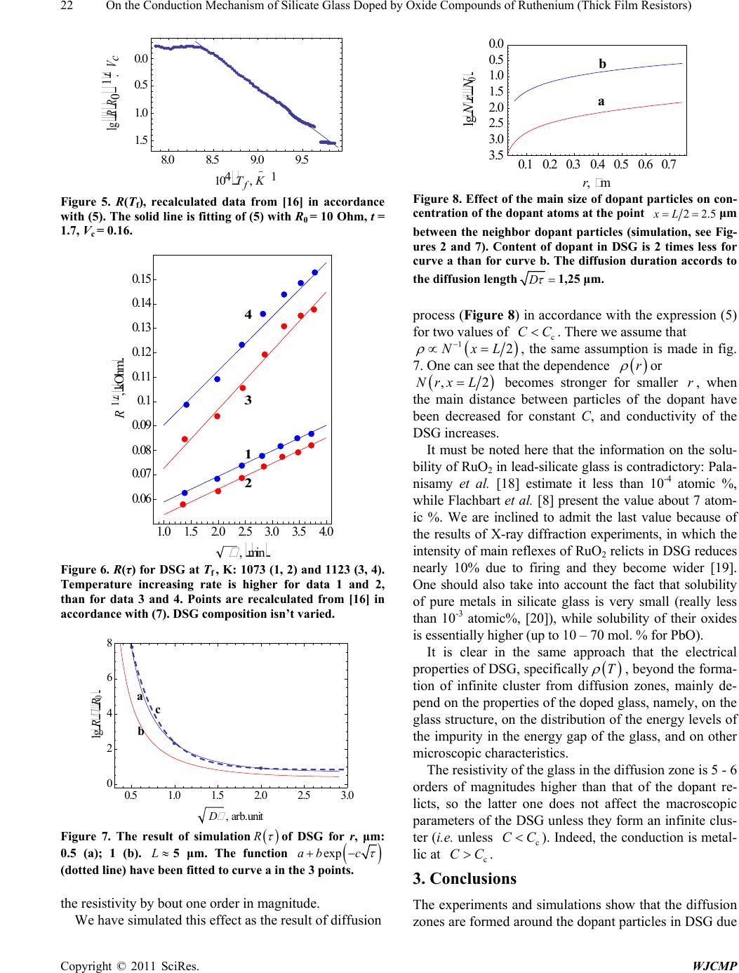
to the diffusion of dopant atoms into the glass during the
firing. The glass becomes conductive in these zones and
the overlapping of them generates the infinite conductive
cluster (s) (percolation levels). This model allows ex-
plaining the effect of technological parameters such as
temperature and duration of firing, glass and dopant
composition, dispersivity of the powders, on the electric-
al properties of the DSG as well as the absence of perco-
lation threshold or its shift to smaller values of the do-
pant content
4. Acknowledgements
Fond for Support of Fundamental Researches of the Uz-
bek Academy of Sciences is acknowledged for the finan-
cial support (grants 55-08 and 27-10).
REFERENCES
[1] H. C. Angus and P. E. Gainsbury, “Glaze Resistors with
Ruthenium Dioxide,” Electronic Components, Vol . 9, No.
1, 1968, p. 84.
[2] M. Prudenziati, “Thick Film Sensors,” Elsevier Science,
Amsterdam, 1994.
[3] Thick Film Heating Technology, www.watlow.com.
[4] G. E. Pike and C. H. Seager, “Electrical Properties and
Conduction Mechanisms of Ru-Based Thick-Film (Cer-
met) Resistors,” Journal of Applied Physics, Vol. 48, No.
12, 1977, p. 5152. doi:10.1063/1.323595
[5] D. P. H. Smith and J. C. Anderson, “Electron Conduction
in Thick Film Resistors,” Thin Solid Films, Vol. 71, No. 1,
1980, pp. 79-89. doi:10.1016/0040-6090(80)90186-8
[6] A. Abe and Y. Taketa, “Electrical Conduction in Thick
Film Resistors,” Journal of Physics D: Applied Physics,
Vol. 24, No. 7, 1991, p. 1163.
[7] W. Schoepe, “Conduction Mechanism in Granular RuO2-
Based Thick-Film Resistors,” Physica B: Physics of Con-
densed Matter, Vol. 165, 1990, pp. 299-300.
[8] K. Flachbart, V. Pavlнk, N. Tomašovičová, C. J. Adkins,
M. Somora, J. Leib and G. Eska, “Conduction Mechan-
ism in RuO2-Based Thick Films,” Physica Status Solidi
(B), 205, No. 1, January 1998, pp. 399-404.
doi:10.1002/(SICI)1521-3951(199801)205:1<399::AID-P
SSB399>3.0.CO;2-X
[9] G. Abdurakhmanov and N. G. Abdurakhmanova, “High
Temperature Anomalies in Resistivity and Thermoelectric
Power of Thick Film Resistors,” Physica Status Solidi (A),
Vol. 202, No. 9, 2005, pp. 1799-1803.
doi:10.1002/pssa.200420036
[10] A. A. Appen, “Khimiya stekla (Chemistry of Glass, in
Russian) Leningrad,Khimiya Publishing House, Lenin-
grad Branch, 1974.
[11] V. L. Bonch-Bruevich, et al., “Electron Theory of Disor-
dered Semi Conductors (in Russian),” Nauka Publishers,
Мoscow, 1981.
[12] B. I. Shklovskii and A. L. Efros, “Electronic Properties of
Doped Semiconductors,” Springer, Heidelberg, 1984.
[13] J. Ziman, “Models of Disorder,” Cambridge University
Press, Cambridge, 1979.
[14] C. Grimaldi, T. Maeder, P. Ryser and S. Strässler, “A
Model of Transport Non-Universality in Thick-Film Re-
sistors,” Applied Physics Letters, Vol. 83, 2003, p. 189.
[15] G. Abdurakhmanov and G. S. Vakhidova, “Diffusion and
Electrical Conduction in Thick Film Resistors,” Technical
Physics, The Russian Journal of Applied Physics, Vol. 65,
No. 7, 1995, p. 178.
[16] J. Lee and R. W. West, “Firing Studies with Model Thick
Film Resistor Systems,” IEEE Transactions on Compo-
nents, Hybrids and Manufacturing Technology, Vol. 6,
No. 4, 1983, p. 430.
[17] J. P. Stark, “Solid State Diffusion,” Wiley, New York,
1976.
[18] P. Palanisamy, D. H. R. Sarma and R. W. Ves t , “Solubil-
ity of Ruthenium Dioxide in Lead Borosilicate Glasses,”
Journal of the American Ceramic Society, Vol. 72, No. 9,
September 1989, pp. 1755-1756.
doi:10.1111/j.1151-2916.1989.tb06321.x
[19] G. Abdurakhmanov, G. Vakhidova and L. Tursunov,
Interaction of RuO2 and Lead-Silicate Glass in Thick-
Film Resistors,” World Journal of Condensed Matter
Physics, Vol. 1, No. 1, February 2011, pp. 1-5.
[20] H. D. Schreiber, F. A. Settle, P. L. Jamison, J. P. Ecke-
nrode and G. W. Headley, “Ruthenium in Glass—Form-
ing Borosilicate Melts,” Journal of the Less Common
Metals, Vol. 115, No. 1, January 1986, pp. 145-154.
doi:10.1016/0022-5088(86)90379-6