Paper Menu >>
Journal Menu >>
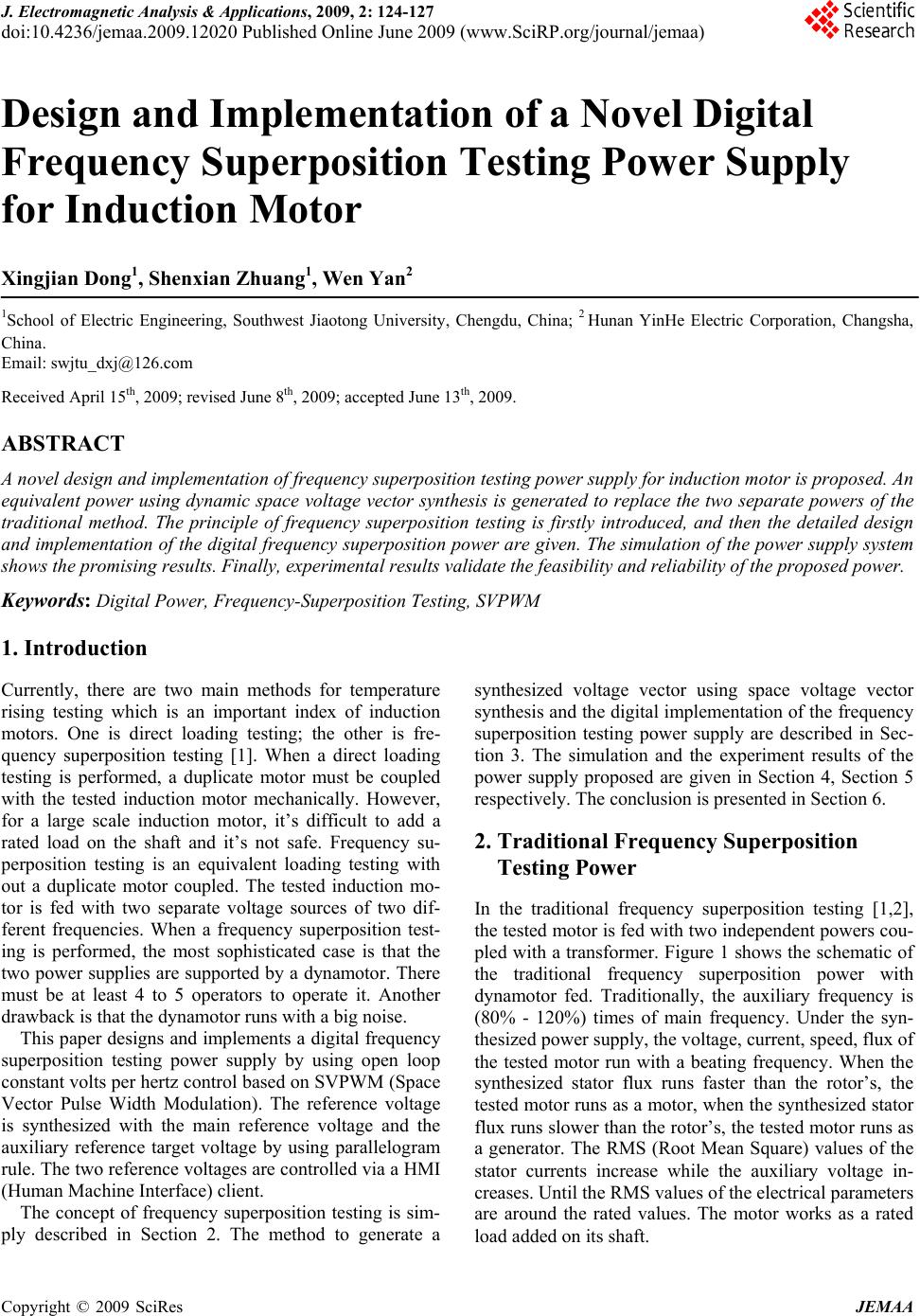 J. Electromagnetic Analysis & Applications, 2009, 2: 124-127 doi:10.4236/jemaa.2009.12020 Published Online June 2009 (www.SciRP.org/journal/jemaa) Copyright © 2009 SciRes JEMAA 1 Design and Implementation of a Novel Digital Frequency Superposition Testing Power Supply for Induction Motor Xingjian Dong1, Shenxian Zhuang1, Wen Yan2 1School of Electric Engineering, Southwest Jiaotong University, Chengdu, China; 2 Hunan YinHe Electric Corporation, Changsha, China. Email: swjtu_dxj@126.com Received April 15th, 2009; revised June 8th, 2009; accepted June 13th, 2009. ABSTRACT A novel design and implementation of frequency superposition testing power supply for induction motor is proposed. An equivalent power using dynamic space voltage vector synthesis is generated to replace the two separate powers of the traditional method. The principle of frequency superposition testing is firstly introduced, and then the detailed design and implementation of the digita l frequency superpositio n power are given. Th e simulation of the power supply system shows the promising resu lts. Finally, experimental results validate the feasibility and reliability of the proposed power. Keywords: Digital Power, Frequency-Superposition Testing, SVPWM 1. Introduction Currently, there are two main methods for temperature rising testing which is an important index of induction motors. One is direct loading testing; the other is fre- quency superposition testing [1]. When a direct loading testing is performed, a duplicate motor must be coupled with the tested induction motor mechanically. However, for a large scale induction motor, it’s difficult to add a rated load on the shaft and it’s not safe. Frequency su- perposition testing is an equivalent loading testing with out a duplicate motor coupled. The tested induction mo- tor is fed with two separate voltage sources of two dif- ferent frequencies. When a frequency superposition test- ing is performed, the most sophisticated case is that the two power supplies ar e supported by a dynamotor. There must be at least 4 to 5 operators to operate it. Another drawback is that the dynamotor runs with a big noise. This paper designs and implements a digital frequency superposition testing power supply by using open loop constant volts per hertz control based on SVPWM (Space Vector Pulse Width Modulation). The reference voltage is synthesized with the main reference voltage and the auxiliary reference target voltage by using parallelogram rule. The two reference voltages are controlled via a HMI (Human Machine Interface) client. The concept of frequency superposition testing is sim- ply described in Section 2. The method to generate a synthesized voltage vector using space voltage vector synthesis and the digital implementation of the frequency superposition testing power supply are described in Sec- tion 3. The simulation and the experiment results of the power supply proposed are given in Section 4, Section 5 respectively. The conclusion is presented in Section 6. 2. Traditional Frequency Superposition Testing Power In the traditional frequency superposition testing [1,2], the tested motor is fed with two independent powers cou- pled with a transformer. Figure 1 shows the schematic of the traditional frequency superposition power with dynamotor fed. Traditionally, the auxiliary frequency is (80% - 120%) times of main frequency. Under the syn- thesized power supply, the voltage, curren t, speed , flux of the tested motor run with a beating frequency. When the synthesized stator flux runs faster than the rotor’s, the tested motor runs as a motor, when the synthesized stator flux runs slower than the rotor’s, the tested motor runs as a generator. The RMS (Root Mean Square) values of the stator currents increase while the auxiliary voltage in- creases. Until the RMS values of the electrical parameters are around the rated values. The motor works as a rated load added on its shaft. 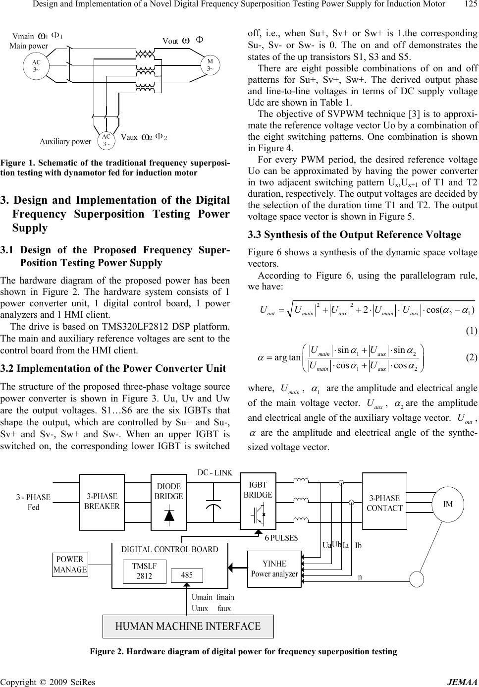 Design and Implementation of a Novel Digital Frequency Superposition Testing Power Supply for Induction Motor 125 Figure 1. Schematic of the traditional frequency superposi- tion testing with dynamotor fed for induction motor 3. Design and Implementation of the Digital Frequency Superposition Testing Power Supply 3.1 Design of the Proposed Frequency Super- Position Testing Power Supply The hardware diagram of the proposed power has been shown in Figure 2. The hardware system consists of 1 power converter unit, 1 digital control board, 1 power analyzers and 1 HMI client. The drive is based on TMS320LF2812 DSP platform. The main and auxiliary reference voltages are sent to the control board from the HMI client. 3.2 Implementation of the Power Converter Unit The structure of the proposed three-phase voltage source power converter is shown in Figure 3. Uu, Uv and Uw are the output voltages. S1…S6 are the six IGBTs that shape the output, which are controlled by Su+ and Su-, Sv+ and Sv-, Sw+ and Sw-. When an upper IGBT is switched on, the corresponding lower IGBT is switched off, i.e., when Su+, Sv+ or Sw+ is 1.the corresponding Su-, Sv- or Sw- is 0. The on and off demonstrates the states of the up transistors S1, S3 and S5. There are eight possible combinations of on and off patterns for Su+, Sv+, Sw+. The derived output phase and line-to-line voltages in terms of DC supply voltage Udc are shown in Table 1. The objective of SVPWM technique [3] is to approxi- mate the reference voltage vector Uo by a combination of the eight switching patterns. One combination is shown in Figure 4. For every PWM period, the desired reference voltage Uo can be approximated by having the power converter in two adjacent switching pattern Ux,Ux+1 of T1 and T2 duration, respectively. The output voltages are decided by the selection of the duration time T1 and T2. The output voltage space vector is shown in Figure 5. 3.3 Synthesis of the Output Reference Voltage Figure 6 shows a synthesis of the dynamic space voltage vectors. According to Figure 6, using the parallelogram rule, we have: 22 21 2cos( outmainauxmain aux UU UUU) (1) 1 12 sin sin arg tancos cos main aux main aux UU UU 2 (2) where, , main U1 are the amplitude and electrical angle of the main voltage vector. , aux U2 are the amplitude and electrical angle of the auxiliary voltage vector. , out U are the amplitude and electrical angle of the synthe- sized voltage vector. Figure 2. Hardware diagram of digital power for frequency superposition testing Copyright © 2009 SciRes JEMAA 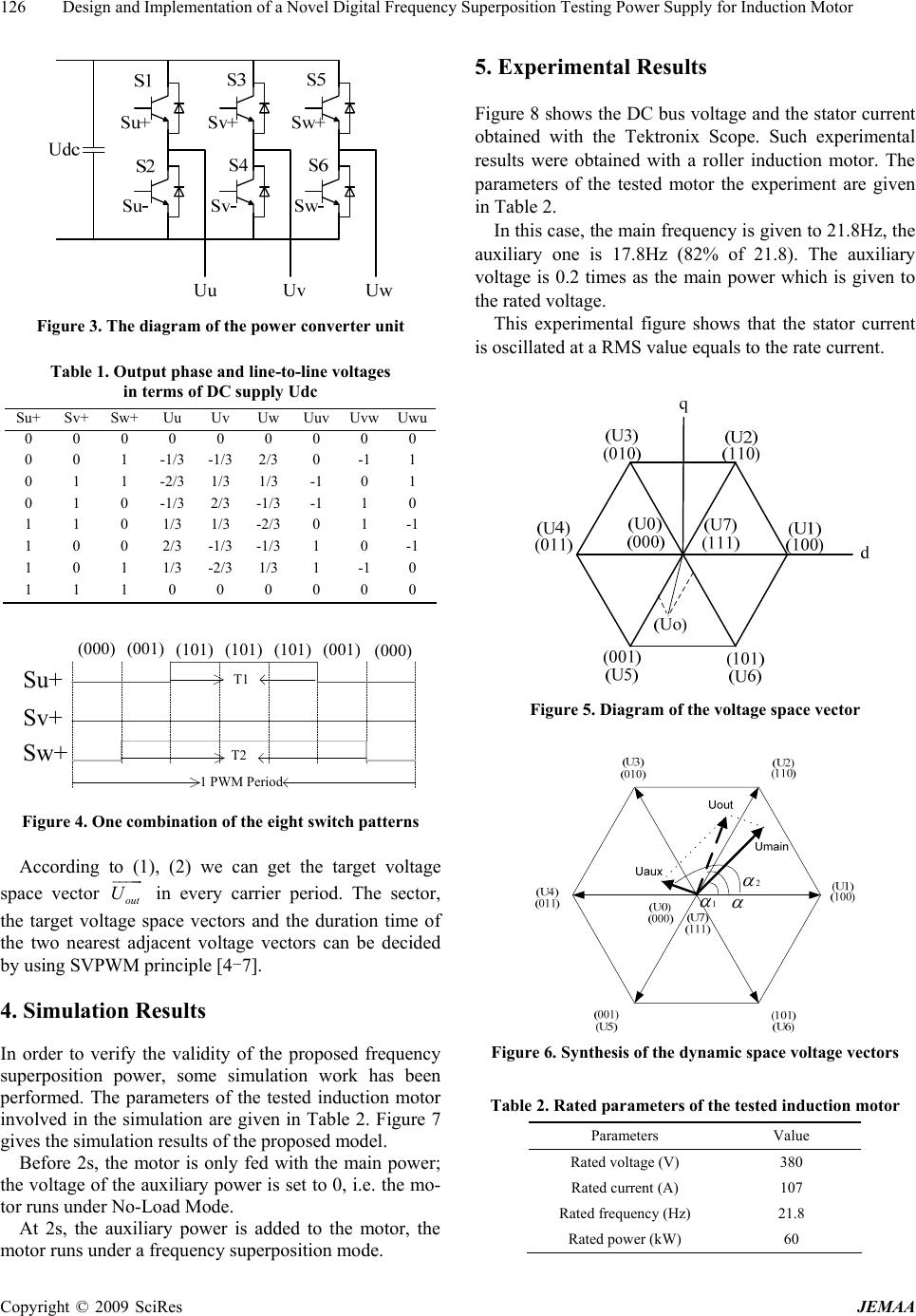 126 Design and Implementation of a Novel Digital Frequency Superposition Testing Power Supply for Induction Motor Figure 3. The diagram of the power converter unit Table 1. Output phase and line-to-line voltages in terms of DC supply Udc Su+ Sv+ Sw+ Uu UvUw Uuv UvwUwu 0 0 0 0 0 0 0 0 0 0 0 1 -1/3 -1/32/3 0 -1 1 0 1 1 -2/3 1/3 1/3 -1 0 1 0 1 0 -1/3 2/3-1/3 -1 1 0 1 1 0 1/3 1/3-2/3 0 1 -1 1 0 0 2/3 -1/3-1/3 1 0 -1 1 0 1 1/3 -2/31/3 1 -1 0 1 1 1 0 0 0 0 0 0 (000) (001) (101) (101) (101) (001)(000) Su+ Sv+ Sw+ 1 PWM Period T2 T1 Figure 4. One combination of the eight switch patterns According t1), (2) we can get the target voltage space vector in every carrier period. The sector, the target voltage space vectors and the duration time of the two nearest adjacent voltage vectors can be decided by using SVPWM principle [4-7]. o ( out U 4. Simulation Results In order to verify the validity of the proposed frequency superposition power, some simulation work has been performed. The parameters of the tested induction motor involved in the simulation are given in Table 2. Figure 7 gives the simulation results of the proposed m odel. Before 2s, the motor is only fed with the main power; the voltage of the auxiliary power is set to 0, i.e. the mo- tor runs under No-Load Mode. At 2s, the auxiliary power is added to the motor, the motor runs under a frequency superposition mode. 5. Experimental Results Figure 8 shows the DC bus voltage and the stator current obtained with the Tektronix Scope. Such experimental results were obtained with a roller induction motor. The parameters of the tested motor the experiment are given in Table 2. In this case, the main frequency is given to 21.8Hz, the auxiliary one is 17.8Hz (82% of 21.8). The auxiliary voltage is 0.2 times as the main power which is given to the rated voltage. This experimental figure shows that the stator current is oscillated at a RMS value equals to the rate current. Figure 5. Diagram of the voltage space vector 1 2 Figure 6. Synthesis of the dynamic space voltage vectors Table 2. Rated parameters of the tested induction motor Parameters Value Rated voltage (V) 380 Rated current (A) 107 Rated frequency (Hz) 21.8 Rated power (kW ) 60 Copyright © 2009 SciRes JEMAA  Design and Implementation of a Novel Digital Frequency Superposition Testing Power Supply for Induction Motor 127 Figure 7. Simulation results of the stator phase A current and the DC bus voltage Figure 8. Experimental results of the proposed frequency superposition power supply 6. Conclusions In this paper, a design of digital motor drive for fre- quency superposition testing is proposed. It has been im- plemented in an open loop control by using digital signal processor TMS320LF2812. Simulation results show that the stator current oscillated at a beating frequency after Frequency-Superposition. The tested motor runs as a rated load coupled with it. The experimental results indi- cate that this power supply can realize the equivalent loading test. REFERENCES [1] I. Boldea and A. A. Nasar, “The induction machine hand- book,” CRC, Boca Raton, Florida, 2002. [2] H. R. Schwenk, “Equivalent loading of induction machine for temperature tests,” IEEE Transactions on Power Ap- paratus and Systems, Vol. 96, No. 4, PP. 1126-1131, 1977. [3] V. Vlatkovic and D. Borojevic, “Digi- tal-signal-processor-based control using the constant V/F principle and a space-vector PWM algorithm,” IEEE Transactions on Industrial Electronics, Vol. 41, No. 3, pp. 326-332, 1997. [4] H. W. van der Broeck, H. C. Skudelny and G. V. Stanke, “Analysis and realization of a pulse width modulator based on voltage space vectors,” IEEE Transactions on Industrial Application, Vol. 24, No. 1, pp. 142-150, 1988. [5] Y.-Y. Tzou and H.-J. Hsu, “FPGA realization of space vector PWM control IC for 3 phase PWM inverters,” IEEE Transactions on Power Electronics, Vol. 12, No. 6, pp. 953-963, 1997. [6] K. L. Zhou and D. W. Wang, “Relationship between space-vector modulation and three-phase carrier-based PWM: A comprehensive analysis,” IEEE Transactions on Industrial Electronics, Vol. 49, No. 1, pp. 186-192, 2002. [7] Timothy and Skvarenina, “The power electronics hand- book,” CRC, Boca Raton, Florida, 2002. Copyright © 2009 SciRes JEMAA |