Circuits and Systems
Vol.07 No.09(2016), Article ID:69249,18 pages
10.4236/cs.2016.79228
Modeling and Analysis of Variable Frequency Inverted Sine PWM Technique for a Hybrid Cascaded Multilevel Inverter
M. Sudhakaran1, R. Seyezhai2
1Department of Electrical and Electronics Engineering, Ganadipathy Tulsi’s Engineering College, Vellore, India
2Department of Electrical and Electronics Engineering, SSN College of Engineering, Kalavakkam, Chennai, India

Copyright © 2016 by authors and Scientific Research Publishing Inc.
This work is licensed under the Creative Commons Attribution International License (CC BY).
http://creativecommons.org/licenses/by/4.0/


Received 7 April 2016; accepted 25 April 2016; published 28 July 2016
ABSTRACT
In cascaded H-bridge multilevel inverter, a variable frequency inverted sine PWM technique is modeled for hybrid electric vehicles. It has a particular advantage of increasing power which is achieved using series connection of H-bridge and also this topology is capable to produce superior spectral quality with considerable improvement of fundamental voltage. The variable frequency inverted sine PWM technique produces lesser torque ripple and enhances the fundamental output voltage mainly at lower modulation index ranges. The topologies of multilevel inverter are flying capacitor, diode clamped and cascaded inverter. In the paper, we will discuss about the cascaded multilevel inverter based on inverted sine PWM technique. The two switching strategies widely used to control multilevel inverters are constant frequency inverted sine PWM (CF-ISPWM) and variable frequency inverted sine PWM (VF-ISPWM). This implies that switch utilization substantially reduces 32.35% of the constant frequency inverted sine PWM switching technique. The performance of the technique is validated in terms of Total Harmonic Distortion (THD) and Torque ripple which significantly reduces when compared to constant frequency ISPWM. The analysis of conventional triangular PWM inverter and inverted sine PWM inverter using constant and variable switching scheme is done in MATLAB Simulink and verified experimentally by FPGA Spartan 3E processor.
Keywords:
Cascaded Multilevel Inverter, Constant Frequency Inverted Sine PWM, Variable Frequency Inverted Sine PWM, Total Harmonic Distortion

1. Introduction
Power Electronics based inverters are widely used in many industrial, aerospace and military applications because of their incredible concert on control capability and energy saving. Multi Level Inverter (MLI) is an attractive topology for high voltage DC-AC conversion. The reliability of power electronics system is directly related to the security of motor drive systems. The function of a multilevel inverter is to synthesize a desired staircase output waveform from several levels of dc input voltages that can be batteries, fuel cells, etc. [1] [2] . However, the topologies of multilevel inverter have several advantages such as better output quality, good electromagnetic compatibility, lesser number of sources, low switching losses, high efficiency capability to operate at high voltage and lower voltage stress on semiconductor device [3] [4] . Cascaded H-bridge topology significantly reduces the switches and harmonic content as the number of voltage levels increases more than other topologies. It also improves the reliability of MLIs by reducing the number of dc sources. It requires two unequal dc sources for producing nine-level output [5] [6] . Generally, (m − 1) carriers are needed to produce m-level output. Normally, each phase of cascaded multilevel inverter requires “n” dc sources for 2n + 1 level. The cascaded MLI is favorable for high power applications due to its modular structures. The unbalance problem of the dc link voltage does not occur. The main advantage of these topologies is that the rating of switching devices is highly reduced to the rating of each cell [7] [8] .
Hussein Ashram M G, Fathi S H and Gharehpetian B have suggested selecting the suitable power semiconductor devices for asymmetric multi-level inverter which is very reliable and safe [9] , so that the IGBT device is selected for this work. Jeevananthan S, Nandhakumar R and Dananjayan have introduced inverted sine carrier for fundamental strengthening in PWM inverters and FPGA based implementations [10] , but it is not suitable for variable frequency ISPWM. Thomas A. Lipo has introduced an improved weighted total harmonic distortion for induction motor [11] , and it is superior to the THD which predicts the distortion in the current and consequent supplementary losses. Magdun O. Binder has introduced the calculation of high frequency induction machine parameters [12] , and their influence is towards the stator current. Even though these approaches are well suitable for the sinusoidal PWM method, it is difficult to apply for inverted sine PWM method. The most popular technique is the variable frequency ISPWM method which is implemented in this paper. Conventionally, triangular wave is used as a carrier in PD-PWM method, whereas inverted sine carrier waves are replaced in our proposed PD-PWM technique. A high switching frequency inverted sine carrier wave is compared with the reference sine wave, which generates pulses when the amplitude of the reference sine wave is greater than the inverted sine carrier wave [10] . The constant frequency carrier based PWM increases the switch utilization in multilevel inverters. Thus, the variable frequency carrier based PWM is proposed to balance the switching duty among the various levels in inverters [13] . The proposed strategy is employed in single-phase RL Load. Using this technique load voltage is obtained for hybrid cascaded inverter. The efficiency of the proposed method is measured based on the evaluation metrics i.e., THD and Switch utilization in percentage.
The paper is organized as follows: Section 2 introduces hybrid cascaded multilevel inverter and Section 3 explains variable frequency inverted sine PWM technique. Simulation results and Experimental results have been presented in Sections 4 and 5 respectively. Finally Section 6 concludes this paper.
2. Hybrid Cascaded Multilevel Inverter
Multiple dc sources are required for many applications which increases the cable length and this could lead to voltage unbalance among the dc sources [14] . To reduce the number of required dc sources in cascaded multilevel inverter, an asymmetric topology is proposed which uses only two dc sources to generate nine-level output as shown in Figure 1. The optimal asymmetry has been achieved by voltage sources which are proportionally scaled to the two- or three-H bridge. The number of levels in phase voltage obtains as follows.
 (1)
(1)
where, n is the number of H-bridge cells per phase.
The hybrid cascaded multilevel inverter consists of two H-Bridges. The first H-Bridge H1 consists of dc source 1Vdc whereas the second H-Bridge H2 consists of dc source 3Vdc is as shown. Each dc source is connected to a single phase inverter. Each inverter level can generate three different voltage outputs +Vdc, 0 and −Vdc by various combinations of the four switches S1, S2, S3 and S4. When switches S1 and S4 are ON, the output is +Vdc, when switches S2 and S3 are ON, the output is −Vdc, when either pair S1 and S2 or S3 and S4 are ON, the output is

Figure 1. Hybrid cascaded MLI with unequal dc sources.
0 [15] . The output voltage H1 can be made equal to −1Vdc, 0, or 1Vdc, similarly the output voltage of H2 can be made equal to −3Vdc, 0, or 3Vdc by opening and closing its switches appropriately. Therefore, the output voltage of the inverter have the values−4Vdc, −3Vdc, −2Vdc, −Vdc, 0, 4Vdc, 3Vdc, 2Vdc, Vdc can be designed, as shown in Figure 2. The output voltage of the first H-bridge is represented by V1 and the second H-bridge is represented by V2. The output voltage is V = V1 + V2. Table 1 shows the conduction sequence of each switch for hybrid multilevel inverter at different voltage levels.
3. Variable Frequency Inverted Sine PWM Technique
The proposed control strategy replaces triangular carrier waveform by variable frequency inverted sine wave so it is known as Inverted sine PWM techniques. The main objective of the proposed method deals THD minimization and switch utilization in a considerable manner for the progress of efficiency factors in MLIs. The proposed PWM strategy replaces the conventional constant frequency carrier waveform by variable frequency inverted sine wave [16] . In constant frequency carrier waveform there is marginal boost in the magnitude at lower order harmonics and unbalanced switch utilization [17] . This can be overcome by implementing variable frequency inverted sine carrier signals. The inverted sine PWM has got better spectral quality and higher fundamental voltage compared to the triangular based PWM. This control strategy uses a high frequency inverted sine carrier which helps to maximize the output voltage for a given modulation index [10] [18] .
The significance of ISPWM methods are:
1) Spectral quality is better and fundamental component is higher when compared to the conventional sinusoidal PWM.
2) The ISCPWM strategy enhances the fundamental output voltage particularly at lower modulation index ranges.
3) Reduction in THD.
4) Low switching losses.
5) Due to improvement of THD in the lower range of modulation index, this is applicable for low speed drive application.
Total Harmonic Distortion (THD) decreases and switching losses increases with increase in switching fre-
 (a)
(a) (b)
(b) (c)
(c)
Figure 2. Output voltage of bridges. (a) Output voltage for first bridge of MLI; (b) Output voltage for second bridge of MLI; (c) Output voltage of hybrid MLI.

Table 1. Switching states of hybrid cascaded MLI.
quency and switching loss. The graph is plotted with THD, switching losses and switching frequency to obtain a low value of THD and switching losses. The optimum frequency is found to be 3950 Hz and the corresponding THD and switching loss is found from the graph shown in Figure 3. VFISPWM method combines the advantage of variable frequency carrier signals and inverted sine. It has an enhanced fundamental voltage and minimizes the switch utilization between the various levels in inverters. The control signals have been generate by comparing the sinusoidal reference signal with a variable frequency inverted sine carrier signal. The carrier frequencies are selected such that the number of switching in each bands are equal. The frequency ratio for each band should be set properly in order to balance the switching action for all levels [13] [19] as explained in Figure 4.
In Figure 3(b), the modulating wave [20] is defined as
 (2)
(2)
where θ = Switching angle.
The calculation of the slope values for the four bands is shown below:
 (3)
(3)
 (4)
(4)
 (5)
(5)
 (6)
(6)
 (7)
(7)
 (8)
(8)
 (9)
(9)
 (10)
(10)
 (11)
(11)
 (12)
(12)
 (13)
(13)
 (14)
(14)
 (15)
(15)
 (a)
(a)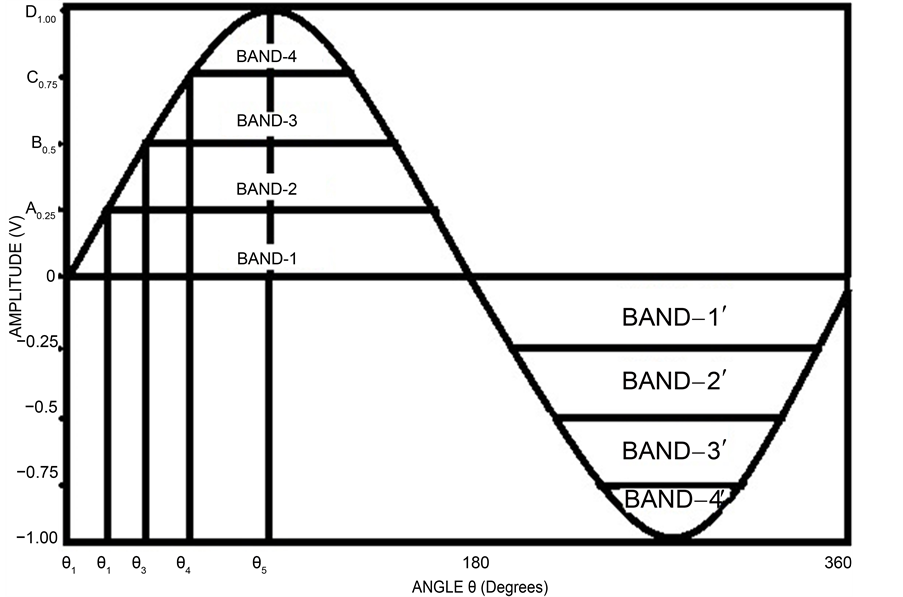 (b)
(b)
Figure 3. (a) Optimum frequency calculation for variable frequency PWM technique; (b) Reference modulating wave―four bands for different carrier frequency.

Figure 4. Carrier and reference waveforms of VF-ISPWM.
4. Simulation Result
In our proposed method, the strategy spotlighted on Phase Disposition (PD) based inverted sine PWM (ISPWM) for nine-level inverter. The parameters chosen for simulation using the proposed PWM technique is as shown in Table 2. Thus the proposed VF-ISPWM technique is proved the minimized THD and Switch utilization is significantly reduces 32.35% of the CF-ISPWM switching technique as depicted in Table 3. The comparative analysis over conventional PWM techniques is shown in Table 4.
From the Table 3 and Table 4 it is observed that variable frequency inverted sine PWM has a better spectral quality when compare to other PWM methods. The hybrid cascaded inverter is simulated for different modulation index and carrier frequency values using MATLAB/SIMULINK. Figure 5 show the load current waveform. Figure 6 shows the load current spectrum. Figure 7 shows the load voltage waveform and Figure 8 shows the load voltage spectrum of proposed methods for ma = 0.9 and Vdc = 300 V. As we shown, the proposed VFISPWM technique always claims lower THD than CFISPWM technique and the Load voltage waveform shows that the top and bottom levels of VFISPWM technique has less number of switching compared to the CF-ISPWM technique.
Figure 9 details the comparison of THD (%) vs. Modulation Index (ma) graphically. These results show that the VFISPWM method gives harmonic reduction for individual harmonic. Hence, the VF-ISPWM scheme is more favorable than the CF-ISPWM technique for hybrid asymmetric multilevel inverter.
From the above results, it is also observed that VFISPWM gives an enhanced fundamental voltage and reduced total harmonic distortion. To verify the robustness of the proposed scheme, a simulation model for a single phase hybrid cascaded MLI with Induction motor load is implemented. The motor specifications are revealed in Table 5. To prove the performance of the single phase asymmetric MLI with motor load simulation is experimented using SIMULINK block set is as shown in Figure 10 and the simulation results are verified. Figure 11 shows the stator current of 1ϕ induction motor.
The rotor speed for 1ϕ induction motor is shown in Figure 12. From the observation the rotor speed is always less than synchronous speed, so this machine is called as Asynchronous machine. The stator winding is wound for certain definite number of poles which is excited by a single phase a.c. supply so that stator produces the magnetic field which creates the effect of number of poles for which stator winding is wound, its decides the synchronous speed of the motor. The synchronous speed is denoted as Ns. The relation is given by [21] ,

 (a) (b)
Figure 5. Simulated load current waveforms. (a) VF-ISPWM; (b) CF-ISPWM.

 (a) (b)
Figure 6. Output load current spectrum. (a) VF-ISPWM; (b) CF-ISPWM.
 (a)
(a) (b)
(b)
Figure 7. Load voltage waveforms. (a) VF-ISPWM; (b) CF-ISPWM.

 (a) (b)
Figure 8. Output load voltage spectrum. (a) VF-ISPWM; (b) CF-ISPWM.

Figure 9. Variation of THD with modulation index for Constant Frequency (CF) and Variable Frequency (VF) ISPWM.
Table 2. Parameter specifications.
Table 3. Switching actions for the PWM techniques.
Table 4. Comparative analysis over conventional PWM techniques.

Figure 10. Simulation circuit for 1ϕ asymmetric hybrid cascaded MLI with induction motor.

Figure 11. Stator current for 1ϕ induction motor.
Table 5. Motor specifications.

Figure 12. Rotor speed for 1ϕ induction motor.

where Ns = synchronous speed [rpm]; f = frequency of the source [Hz]; p = number of poles. The rotor turn at slightly less than synchronous speed and the full-load slip is typically 3 percent to 5 percent for fractional horsepower motors [22] .
The electromagnetic torque and the stator flux for a 1ϕ induction motor are shown in Figure 13. The starting torque can be increased in induction motor by increasing the rotor resistance. Torque is the turning or twisting force through a radius and the units is rated in Nm. The torque developed by asynchronous induction motors varies with the speed of the motor when accelerates from zero speed to maximum operating speed. A high starting torque is more significant for application where hard to start such as positive displacement pumps, cranes. A lower starting torque can be established in applications such as centrifugal fans or a pump where the start loads is close to zero or low. The pull-up torque is the minimum torque residential by the electrical motor when it runs from zero speed to full load speed. Breakdown torque is the highest torque existing before the torque decreases when the machine continues to accelerate to the working conditions [23] .
From the speed and torque curves, it is seen that rated speed quickly achieved within 0.2 ms and the torque is quickly settled at 0.25 ms. Therefore the proposed hybrid multilevel inverter can be used for variable speed drive applications which can be obtained by varying the frequency of multilevel inverter. The harmonics in induction motor sometimes exhibit to run stably as low as 1/7 of the synchronous speed. This could be avoided by reducing the harmonics which are shown in Figure 14 and Figure 15. The total harmonic distortion is a measure of proximity in shape between a waveform and its fundamental component, the expression for THD is [8] [24] .

where (V0)n is the rms value of harmonic component and (V0)1 is the rms value of fundamental component.
The number of possible output voltage levels is twice the number of dc sources so the complexity in the cir-

Figure 13. Electromagnetic torque and stator flux for 1ϕ induction motor.

 (a) (b)
Figure 14. (a) FFT analysis of load current for VFISPWM; (b) FFT analysis of load voltage for VFISPWM.

Figure 15. THD of phase voltage for different ISPWM methods.
cuits for higher order levels with high power loads can be reduced and the series of H-bridge makes for modularized layout and packaging. This will make the manufacturing process to be done in quickly and cheaply. This structure is favorable for high power application since its produces higher voltage at higher modulation frequencies with low switching frequency. The multilevel inverter can be implementing for Hybrid Electric Vehicles (HEV) and Electric Vehicles (EV). The HEV combines a conventional IC engine, battery pack and an electric motor whereas the EV includes rechargeable batteries and an electric motor. The multilevel inverter that drives the electric motor is an input device for HEV and EV [25] [26] .
Moreover, the performance parameters measured for evaluating the proposed modulation strategy are: Crest factor, Distortion factor, WTHD and HSF.
4.1. Crest Factor (CF)
Crest factor is a measure of a waveform, such as alternating current or sound, showing the ratio of peak value to average value. Crest factor value 1 indicates no peaks, but higher crest factors indicate peaks.

where, Vpeak is the Peak Voltage and Vrms is the R.M.S Voltage.
4.2. Distortion Factor (DF)
The distortion factor is the result from a mathematical equation which resembles the geometrical means. The intensity of the nonlinear distortions is measured.

where, V1 is the Fundamental voltage, Vn is the total harmonics voltage and n is the order of the harmonics.
4.3. Weighted THD (WTHD)
The weighted total harmonic distortion (WTHD) is a commonly used to evaluate the quality of pulse width modulation (PWM) inverter waveforms. The WTHD weights the voltage harmonics is inversely with its frequency. Whereas this is tolerable for some inductor type loads, the commonly employed induction motor load has significant effects resulting from eddy currents in the rotor bars not included in the WTHD [11] .

4.4. Harmonic Spread Factor (HSF)
Harmonic Spread Factor is the deciding factor to indicate noise generation in the motor. The harmonic spread factor is calculated for evaluating the quality of voltage spectrum of inverters.

where, Hj is the value of jth harmonic and H0 is the average value of all N Harmonics.
From Table 6, it is found that the proposed modulation technique normalizes reduced THD, WTHD and distortion factor.
Moreover, with variable frequency, enhanced fundamental output is obtained. It has to be emphasized that less torque ripple for variable frequency PWM technique leads to better stability operation with minimum mechanical noise.
Table 6. Performance parameter of hybrid MLI.
5. Experimental Result
To validate the single-phase asymmetric hybrid cascaded H-bridge multilevel inverter, a prototype module is built using CT60AM18F smart power module (SPM) as the switching devices and is experimented as shown in Figure 16. SPARTAN-3E FPGA processor is used to implement the gating pattern that associates and evaluates with other modules, hybrid MLI setup (optocoupler, driver & power circuit) and load configuration.
The inverter was first controlled by using constant frequency ISPWM with the following parameters: ma = 0.9 and mf = 79. The prototype inverter was tested using the proposed VFISPWM with different carrier frequencies which balances the switching actions and gives a lower value of THD compared to the CFISPWM. Hardware set-up for Single phase power circuit with optocoupler is exposed in Figure 16(a) and the experimental setup for the asymmetric MLI is shown in Figure 16(b).
The specifications for semiconductor device are: Part Number: CT60AM-18F, Voltage rating = 900 V and Current rating = 60 A. Figure 17 shows the block diagram of proposed system.
PWM generators incorporated within microcontrollers are not normally flexible enough to generate switching pulse, so that Field Programmable Gate Array (FPGA) based controller is employed. The pulse produced by FPGA processor is transmitted through an optocoupler to the multilevel inverter. The core processor of the system is a Xilinx FPGA, Spartan 3E programmed through a Xilinx EEPROM. The FPGA program is downloaded from Personal Computer through a parallel cable to the EEPROM using master serial mode and the stored program in the electrically erasable programmable ROM (EEPROM) is reloaded to the FPGA once it is reset [27] . Figure 18 shows the load voltage and load current waveform.
The proposed strategy is employed for single phase RL load which have the value of R = 10 ohms and L = 0.024 mH. The inductance value is small, so that the load voltage and load current waveforms are identical. The simulation is carried out for the motor load in order to calculate the performance of the MLI with Variable frequency ISPWM. This will be helpful to design the hardware for induction motor load.
From the above Table 7, it is seen that variable frequency ISPWM reduces the harmonics for both simulation and experimental work when compare to constant frequency inverted sine PWM. Figure 19 shows experimental results with power quality analyzer. The variable frequency inverted sine PWM gives reduced harmonics as VTHD = 4.45% & ITHD = 5.95% where as constant frequency inverted sine PWM gives VTHD = 6.28% & ITHD = 6.25%.
Insulated Gate Bipolar Transistor (IGBT) is a very popular device among power semiconductor due to its easy switching and handles high level of power demand by Hybrid Electric Vehicles (HEV) motor drives. In this work, Cascaded H-Bridge Multilevel Inverter can be interfaced with electric drives of HEVs because of following features.
1) When compare to diode clamped and flying capacitor MLI, the number of components is less.
2) It is suitable for high current and low voltage rating electric drives which are needed for Hybrid Electric Vehicles.
3) Cascaded H-Bridge Multilevel Inverter can be switched at low frequency, so that noise can be suppressed which is comfortable for driving HEVs [25] .
The three single-phase multilevel inverter are connected in parallel to add up the voltage. The output of the three single phase inverter needs to be synchronized with separation of 120 degree between each phase. So that we can implement for three phase circuit.
 (a)
(a)
 (b) (c)
Figure 16. (a) Hardware setup; (b) Experimental setup; (c) CRO nine-level output.

Figure 17. Block diagram of the proposed system.

Figure 18. Experimental load voltage and load current waveforms.
 (a)
(a) (b)
(b)
Figure 19. THD values of load voltage and load current measured using PQ analyzer. (a) VF-ISPWM; (b) CF-ISPWM.
Table 7. Validation of experimental and simulated results.
6. Conclusion
Thus the simulation and experimental results demonstrated the ability of the proposed methodology to effectively be used to increase the performances of the MLIs. A comparative evaluation between CFISPWM & VFISPWM methods has been presented in terms of output voltage quality, power circuitry complexity and THD. From this observation VFISPWM technique provides an enhanced fundamental voltage and reduced THD compared to other conventional strategies. To overcome the marginal boost in the magnitude of lower order harmonics and unbalanced switch utilization, variable frequency inverted sine carrier signals are employed. Now, it is proved that the VFISPWM method gives a better performance and THD for a chosen modulation index. Further, the proposed MLI with reduced number of switches can also be employed for electric vehicle applications.
Cite this paper
M. Sudhakaran,R. Seyezhai, (2016) Modeling and Analysis of Variable Frequency Inverted Sine PWM Technique for a Hybrid Cascaded Multilevel Inverter. Circuits and Systems,07,2633-2650. doi: 10.4236/cs.2016.79228
References
- 1. Lai, J.S. and Peng, F.Z. (1996) Multilevel Converters—A New Breed of Power Converters. IEEE Transactions on Industrial Applications, 32, 509-517.
http://dx.doi.org/10.1109/28.502161 - 2. Song, Y. and Wang, B. (2013) Survey on Reliability of Power Electronic Systems. IEEE Transactions on Power Electron, 28, 591-604.
http://dx.doi.org/10.1109/TPEL.2012.2192503 - 3. Azli, N.A. and Choong, Y.C. (2006) Analysis on the Performance of a Three Phase Cascaded H Bridge Multilevel Inverter. 2006 IEEE International Power and Energy Conference, Putrajaya, Malaysia, 28-29 November 2006, 405-410.
http://dx.doi.org/10.1109/PECON.2006.346685 - 4. Hosseini Aghdam, M.G., Fathi, S.H. and Gharehpetian, B. (2008) A Novel Carrier Based PWM Method for THD Reduction in Asymmetric Multilevel Inverter. Proceeding of the International Conference on Renewable Energies and Power Quality, Spain, 12-14 March 2008, 105-110.
- 5. Rodr1guez, J., Lai, J. and Peng, F. (2002) Multilevel Inverters: A Survey of Topologies, Controls and Applications. IEEE Transactions on Industrial Electron, 49, 724-738.
http://dx.doi.org/10.1109/TIE.2002.801052 - 6. Lai, Y.S., Lin, Y.K. and Chen, C.W. (2013) New Hybrid Pulse width Modulation Technique to Reduce Current Distortion and Extend Current Reconstruction Range for a Three-Phase Inverter Using Only DC-Link Sensor. IEEE Transactions on Power Electron, 28, 1331-1337.
http://dx.doi.org/10.1109/TPEL.2012.2207406 - 7. Babaei, E. (2008) A Cascade Multilevel Converter Topology with Reduced Number of Switches. IEEE Transactions on Power Electron, 23, 2657-2664.
http://dx.doi.org/10.1109/TPEL.2008.2005192 - 8. Urmila, B. and Rohit, R. (2012) Performance Evaluation of Multilevel Inverter Based on Total Harmonic Distortion (THD). International Journal of Engineering Science & Advanced Technology, 2, 587-593.
- 9. Hosseini Aghdam, M.G. and Fathi, S.H. (2005) Modeling of Conduction and Switching Losses in Three Phase Asymmetric Multilevel Cascaded Inverter. Proceedings of the 5th WSEAS International Conference on Power Systems and Electromagnetic Compatibility, Corfu, 23-25 August 2005, 176-181.
- 10. Jeevananthan, S., Nandhakuma, R. and Perumal, D. (2007) Inverted Sine Carrier for Fundamental Fortification in PWM Inverters and FPGA Based Implementations. Serbian Journal of Electrical Engineering, 4, 171-187.
http://dx.doi.org/10.2298/SJEE0702171J - 11. Lipo, T.A. (2000) An Improved Weighted Total Harmonic Distortion Index for Induction Motor Drives. OPTIM, Brasov, Romania, 2, 311-322.
- 12. Magdun, O. and Binder, A. (2012) The High-Frequency Induction Machine Parameters and Their Influence on the Common Mode Stator Ground Current. 2012 XXth International Conference on Electrical Machines (ICEM), Marseille, 2-5 September 2012, 505-511.
http://dx.doi.org/10.1109/ICElMach.2012.6349917 - 13. Seyezhai, R. and Mathur, B.L. (2010) Implementation and Control of Variable Frequency ISPWM Method for an Asymmetric Multilevel Inverter. European Journal of Scientific Research, 39, 558-568.
- 14. Zhong, D., Tolbert, L.M., Ozpineci, B. and Chiasson, J.N. (2009) Fundamental Frequency Switching Strategies of a Seven-Level Hybrid Cascaded H-Bridge Multilevel Inverter. IEEE Transactions on Power Electronics, 24, 25-23.
http://dx.doi.org/10.1109/TPEL.2008.2006678 - 15. Hosseini Aghdam, M.G., Fathi, S.H. and Gharehpetian, B. (2008) Analysis of Multi-Carrier PWM Methods for Asymmetric Multilevel Inverter. 2008 3rd IEEE Conference on Industrial Electronics and Applications, Singapore, 3-5 June 2008, 2057-2062.
http://dx.doi.org/10.1109/ICIEA.2008.4582882 - 16. Liu, H., Tolbert, L.M., Ozpineci, B. and Du, Z. (2008) Comparison of Fundamental Frequency and PWM Methods Applied on a Hybrid Cascaded Multilevel Inverter. IEEE Industrial Electronics Society Annual Conference, Orlando, 10-13 November 2008, 3233-3237.
- 17. Radan, A., Shahirinia, A.H. and Falahi, M. (2007) Evaluation of Carrier—Based PWM Methods for Multi-Level Inverters. Proceedings of IEEE International Symposium on Industrial Electronics (ISIE), Vigo, 4-7 June 2007, 389- 394.
- 18. Seyezhai, R. and Mathur, B.L. (2009) Performance Evaluation of Inverted Sine PWM Techniques for an Asymmetric Multilevel Inverter. Journal of Theoretical and Applied Information Technology, 2, 91-98.
- 19. Seyezhai, R. and Mathur B.L. (2008) Harmonic Evaluation of Multi-Carrier PWM Techniques for Cascaded Multilevel Inverter. Proceedings of 2nd International Conference on Electrical Engineering and Its Applications (ICEEA), Algeria, 20-21 May 2008, 3-8.
- 20. McGrath, B.P. and Grahame Holmes, D. (2002) Sinusoidal PWM of Multilevel Inverters in the Over Modulation Region. 2002 IEEE 33rd Annual of Power Electronics Specialists Conference, 2, 485-490.
http://dx.doi.org/10.1109/PSEC.2002.1022500 - 21. Song Manguelle, J. (2001) Asymmetrical Multilevel Inverter for Large Induction Machine Drive. Electrical Drives and Power Electronics International Conference, Slovakia, 3-5 October 2001, 101- 107.
- 22. Toliyat, H.A., Nandi, S., Choi, S. and Kelk, H.M. (2013) Electric Machines—Modeling, Condition Monitoring and Fault Diagnosis. Taylor and Francis Group, Power and Energy Series, CRC Press, Boca Raton, 56.
- 23. Gyftakis, K.N., Spyropoulos, D.V., Kappatou, J. and Mitronikas, E.D. (2013) A Novel Approach for Broken Bar Fault Diagnosis in Induction Motors through Torque Monitoring. IEEE Transaction on Energy Conservation, 28, 267-277.
http://dx.doi.org/10.1109/TEC.2013.2240683 - 24. Chaturvedi, P.K., Jain, S., Agrawal, P., Nema, R.K. and Sao, K.K. (2008) Switching Losses and Harmonic Investigations in Multilevel Inverters. IETE Journal of Research, 54, 297-307.
http://dx.doi.org/10.4103/0377-2063.44233 - 25. Tabbache, B., Benbouzid, M., Kheloui, A., Bourgeot, J.-M. and Mamoune, A. (2013) PWM Inverter-Fed Induction Motor-Based Electrical Vehicles Fault-Tolerant Control. IEEE Transactions on Power Electron, Vienna, 10-13 November 2013, 8204-8209.
http://dx.doi.org/10.1109/iecon.2013.6700506 - 26. Rodriguez, J., Bernet, S., Wu, B., Pontt, J.O. and Kouro, S. (2007) Multilevel Voltage Source Converter Topologies for Industrial Medium-Voltage Drives. IEEE Transactions on Industrial Electron, 54, 2930-2945.
http://dx.doi.org/10.1109/TIE.2007.907044 - 27. Valantina, S., Padma, S.L. and Muthukumar, P. (2012) Field Programmable Gate Array Based RF-THI Pulse Width Modulation Control for Three Phase Inverter Using Matlab Modelsim Cosimulation. American Journal of Applied Sciences, 9, 1802-1812.
http://dx.doi.org/10.3844/ajassp.2012.1802.1812