Paper Menu >>
Journal Menu >>
 Journal of Software Engineering and Applications, 2011, 4, 217-226 doi:10.4236/jsea.2011.44024 Published Online April 2011 (http://www.SciRP.org/journal/jsea) Copyright © 2011 SciRes. JSEA 217 Towards a Model-Driven IEC 61131-Based Development Process in Industrial Automation* Kleanthis Thramboulidis1,2, Georg Frey2 1Electrical and Computer Engineering, University of Patras, Patras, Greece; 2Saarland University, Saarbrucken, Germany. Email: thrambo@ece.upatras.gr, kleanthis.thramboulidis@mx.uni-saarland.de, georg.frey@aut.uni-saarland.de Received March 14th, 2011; revised March 24th, 2011; accepted March 27th, 2011. ABSTRACT The IEC 61131-3 standard defines a model and a set of programming languages for the development of industrial au- tomation softwa re. It is widely accep ted by indu stry and most of the commercia l tool vendo rs advertise comp liance with it. On the other side, Model Driven Development (MDD) has been proved as a quite successful paradigm in gener- al-purpose computing . This was the motivation for exploiting th e benefits of MDD in the industrial automa tion domain. With the emerging IEC 61131 specifica tion that defines an object-orien ted (OO) extension to the function block model, there will be a push to the industry to better exploit the benefits of MDD in automation systems development. This work discusses possible alternatives to integrate the current but also the emerging specification of IEC 61131 in the model driven development process of automation systems. IEC 61499, UML and SysML are considered as possible alterna- tives to allow the developer to work in higher layers of abstraction than the one supported by IEC 61131 and to more effectively move from requirement specifications into the implementation model of the system. Keywords: In d ustri al Aut o m a t i on Systems, Model Driven Development, IEC 61131, System Modeling, UML, SysML, IEC 61499, Development Process 1. Introduction The IEC 61131-3 standard [1] has been adopted by the industry and is widely used by control engineers in speci- fying the software part of systems in the industrial auto- mation domain. However, it imposes several restrictions for the development of today’s complex systems. There is a trend to exploit best practices from the desktop applica- tion domain. Object orientation, component based deve- lopment and model driven engineering are among these widely accepted best practices. Several research groups are already working to this direction, e.g., [2-5]. Standar- dization is also following this trend. The IEC 61499 stan- dard [6] is considered as an extension of IEC 61131, to address among others object oriented (OO) concepts and the IEC 61131 working group is currently discussing an Object-Oriented extension to the standard [7]. Model Driven Development (MDD) was widely ac- cepted as a successful paradigm in the desktop domain. The key issue in MDD is that models have become pri- mary artifacts of software design, shifting much of the focus away from program code. Thus MDD refers to “a set of approaches in which code is automatically or semi automatically generated from more abstract models, and which employs standard specification languages for de- scribing those models and the transformations between them” [8]. According to this definition the use of the Function Block Diagram (FBD) graphical programming language of IEC 611131-3 in the specification of the design model of the controller’s software and its subsequent automatic translation to executable code for the target PLC platform, characterizes the development process as model driven, at least partially. Moreover, existing tools provide support for code generation for several execution platforms. This leads to the following question: what is all this research about defining MDD approaches based on IEC 61131-3 and 61499, in the industrial automation domain? The drawback of the IEC 61131 FBD is that it provi- des only one kind of diagram that can be used to constru- ct the model of the application software. This diagram is composed of FB instances and their interconnections. A similar diagram is also found in IEC 61499. In this paper, we refer to this diagram with the term Function Block *The authors would like to thank Stifterverband für die Deutsche Wis- senschaft and ME Saar for partially funding this project.  Towards a Model-Driven IEC 61131-Based Development Process in Industrial Automation Copyright © 2011 SciRes. JSEA 218 Network (FBN). The FBN is used in the FBD language to model the structure and the behavior of Programs or FBs. Taking into consideration now that the Unified Mo- deling Language (UML) and the Systems Modeling Lan- guage (SysML) use several diagrams for the definition of the application’s structure and behavior, it is clear that the one diagram used by IEC 61131 is not enough to cons- truct a reliable and expressive model for the application software. This means that all discussion about an MDD approach based on 61131 has to do with the use of more diagrams to allow: 1) more abstract models to be constructed, and 2) more aspects of the system to be captured in order to have a more complete and comprehensible model of the system. In this paper, IEC 61499, UML and SysML are consi- dered as candidate notations to address this challenge. In a first step the IEC 61131 FBD notation is analyzed from the viewpoint of the object oriented paradigm. This is a prerequisite in order to have a sound and clear understan- ding of the OO concepts supported by the 61131 FBD notation. It will also simplify the process of mapping this notation to the three other notations that are examined in this paper. Instead of what is widely believed, IEC 61131 has already introduced in the industrial automation do- main, at least at the specification level, basic concepts of the OO paradigm. The Festo MPS laboratory system, a well documented system used by many universities for research and educa- tion purposes, is used as a running example in this paper. It is composed of three units. The Distribution unit, which is composed of a pneumatic feeder and a converter, for- wards cylindrical work pieces from a Stack to the Testing unit. The Testing unit performs checks on work pieces for height, material type and color. Work pieces that suc- cessfully pass this check are forwarded to the rotating disk of the Processing unit, where the drilling of the work piece is performed as the primary processing of this sys- tem. The result of the drilling operation is next checked by the checking machine and the work piece is forwarded for further processing to another mechanical unit. A de- tailed description of the system, as well as a design of the control application based on the IEC 61499 can be found in [9]. The remainder of this paper is organized as follows: Section 2, presents the related work on using UML and SysML. In section 3, the IEC 61131 FBD notation is exa- mined in detail from the object oriented viewpoint. The focus is on structure and behavior definition of Function Block type and Function Block network. In Section 4, we consider the potentials of using IEC 61499, UML and SysML towards a more effective MDD process based on the IEC 61131 FBD notation. The paper is concluded in the last section. 2. Related Work There are already several works that try to integrate IEC 61131 with UML and SysML. Vogel-Heuser, et al. in [10] describe the automatic generation of IEC 61131 code ex- pressed in Structured Text (ST) and Sequential Function Chart (SFC) from UML 1.4 diagrams. Class diagrams are used to capture the structure of the application, while state charts are considered similar to SFCs and they are used to capture the behavior. The authors do not map the UML class to FB directly but instead they propose a complex implementation of the class concept using nested FBs. Furthermore, the object oriented view of the FB construct is not exploited and the FB diagram is considered as a diagram to capture behavior. Ramos et al., in [11] describe an OO environment they have developed for the development and implementation of distributed process control systems. This environment is based on the integration of UML with IEC 61131 and Simulink. They use class diagrams and statechart diagra- ms to create the requirements model of the application and they implement a mapping of SFC to UML state- charts. In fact they use UML as an intermediate model in their transformation from Simulink and IEC 61131 to Java code. Sacha in [12] describes an approach that allows the de- veloper to model the behavior using UML state charts which are verified using UPPAAL, a model checking tool for timed automata. These state charts are then automati- cally transformed to an IEC 61131 program for STEP 7. This work does not give any focus on the structural aspe- cts of the application and does not use scenario and ac- tivity diagrams that provide a more effective modeling process for the behavior, when used in combination with state charts. A UML specialization for process automation (UML-PA) is presented by Katzke, et al., in [13]. The authors pro- pose the use of only six UML diagrams for the modeling of the system and the use of IEC 61131 languages to de- scribe the actions in UML state charts. However, a speci- fic mapping between these six UML diagrams and the corresponding IEC 61131 code is not given. SysML is evaluated in [14] by Chiron et al., as a mod- eling notation for programmable logical controllers. Even though the authors propose the use of block definition diagram (bdd) of SysML to represent structure, they con- sider the internal block diagram (ibd) of SysML as the proper diagram to represent the IEC 61131 FBN. They use atomic flow ports to represent the interconnection points of the FB with the environment, and the activity diagram to represent the behavior. In the decomposition process of the program they use the term task and this is 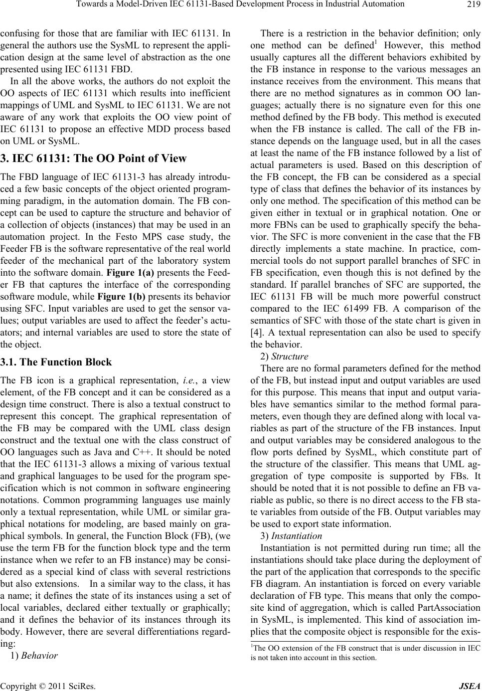 Towards a Model-Driven IEC 61131-Based Development Process in Industrial Automation Copyright © 2011 SciRes. JSEA 219 confusing for those that are familiar with IEC 61131. In general the authors use the SysML to represent the appli- cation design at the same level of abstraction as the one presented using IEC 61131 FBD. In all the above works, the authors do not exploit the OO aspects of IEC 61131 which results into inefficient mappings of UML and SysML to IEC 61131. We are not aware of any work that exploits the OO view point of IEC 61131 to propose an effective MDD process based on UML or SysML. 3. IEC 61131: The OO Point of View The FBD language of IEC 61131-3 has already introdu- ced a few basic concepts of the object oriented program- ming paradigm, in the automation domain. The FB con- cept can be used to capture the structure and behavior of a collection of objects (instances) that may be used in an automation project. In the Festo MPS case study, the Feeder FB is the software representative of the real world feeder of the mechanical part of the laboratory system into the software domain. Figure 1(a) presents the Feed- er FB that captures the interface of the corresponding software module, while Figure 1(b) presents its behavior using SFC. Input variables are used to get the sensor va- lues; output variables are used to affect the feeder’s actu- ators; and internal variables are used to store the state of the object. 3.1. The Function Block The FB icon is a graphical representation, i.e., a view element, of the FB concept and it can be considered as a design time construct. There is also a textual construct to represent this concept. The graphical representation of the FB may be compared with the UML class design construct and the textual one with the class construct of OO languages such as Java and C++. It should be noted that the IEC 61131-3 allows a mixing of various textual and graphical languages to be used for the program spe- cification which is not common in software engineering notations. Common programming languages use mainly only a textual representation, while UML or similar gra- phical notations for modeling, are based mainly on gra- phical symbols. In general, the Function Block (FB), (we use the term FB for the function block type and the term instance when we refer to an FB instance) may be consi- dered as a special kind of class with several restrictions but also extensions. In a similar way to the class, it has a name; it defines the state of its instances using a set of local variables, declared either textually or graphically; and it defines the behavior of its instances through its body. However, there are several differentiations regard- ing: 1) Behavior There is a restriction in the behavior definition; only one method can be defined1 However, this method usually captures all the different behaviors exhibited by the FB instance in response to the various messages an instance receives from the environment. This means that there are no method signatures as in common OO lan- guages; actually there is no signature even for this one method defined by the FB body. This method is executed when the FB instance is called. The call of the FB in- stance depends on the language used, but in all the cases at least the name of the FB instance followed by a list of actual parameters is used. Based on this description of the FB concept, the FB can be considered as a special type of class that defines the behavior of its instances by only one method. The specification of this method can be given either in textual or in graphical notation. One or more FBNs can be used to graphically specify the beha- vior. The SFC is more convenient in the case that the FB directly implements a state machine. In practice, com- mercial tools do not support parallel branches of SFC in FB specification, even though this is not defined by the standard. If parallel branches of SFC are supported, the IEC 61131 FB will be much more powerful construct compared to the IEC 61499 FB. A comparison of the semantics of SFC with those of the state chart is given in [4]. A textual representation can also be used to specify the behavior. 2) Structure There are no formal parameters defined for the method of the FB, but instead input and output variables are used for this purpose. This means that input and output varia- bles have semantics similar to the method formal para- meters, even though they are defined along with local va- riables as part of the structure of the FB instances. Input and output variables may be considered analogous to the flow ports defined by SysML, which constitute part of the structure of the classifier. This means that UML ag- gregation of type composite is supported by FBs. It should be noted that it is not possible to define an FB va- riable as public, so there is no direct access to the FB sta- te variables from outside of the FB. Output variables may be used to export state information. 3) Instantiation Instantiation is not permitted during run time; all the instantiations should take place during the deployment of the part of the application that corresponds to the specific FB diagram. An instantiation is forced on every variable declaration of FB type. This means that only the compo- site kind of aggregation, which is called PartAssociation in SysML, is implemented. This kind of association im- plies that the composite object is responsible for the exis- 1The OO extension of the FB construct that is under discussion in IEC is not taken into account in this section.  Towards a Model-Driven IEC 61131-Based Development Process in Industrial Automation Copyright © 2011 SciRes. JSEA 220 (a) (b) Figure 1. IEC 61131 FB for the Festo MPS feeder: (a) interface, (b) behavior specification using SFC.  Towards a Model-Driven IEC 61131-Based Development Process in Industrial Automation Copyright © 2011 SciRes. JSEA 221 tence and storage of the composed objects, i.e., its parts. 4) Inheritance Inheritance between FB types is not supported. 5) Interface Interface definition is not supported. 3.2. The Function Block Network The FBN is a design time artifact. Even though the FBN can be considered as a structural specification diagram like the composite structure diagram of UML 2.0 or the internal block diagram (ibd) of SysML, it is actually used, according to the standard, to capture the behavior of Pro- grams and FBs. The closest UML diagrams that can be compared with the FBN are the activity and collaboration diagrams. However, the execution semantics of the FBN, and more specifically those related to the execution order and flow of control are quite different from the ones of the above diagrams. Moreover, the level of abstraction applied in FBN is lower compared to the level of abstrac- tion of the UML diagrams. In the activity and collabora- tion diagrams of UML, the execution order and flow of control may be captured on the diagrams and explicitly specified by the designer. On the other hand, there are predefined execution semantics in FBN, such as the order of calling functions or FB instances. It is the responsibil- ity of the designer to ensure that the proposed design ex- ploits properly the predefined execution semantics in or- der to get the desired behavior. The FBN is analogous to the abstract syntax tree generated by a C compiler to cal- culate the value of an expression. Like the Activity dia- gram, the FBN diagram captures the activities that have to be performed and the flow of information between these activities. An FBN that includes only FB instances is more close to a collaboration diagram with the restric- tion that every object has one method. Message passing between the nodes of an FBN is not realized in terms of method call that is the common me- chanism for message passing in OO languages. In fact, there are no method signatures, but just one FB method which is activated when the FB instance is called. An FB instance can be called by any Program Organization Unit (POU) that has visibility access to it. The FB method is executed on the specific instances structure, i.e., inputs, state and output. The result is normally: 1) a new instan- ce state that is captured in the instance’s internal varia- bles, in the case of state depended behavior, and 2) a res- ponse to the environment that is captured by the instan- ce’s output variables and the value of the FB call. Messa- ge passing between FB instances allocated in different resources in the same configuration is implemented by global variables (VAR_GLOBAL) of the configuration, while between those allocated in different configurations is implemented through access paths defined in configu- rations with VAR_ACCESS. 4. Towards a More Effective Modeling Process for IEC 61131 4.1. The Need for More Diagrams and for Higher Levels of Abstraction in Application Modeling As it was stated above, the IEC 61131-3 FBD language can be considered as a realization of the MDD paradigm in the industrial automation domain. However, it can be used to model the application to a very low level of abs- traction, very close to the executable code. It does not al- low the designer to capture in a graphical way all the aspects of the application, as for example its structure. Moreover, even though the execution semantics are well defined and common for all the IEC 61131-3 compliant execution environments, it is more informative for the control engineer to have a graphical representation of this information using sequence or activity diagrams. In this case, these diagrams may be used even before the assign- ment of the application activities to function blocks, al- lowing a more flexible transition from the system re- quirements to the application design specifications. In order to increase the effectiveness of this MDD pro- cess, more models should be exploited, e.g., to capture the behavior, and also new ones more abstract should be used, e.g., to support the definition of the structure of the application. These models, if properly defined, would be automatically transformed to the IEC 61131 FBD nota- tion and finally to executable code for existing run-time environments. In this section, three notations are consi- dered as possible candidates for such an extension of the IEC 61131-based modeling process: 1) the IEC 61499 function block model, 2) the UML, and 3) the systems modeling language SysML. Moreover, it should be noted that the device centric approach, which is currently used with the IEC 61131, does not provide a strong request for higher layers of ab- straction in the development process. However, this ap- proach does not allow for the adoption of a synergistic development process of the constituent parts of the au- tomation system that is the current trend in Metchatronic systems development [15], such as the industrial automa- tion systems. The application centric paradigm, that is proposed to better fit with the synergistic development of the constituent parts of the automation system, is almost impossible to be applied without special emphasis on the architecture of the system. This is why UML and SysML may be used as early specifications of the automation system, during the development process, before the 61131 one. In [16] a detailed discussion, including examples, is  Towards a Model-Driven IEC 61131-Based Development Process in Industrial Automation Copyright © 2011 SciRes. JSEA 222 given on the limitations of IEC 61499 to be used as nota- tion for architectural specification. On the other hand UML and SysML are widely accepted as architecture specification languages. 4.2. Using IEC 61499 The IEC 61499 FB model has been proposed by IEC as an extension of the IEC 61131 FB one to exploit OO concepts and address several other challenges in indus- trial automation systems, such as interoperability, porta- bi-lity, run-time reconfigurability, etc. However, even though several researchers have published many articles on the applicability of the new standard, e.g. [17], and also on the migration from IEC 61131 to IEC 61449, such as Gerber et al., in [18] and Hussain et al. in [19], the industry has not yet made serious steps towards its adoption [16]. When the first proposal for the Object- Oriented extension of IEC 61131 FB model was presen- ted by CODESYS, a debate has raised between the two communities [20]. Does the industry need both standards or the new version of IEC 61131 will officially denote the abandonment of IEC 61499? Or, in other words, what is the value added of IEC 61499 compared to IEC 61131? In this subsection we assess the potential of using IEC 61499 to enhance the IEC 61131 development process. Due to our assumption to be compliant with the execu- tion semantics of IEC 61131 that includes execution of the program based on cyclic or periodic mode, the events of IEC 61499 FB, at least those that interconnect the FBN with the controlled system, are useless. Based on this, the main differences between IEC 61131 and IEC 61499 FB are: 1) The IEC 61499 uses the ECC to capture the dyna- mic behavior of its instances. However, this is nothing more than a graphical way of representing the IEC 61131 FB body that can also be done using SFC, as shown in Figure 1. 2) The ability to specify in IEC 61499 the behavior to incoming events as independent distinct algorithms (me- thods). This allows for a more modular FB body but since there is no support for inheritance there are no direct be- nefits regarding reusability. It should be noted that the restriction of IEC 61499 to disallow a direct method call bypassing the ECC is con- sidered very positive for this kind of systems. However, the introduction of the algorithm scheduling function im- poses a very heavy constraint on the Safety Integrity Le- vel that can be obtained using IEC 61499. The differences are more important when we consider the FBNs. As already mentioned the IEC 61131 FBN is used to model the behavior. The IEC 61499 FBN is quite similar to the UML composite diagram or the SysML internal block definition (ibd) diagram. It represents the structure of the application or the composite FB and all the possible interactions among them. Figure 2 presents an FBN for the distribution unit of the Festo MPS exam- ple application. As argued by Thramboulidis et al. in [21], the FBN is not considered appropriate for behavior mod- eling. This means that the IEC 61499 does not provide a better way to capture the behavior of the application compared to the IEC 61131. It is only the FBN that has to be evaluated as a possible diagram to enhance the IEC 61131 development process. But as argued in [19], the IEC 61499 is not considered as an effective architecture specification language. Based on the above analysis, the authors do not see any valuable benefit in using IEC 61499 to enhance the IEC 61131 development process. It does not provide di- agrams for higher level of abstractions models, nor even diagrams to effectively model the other aspects of the application. 4.3. Using UML It is evident that a specific UML class may be used to re- present the IEC 61131 FB. Moreover, several UML dia- grams can be used to create more abstract models of the application, compared to the one supported by the IEC 61131 FBD. More specifically: 1) The UML composite diagram can be used to cap- ture the structure of programs and FBs. 2) The state diagram can be used to capture the beha- vior of programs and FBs. 3) The sequence and/or activity diagrams may be used to model the behavior in terms of interactions between FB instances, and to model the behavior of an enclosing FB. 4) The class diagram may be used to represent the structure of the PLC infrastructure. 5) The deployment diagram may be used as graphical representation of a configuration. To have a better exploitation of the above UML dia- grams in the domain of IEC 61131, a UML profile may be defined. This profile will contain stereotypes for the main key constructs of IEC 61131. For example the spe- cific UML class that will be used to represent the IEC 61131 FB will be a stereotype of this profile. This profile will allow the industrial engineer to build the models using already known constructs and at the same time to work in the UML abstraction layer. This means that it is possible to create the model of the application in more abstract format compared to IEC 61131, while still using the IEC 61131 basic terminology. Specific model-to-model transformers are required to have an automatic transfor- mation of the UML application specification to an IEC 61131 based one, which will be subsequently translated  Towards a Model-Driven IEC 61131-Based Development Process in Industrial Automation Copyright © 2011 SciRes. JSEA 223 Figure 2. IEC 61499 function block network for the Festo MPS distribution unit. using existing tools to executable code for commercial run-time environments. The definition of the meta-models of the source and target domains, as well as the set of mapping rules between them, is a prerequisite for this ap- proach to be effectively implemented. A problem with UML is that the class concept is specifically defined to support the OO programming paradigm, so UML does not provide inherent support for the procedural paradigm that is also supported by IEC 61131. This is why SysML is considered a better choice for building a more effective higher layer of abstraction on top of IEC 61131. 4.4. Using SysML The construct of block that is the basic static, structural construct of SysML, is broader than the UML class. The block can be used to represent the modular units of sys- tem description. A block can define the “type of logical or conceptual entity, a physical entity, a hardware, soft- ware or data component, a person, a facility, an entity that flows in the system or even entities from the environ- ment” [22]. This means that the block construct of SysML may be used to represent not only an FB, but also a func- tion and a configuration. The <<FB>> stereotype will be used to represent the IEC 61131 FB and the <<Func- tion>> stereotype will be used to represent the IEC 61131 function. In a similar way <<Program>> and <<Confi- guration>> will be defined to represent a program and a configuration respectively. The SysML block definition diagram (bdd) can be used to capture the structure of configurations, programs and also FBs that may accept FB instances as input variables. Figure 3 shows the bdd for the Distribution Unit block of the Festo MPS mod- eled in SysML. It consists of a Feeder FB instance, a Converter FB instance and an FB instance of type Dis- tributionUnit, that coordinates these. The same diagram presents also the interfaces of Fee- der and Converter, as well as the flow specifications for the interactions of real world feeder and converter with the corresponding FB instances. The SysML internal blo- ck diagram (ibd) can be used to capture the interconnec- tions among the constituent parts of constructs, such as configurations, programs and also FBs that may accept FB instances as input variables. The sequence diagram can be used to capture the inter- actions of the system components in the context of a par- ticular operation of the system. The SysML sequence diagram, shown in Figure 4, captures the interaction of the system components in the context of the reaction of  Towards a Model-Driven IEC 61131-Based Development Process in Industrial Automation Copyright © 2011 SciRes. JSEA 224 Figure 3. SysML block definition diagr am (bdd) for the festo MPS distribution unit. the control application to the sensor event frontPosRea- ched that comes from the corresponding sensor of the mechanical Feeder. From SysML design diagrams as the ones shown in Figures 3 and 4, using proper model-to-model transfor- mers, we may get the corresponding IEC 61131 design diagrams for the application. In this way SysML can be used to provide a completely graphical environment for modeling control applications in a higher and also more expressive layer than the one already supported by IEC 61131 market tools. This profile can be developed from scratch or more effectively based on an existing profile in the embedded real-time systems domain, such as the MARTE profile [23]. Assuming that the corresponding profile will be standardized, this approach will result in a uniform way of modeling industrial automation software that will hide the proprietary individual characteristics of IEC 61131 tools at the modeling layer. 5. Conclusions The IEC 61131-3 standard has already introduced in the industrial automation domain basic concepts of the OO paradigm, even though these are not widely exploited in practice by existing development tools. It has also intro- duced the use of graphical notations, i.e., the use of mod- els, in the development process. The FBD language is an attempt to use graphical models in the development pro- cess that is one of the basics of model driven develop- ment paradigm. However, the FBD notation does not support modeling at high levels of abstraction, that is required when the size and complexity of the application is increasing. Moreover, it does not allow the modeling of all aspects of the application. We have discussed, in this paper, three notations as candidates to address the increasing size and complexity of industrial applications. IEC 61499, UML and SysML were examined for possible integration with IEC 61131 to increase the effectiveness of the IEC 61131-based de- velopment processes. IEC 61499 does not provide any valuable benefit in enhancing the IEC 61131 development process. UML may be successfully used, but SysML seems to better match the semantics of IEC 61131. With a proper profile, SysML can be used to define a comple- tely graphical environment that will allow the industrial automation developer to create the model of the applica- tion and automatically transform it to IEC 61131 speci- fication. This integration may also hide the proprietary individual characteristics of IEC 61131 market tools at  Towards a Model-Driven IEC 61131-Based Development Process in Industrial Automation Copyright © 2011 SciRes. JSEA 225 Figure 4. SysML Collaboration diagram for the reaction of the Feeder unit to the frontPos- Reached signal of the corresponding Feeder sensor. the modeling layer and result in a uniform modeling no- tation. REFERENCES [1] International Electrotechnical Commission, “IEC Interna- tional Standard IEC 61131-3: Programmable Controllers, Part 3: Programming Languages,” IEC, 2003. [2] G. Doukas and K. Thramboulidis, “A Real-Time Linux Based Framework for Model-Driven Engineering in Con- trol and Automation,” IEEE Transactions on Industrial Electronics, Vol. 58, No. 3, March 2011, pp. 914-924. [3] D. Streitferdt, G. Wendt, P. Nenninger, A. Nyssen and H. Lichter, “Model Driven Development Challenges in the Automation Domain,” 32nd Annual IEEE International Conference on Computer Software and Applications, Turku, 28 July-1 August 2008, pp. 1372-1375. [4] S. Panjaitan and G. Frey, “Combination of UML Model- ing and the IEC 61499 Function Block Concept for the development of Distributed Automation Systems,” 11th IEEE International Conference on Emerging Technolo- gies and Factory Automation, Prague, September 2006, pp. 766-773. [5] K. Thramboulidis, D. Perdikis and S. Kantas, “Model Driven Development of Distributed Control Applica- tions,” The International Journal of Advanced Manufac- turing Technology, Vol. 33, No. 3-4, 2007, pp. 233-242. [6] International Electrotechnical Commission, “International Standard IEC61499, Function Blocks, Part 1-Part 4,” IEC, 2005. [7] B. Werner, “Object-Oriented Extensions for IEC 61131,” IEEE Industrial Electronics Magazine, Vol. 3, No. 4, 2009, pp. 36-39. [8] B. Selic, “From Model-Driven Development to Model- Driven Engineering,” 19th Euromicro Conference on Real-Time Systems, Pisa, 4-6 July 2007. [9] K. Thramboulidis, “Design Alternatives in the IEC 61499 Function Block Model,” 11th IEEE International Confe- rence on Emerging Technologies and Factory Automa- tion, Prague, September 2006, pp. 1309-1316. [10] B. Vogel-Heuser, D. Witsch and U. Katzke, “Automatic Code Generation from a UML model to JEC 61131-3 and System Configuration Tools,” International Conference on Control and Automation, Budapest, 27-29 June 2005, pp. 1034-1039. [11] D. N. Ramos-Hernandez, P. J. Fleming and J. M. Bass, “A Novel Object-Oriented Environment for Distributed Process Control Systems,” Control Engineering Practice, Vol. 13, No. 2, 2005, pp. 213-230. [12] K. Sacha, “Verification and Implementation of Dependa- ble Controllers,” 3rd International Conference on De- pendability of Computer Systems DepCoS-RELCOMEX, Szklarska Poreba, Poland, June 2008, pp. 143-151. [13] U. Katzke and B. Vogel-Heuser, “Combining UML with IEC 61131-3 Languages to Preserve the Usability of Graphical Notations in the Software Development of Complex Automation Systems,” 10th IFAC, IFIP, IFORS, IEA Symposium on Analysis, Design, and Evaluation of Human-Machine Systems, Seoul, September 2007. [14] F. Chiron and K. Kouiss, “Design of IEC 61131-3 Func- tion Blocks Using SysML,” Mediterranean Conference on Control & Automation, Athens, 2007. [15] K. Thramboulidis, “The 3 + 1 SysML View-Model in Model Integrated Mechatronics,” Journal of Software Engineering and Applications, Vol. 3, No. 2, 2010, pp. 109-118. [16] K. Thramboulidis, “IEC61499 Function Block Model: Facts and Fallacies,” IEEE Industrial Electronics Maga- zine, Vol. 3, No. 4, December 2009, pp. 7-26. [17] A. Zoitl and V. Vyatkin, “IEC 61499 Architecture for  Towards a Model-Driven IEC 61131-Based Development Process in Industrial Automation Copyright © 2011 SciRes. JSEA 226 Distributed Automation: The ‘Glass Half Full” View’,” IEEE Industrial Electronics Magazine, Vol. 3, No. 4, 2009, pp. 7-23. [18] C. Gerber, H. M. Hanisch and S. Ebbinghaus, “From IEC 61131 to IEC 61499 for Distributed Systems: A Case Study,” EURASIP Journal on Embedded Systems, Vol. 2008, Article ID 231630, p. 8. [19] T. Hussain and G. Frey, “Migration of a PLC Controller to an IEC 61499 Compliant Distributed Control System: Hands-on Experiences,” 21st IEEE International Confe- rence on Robotics and Automation, Barcelona, 18-22 April 2005, pp. 3984-3989. [20] K. Thramboulidis, “Τhe Function Block Model in Em- bedded Control and Automation: From IEC61131 to IEC61499,” WSEAS Transactions on Computers, Vol. 8, No. 9, September 2009, pp. 1597-1609. [21] K. Thramboulidis, G. Doukas and A. Frantzis, “Towards an Implementation Model for FB-Based Reconfigurable Distributed Control Applications,” 7th International Symposium on Object-Oriented Real-Time Distributed Computing, Viena, 2004, pp. 193-200. [22] OMG, “OMG Systems Modeling Language,” V1.0, September 2007. [23] OMG, “A UML Profile for MARTE: Modeling and Analysis of Real-Time Embeded systems,” Beta 2, June 2008. |