Paper Menu >>
Journal Menu >>
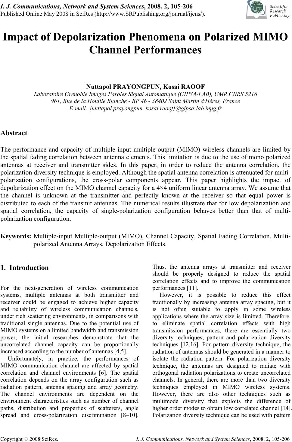 I. J. Communications, Network and System Sciences, 2008, 2, 105-206 Published Online May 2008 in SciRes (http://www.SRPublishing.org/journal/ijcns/). Copyright © 2008 SciRes. I. J. Communications, Network and System Sciences, 2008, 2, 105-206 Impact of Depolarization Phenomena on Polarized MIMO Channel Performances Nuttapol PRAYONGPUN, Kosai RAOOF Laboratoire Grenoble Images Paroles Signal Automatique (GIPSA-LAB), UMR CNRS 5216 961, Rue de la Houille Blanche - BP 46 - 38402 Saint Martin d'Hères, France E-mail: {nuttapol.prayongpun, kosai.raoof}@gipsa-lab.inpg.fr Abstract The performance and capacity of multiple-input multiple-output (MIMO) wireless channels are limited by the spatial fading correlation between antenna elements. This limitation is due to the use of mono polarized antennas at receiver and transmitter sides. In this paper, in order to reduce the antenna correlation, the polarization diversity technique is employed. Although the spatial antenna correlation is attenuated for multi- polarization configurations, the cross-polar components appear. This paper highlights the impact of depolarization effect on the MIMO channel capacity for a 4×4 uniform linear antenna array. We assume that the channel is unknown at the transmitter and perfectly known at the receiver so that equal power is distributed to each of the transmit antennas. The numerical results illustrate that for low depolarization and spatial correlation, the capacity of single-polarization configuration behaves better than that of multi- polarization configuration. Keywords: Multiple-input Multiple-output (MIMO), Channel Capacity, Spatial Fading Correlation, Multi- polarized Antenna Arrays, Depolarization Effects. 1. Introduction For the next-generation of wireless communication systems, multiple antennas at both transmitter and receiver could be engaged to achieve higher capacity and reliability of wireless communication channels, under rich scattering environments, in comparisons with traditional single antennas. Due to the potential use of MIMO systems on a limited bandwidth and transmission power, the initial researches demonstrate that the uncorrelated channel capacity can be proportionally increased according to the number of antennas [4,5]. Unfortunately, in practice, the performances of MIMO communication channel are affected by spatial correlation and channel environments [6]. The spatial correlation depends on the array configuration such as radiation pattern, antenna spacing and array geometry. The channel environments are dependent on the environment characteristics such as number of channel paths, distribution and properties of scatterers, angle spread and cross-polarization discrimination [8–10]. Thus, the antenna arrays at transmitter and receiver should be properly designed to reduce the spatial correlation effects and to improve the communication performances [11]. However, it is possible to reduce this effect traditionally by increasing antenna array spacing, but it is not often suitable to apply in some wireless applications where the array size is limitted. Therefore, to eliminate spatial correlation effects with high transmission performances, there are essentially two diversity techniques; pattern and polarization diversity techniques [12,16]. For pattern diversity technique, the radiation of antennas should be generated in a manner to isolate the radiation pattern. For polarization diversity technique, the antennas are designed to radiate with orthogonal radiation polarizations to create uncorrelated channels. In general, there are more than two diversity techniques employed in MIMO wireless systems. However, there are also other techniques such as multimode diversity that exploits the difference of higher order modes to obtain low correlated channel [14]. Polarization diversity technique can be used with pattern 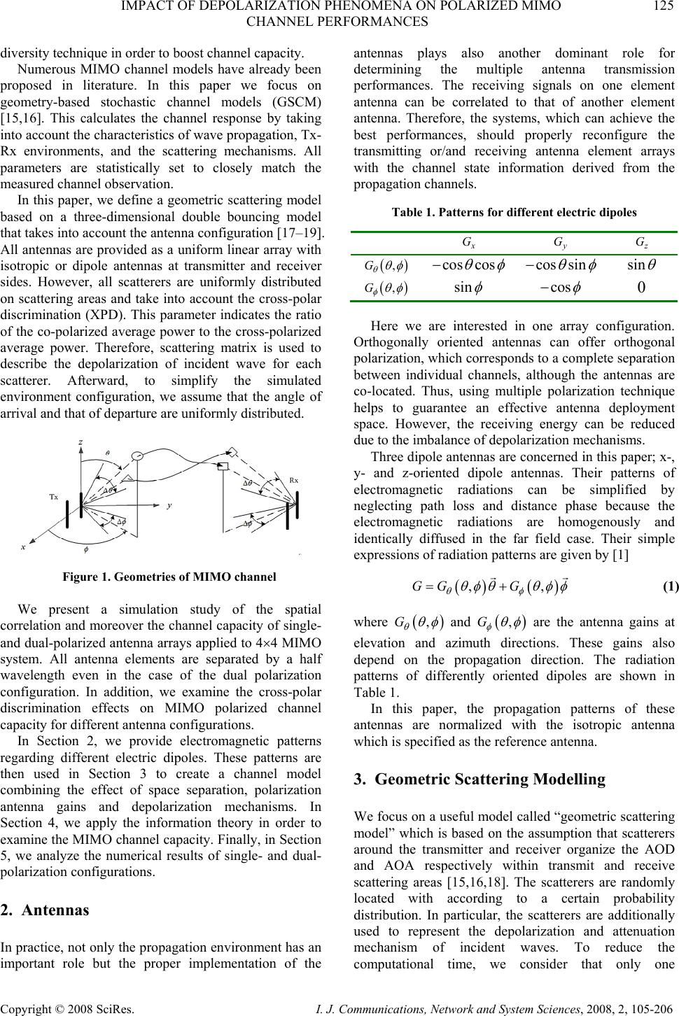 IMPACT OF DEPOLARIZATION PHENOMENA ON POLARIZED MIMO 125 CHANNEL PERFORMANCES Copyright © 2008 SciRes. I. J. Communications, Network and System Sciences, 2008, 2, 105-206 diversity technique in order to boost channel capacity. Numerous MIMO channel models have already been proposed in literature. In this paper we focus on geometry-based stochastic channel models (GSCM) [15,16]. This calculates the channel response by taking into account the characteristics of wave propagation, Tx- Rx environments, and the scattering mechanisms. All parameters are statistically set to closely match the measured channel observation. In this paper, we define a geometric scattering model based on a three-dimensional double bouncing model that takes into account the antenna configuration [17–19]. All antennas are provided as a uniform linear array with isotropic or dipole antennas at transmitter and receiver sides. However, all scatterers are uniformly distributed on scattering areas and take into account the cross-polar discrimination (XPD). This parameter indicates the ratio of the co-polarized average power to the cross-polarized average power. Therefore, scattering matrix is used to describe the depolarization of incident wave for each scatterer. Afterward, to simplify the simulated environment configuration, we assume that the angle of arrival and that of departure are uniformly distributed. Figure 1. Geometries of MIMO channel We present a simulation study of the spatial correlation and moreover the channel capacity of single- and dual-polarized antenna arrays applied to 4×4 MIMO system. All antenna elements are separated by a half wavelength even in the case of the dual polarization configuration. In addition, we examine the cross-polar discrimination effects on MIMO polarized channel capacity for different antenna configurations. In Section 2, we provide electromagnetic patterns regarding different electric dipoles. These patterns are then used in Section 3 to create a channel model combining the effect of space separation, polarization antenna gains and depolarization mechanisms. In Section 4, we apply the information theory in order to examine the MIMO channel capacity. Finally, in Section 5, we analyze the numerical results of single- and dual- polarization configurations. 2. Antennas In practice, not only the propagation environment has an important role but the proper implementation of the antennas plays also another dominant role for determining the multiple antenna transmission performances. The receiving signals on one element antenna can be correlated to that of another element antenna. Therefore, the systems, which can achieve the best performances, should properly reconfigure the transmitting or/and receiving antenna element arrays with the channel state information derived from the propagation channels. Table 1. Patterns for different electric dipoles x G y G z G ( ) ,G θ θ φ cos cos θ φ − cos sin θ φ − sin θ ( ) ,G φ θ φ sin φ cos φ − 0 Here we are interested in one array configuration. Orthogonally oriented antennas can offer orthogonal polarization, which corresponds to a complete separation between individual channels, although the antennas are co-located. Thus, using multiple polarization technique helps to guarantee an effective antenna deployment space. However, the receiving energy can be reduced due to the imbalance of depolarization mechanisms. Three dipole antennas are concerned in this paper; x-, y- and z-oriented dipole antennas. Their patterns of electromagnetic radiations can be simplified by neglecting path loss and distance phase because the electromagnetic radiations are homogenously and identically diffused in the far field case. Their simple expressions of radiation patterns are given by [1] ( )() ,,GG G θφ θ φθ θφφ =+ r r (1) where ( ) ,G θ θ φ and ( ) ,G φ θ φ are the antenna gains at elevation and azimuth directions. These gains also depend on the propagation direction. The radiation patterns of differently oriented dipoles are shown in Table 1. In this paper, the propagation patterns of these antennas are normalized with the isotropic antenna which is specified as the reference antenna. 3. Geometric Scattering Modelling We focus on a useful model called “geometric scattering model” which is based on the assumption that scatterers around the transmitter and receiver organize the AOD and AOA respectively within transmit and receive scattering areas [15,16,18]. The scatterers are randomly located with according to a certain probability distribution. In particular, the scatterers are additionally used to represent the depolarization and attenuation mechanism of incident waves. To reduce the computational time, we consider that only one 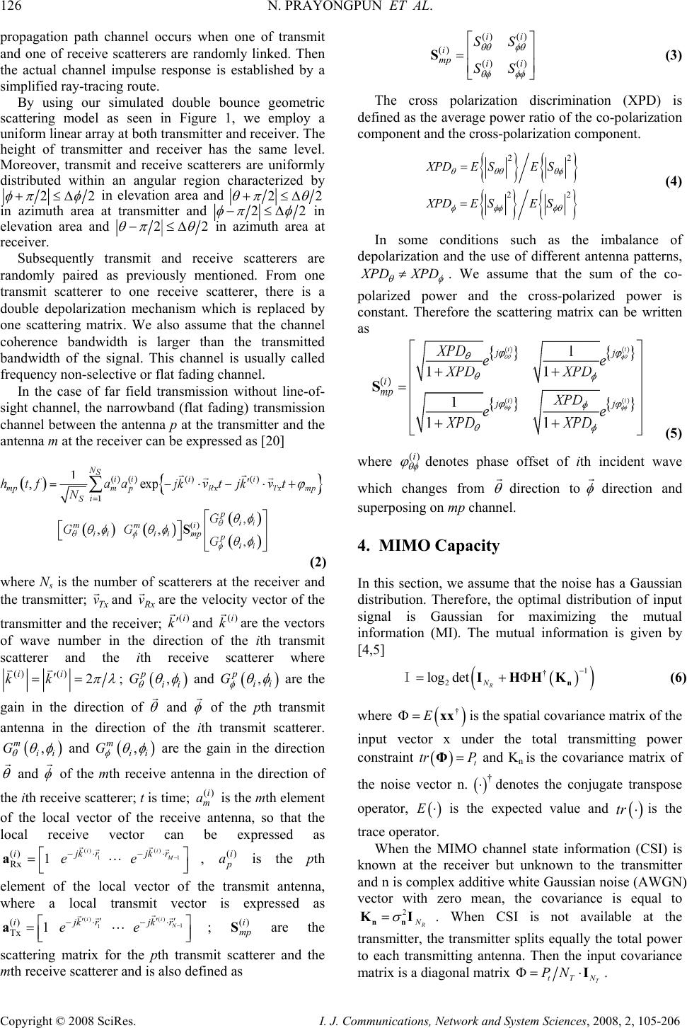 126 N. PRAYONGPUN ET AL. Copyright © 2008 SciRes. I. J. Communications, Network and System Sciences, 2008, 2, 105-206 propagation path channel occurs when one of transmit and one of receive scatterers are randomly linked. Then the actual channel impulse response is established by a simplified ray-tracing route. By using our simulated double bounce geometric scattering model as seen in Figure 1, we employ a uniform linear array at both transmitter and receiver. The height of transmitter and receiver has the same level. Moreover, transmit and receive scatterers are uniformly distributed within an angular region characterized by 22 φ πφ +≤∆ in elevation area and 22 θ πθ +≤∆ in azimuth area at transmitter and 22 φ πφ −≤∆ in elevation area and 22 θ πθ −≤∆ in azimuth area at receiver. Subsequently transmit and receive scatterers are randomly paired as previously mentioned. From one transmit scatterer to one receive scatterer, there is a double depolarization mechanism which is replaced by one scattering matrix. We also assume that the channel coherence bandwidth is larger than the transmitted bandwidth of the signal. This channel is usually called frequency non-selective or flat fading channel. In the case of far field transmission without line-of- sight channel, the narrowband (flat fading) transmission channel between the antenna p at the transmitter and the antenna m at the receiver can be expressed as [20] (2) where Ns is the number of scatterers at the receiver and the transmitter; Tx v rand Rx v rare the velocity vector of the transmitter and the receiver; ()i k ′ r and ()i k r are the vectors of wave number in the direction of the ith transmit scatterer and the ith receive scatterer where ()() 2 ii kk π λ ′ == vv ; () , p ii G θ θ φ and () , p ii G φ θφ are the gain in the direction of θ r and φ r of the pth transmit antenna in the direction of the ith transmit scatterer. () , m ii G θ θ φ and () , m ii G φ θ φ are the gain in the direction θ r and φ r of the mth receive antenna in the direction of the ith receive scatterer; t is time; ()i m a is the mth element of the local vector of the receive antenna, so that the local receive vector can be expressed as () () 11 () Rx 1 ii M ijk rjk r ee − −⋅ −⋅ ⎡⎤ =⎢⎥ ⎣⎦ a rr rr L, ()i p a is the pth element of the local vector of the transmit antenna, where a local transmit vector is expressed as () () 1 1 () Tx 1 i i N jk rijk r ee − ′′ ′′ −⋅ −⋅ ⎡⎤ =⎢⎥ ⎣⎦ a r rr r L; ()i mp S are the scattering matrix for the pth transmit scatterer and the mth receive scatterer and is also defined as () () () () () ii i mp ii SS SS θ θφθ θ φφφ ⎡ ⎤ ⎢ ⎥ = ⎢ ⎥ ⎣ ⎦ S (3) The cross polarization discrimination (XPD) is defined as the average power ratio of the co-polarization component and the cross-polarization component. { } { } {}{} 22 22 XPD ESES XPD ESES θθθ θφ φφφ φθ = = (4) In some conditions such as the imbalance of depolarization and the use of different antenna patterns, X PD XPD θ φ ≠ . We assume that the sum of the co- polarized power and the cross-polarized power is constant. Therefore the scattering matrix can be written as (5) where ()i θ φ ϕ denotes phase offset of ith incident wave which changes from θ r direction to φ r direction and superposing on mp channel. 4. MIMO Capacity In this section, we assume that the noise has a Gaussian distribution. Therefore, the optimal distribution of input signal is Gaussian for maximizing the mutual information (MI). The mutual information is given by [4,5] () ( ) 1 † 2 log detR N − =+Φ n IHHKI (6) where ( ) † EΦ= xx is the spatial covariance matrix of the input vector x under the total transmitting power constraint ( ) t tr P = Φ and Kn is the covariance matrix of the noise vector n. () † ⋅ denotes the conjugate transpose operator, ( ) E ⋅ is the expected value and ( ) tr ⋅ is the trace operator. When the MIMO channel state information (CSI) is known at the receiver but unknown to the transmitter and n is complex additive white Gaussian noise (AWGN) vector with zero mean, the covariance is equal to 2 R N σ = nn KI. When CSI is not available at the transmitter, the transmitter splits equally the total power to each transmitting antenna. Then the input covariance matrix is a diagonal matrix T tTN PNΦ= ⋅I.  IMPACT OF DEPOLARIZATION PHENOMENA ON POLARIZED MIMO 127 CHANNEL PERFORMANCES Copyright © 2008 SciRes. I. J. Communications, Network and System Sciences, 2008, 2, 105-206 (a) (b) Figure 2. 4×4 MIMO channel capacity of isotropic antennas: (a) single-polarization system and (b) dual- polarization system Therefore, the average MI, E(I), called the ergodic channel capacity, with equal-power allocation at transmitter can be written as () 22 log detR H t noCSI N T P CEE N σ ⎡⎤ ⎛⎞ == + ⎢⎥ ⎜⎟ ⎝⎠ ⎣⎦ H n IHHI (7) By applying an eigenvalue decomposition, (7) can be rewritten as 2 2, 2 1 log 1 M t noCSI i iT P CE N λ σ = ⎡⎤ ⎛⎞ =+ ⎢⎥ ⎜⎟ ⎝⎠ ⎣⎦ ∑ HH (8) where M = min(NT,NR) that corresponds to the rank of channel matrix and 2 ,i λ H is the ith eigenvalue of H. 5. Simulation Results Based on Geometric Scattering Modelling 5.1. Capacity Versus Angle Spread The antenna correlation effect is an important indicator for transmission performance since lower correlation will tend to produce higher mean channel capacity for single polarization system as seen in Figure 2. Thus employing polarization and angular diversity techniques is an attractive way to improve MIMO systems. The 4×4 MIMO systems employ isotropic antennas for λ/2 antenna spacing as shown in Figure 1. In order to estimate the channel capacity of different antenna configuration, the simulated environments must be identical. Hence the channel capacities are studied in terms of different antenna configurations. The radiation patterns of each antenna are normalized by the radiation pattern of an isotropic antenna. As mentioned in previous section, the distribution of angles of departure is assumed to have a uniform elevation distribution 22 φ πφ +≤∆ and a uniform arrival azimuth distribution 22 θ πθ +≤∆ and the distribution of angles of arrival is assumed to have a uniform elevation distribution 22 φ πφ −≤∆ and a uniform arrival azimuth distribution 22 θ πθ −≤∆ where AS φ θ ∆ =∆ = and XPDθ=XPDØ=XPD=0dB with 20 scatterers at both transmitter and receiver and 15 dB of SNR. The aim of this section is to study the effects of angle spreads and antenna radiation patterns in terms of ergodic capacity. Figure 2 demonstrates 4×4 MIMO channel capacity of single and dual polarized configuration. For single- polarization case, only azimuth isotropic antennas are employed and for dual-polarization case, we put successively azimuth and elevation isotropic antennas in order with λ/2 antenna spacing. From Figure 2a, the MIMO channel capacity increases as the angle spread increases at transmitter and receiver for the same polarization antennas. In contrast, the dual polarization achieves better channel capacity due to the lower antenna correlation. It founds that the MIMO channel capacity is significantly dependent on the antenna correlation. The polarization diversity technique can diminish the spatial correlation effect and improve the system performances as shown in Figure 2b. Figure 3. Difference between dual-polarized and single- polarized channel capacity of 4×4 MIMO systems in functions of XPD and AS 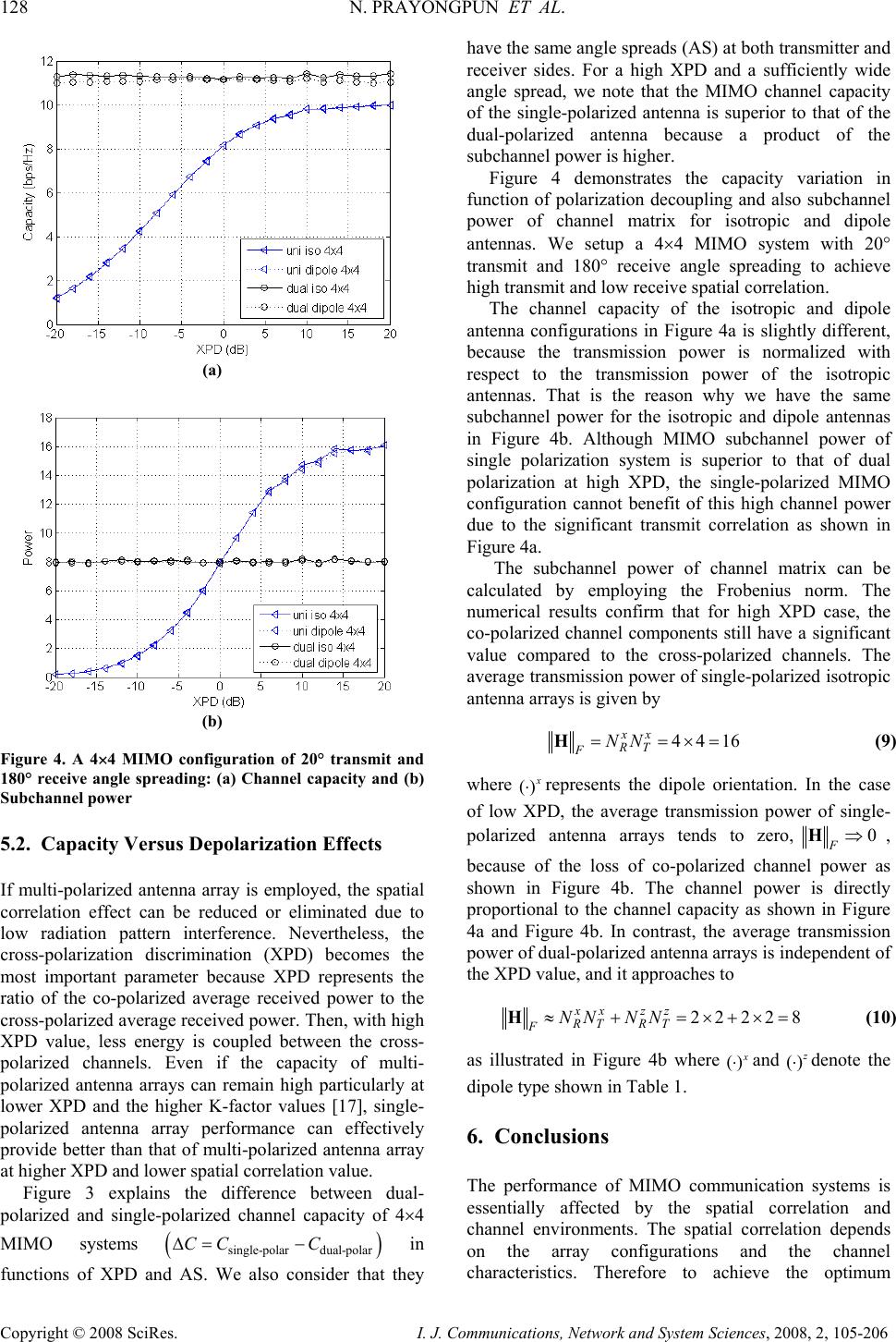 128 N. PRAYONGPUN ET AL. Copyright © 2008 SciRes. I. J. Communications, Network and System Sciences, 2008, 2, 105-206 (a) (b) Figure 4. A 4×4 MIMO configuration of 20° transmit and 180° receive angle spreading: (a) Channel capacity and (b) Subchannel power 5.2. Capacity Versus Depolarization Effects If multi-polarized antenna array is employed, the spatial correlation effect can be reduced or eliminated due to low radiation pattern interference. Nevertheless, the cross-polarization discrimination (XPD) becomes the most important parameter because XPD represents the ratio of the co-polarized average received power to the cross-polarized average received power. Then, with high XPD value, less energy is coupled between the cross- polarized channels. Even if the capacity of multi- polarized antenna arrays can remain high particularly at lower XPD and the higher K-factor values [17], single- polarized antenna array performance can effectively provide better than that of multi-polarized antenna array at higher XPD and lower spatial correlation value. Figure 3 explains the difference between dual- polarized and single-polarized channel capacity of 4×4 MIMO systems () single-polar dual-polar CC C∆= − in functions of XPD and AS. We also consider that they have the same angle spreads (AS) at both transmitter and receiver sides. For a high XPD and a sufficiently wide angle spread, we note that the MIMO channel capacity of the single-polarized antenna is superior to that of the dual-polarized antenna because a product of the subchannel power is higher. Figure 4 demonstrates the capacity variation in function of polarization decoupling and also subchannel power of channel matrix for isotropic and dipole antennas. We setup a 4×4 MIMO system with 20° transmit and 180° receive angle spreading to achieve high transmit and low receive spatial correlation. The channel capacity of the isotropic and dipole antenna configurations in Figure 4a is slightly different, because the transmission power is normalized with respect to the transmission power of the isotropic antennas. That is the reason why we have the same subchannel power for the isotropic and dipole antennas in Figure 4b. Although MIMO subchannel power of single polarization system is superior to that of dual polarization at high XPD, the single-polarized MIMO configuration cannot benefit of this high channel power due to the significant transmit correlation as shown in Figure 4a. The subchannel power of channel matrix can be calculated by employing the Frobenius norm. The numerical results confirm that for high XPD case, the co-polarized channel components still have a significant value compared to the cross-polarized channels. The average transmission power of single-polarized isotropic antenna arrays is given by 4416 xx RT FNN = =×=H (9) where () x ⋅ represents the dipole orientation. In the case of low XPD, the average transmission power of single- polarized antenna arrays tends to zero,0 F⇒H, because of the loss of co-polarized channel power as shown in Figure 4b. The channel power is directly proportional to the channel capacity as shown in Figure 4a and Figure 4b. In contrast, the average transmission power of dual-polarized antenna arrays is independent of the XPD value, and it approaches to 2222 8 ≈ +=×+×=Hxx zz RT RT FNN NN (10) as illustrated in Figure 4b where () x ⋅and () z ⋅denote the dipole type shown in Table 1. 6. Conclusions The performance of MIMO communication systems is essentially affected by the spatial correlation and channel environments. The spatial correlation depends on the array configurations and the channel characteristics. Therefore to achieve the optimum 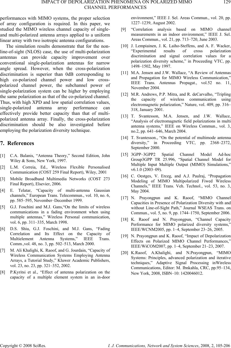 IMPACT OF DEPOLARIZATION PHENOMENA ON POLARIZED MIMO 129 CHANNEL PERFORMANCES Copyright © 2008 SciRes. I. J. Communications, Network and System Sciences, 2008, 2, 105-206 performances with MIMO systems, the proper selection of array configuration is required. In this paper, we studied the MIMO wireless channel capacity of single- and multi-polarized antenna arrays applied to a uniform linear array with two isotropic antenna configurations. The simulation results demonstrate that for the non- line-of-sight (NLOS) case, the use of multi-polarization antennas can provide capacity improvement over conventional single-polarization antennas for narrow angle spread. However, when the cross-polarization discrimination is superior than 0dB corresponding to high co-polarized channel power and low cross- polarized channel power, the subchannel power of single-polarization system can be higher by employing the same polarization as that of the co-polarized channel. Thus, with high XPD and low spatial correlation values, single-polarized antenna array performance can effectively provide better capacity than that of multi- polarized antenna array. Finally, the cross-polarization discrimination should be also investigated before employing the polarization diversity technique. 7. References [1] C.A. Balanis, “Antenna Theory,” Second Edition, John Wiley & Sons, New York, 1997. [2] L.M. Correia, Ed., Wireless Flexible Personalised Communication (COST 259 Final Report), Wiley, 2001 [3] Mobile Broadband Multimedia Networks (COST 273 Final Report), Elsevier, 2006. [4] E. Telatar, “Capacity of multi-antenna Gaussian channels,” European Trans. Telecommun., vol. 10, no. 6, pp. 585–595, November–December 1999. [5] G.J. Foschini and M.J. Gans,“On the limits of wireless communications in a fading environment when using multiple antennas,” Wireless Personal communication, vol. 6, pp. 311–335, March 1998. [6] D.S. Shiu, G.J. Foschini, and M.J. Gans, “Fading Correlation and Its Effect on the Capacity of Multielement Antenna Systems,” IEEE Trans. Comm.,vol. 48, no. 3, pp. 502–513, March 2000. [7] M. Ali Khalighi, K. Raoof, and G. Jourdain, “Capacity of Wireless Communication Systems Employing Antenna Arrays, a Tutorial Study,” Kluwer Academic Publishers, vol. 23, no. 23, pp. 321–352, 2002. [8] P.Kyritsi et al., “Effect of antenna polarization on the capacity of a multiple element system in an in-door environment,” IEEE J. Sel. Areas Commun., vol. 20, pp. 1227–1239, August 2002. [9] “Correlation analysis based on MIMO channel measurements in an indoor environment,” IEEE J. Sel. Areas Commun., vol. 21, pp. 713–720, June 2003. [10] J. Lempiainen, J. K. Laiho-Steffens, and A. F. Wacker, “Experimental results of cross polarization discrimination and signal correlation values for a polarization diversity scheme,” in Proceeding VTC, pp. 1498–1502, May 1997. [11] M.A. Jensen and J.W. Wallace, “A Review of Antennas and Propagation for MIMO Wireless Communication,” IEEE Trans. Antennas Propagat., vol.52 no. 11, November 2004. [12] M.R. Andrews, P.P. Mitra, and R. deCarvalho, “Tripling the capacity of wireless communication using electromagnetic polarization,” Nature, vol. 409, pp. 316– 318, January 2001. [13] T. Svantesson, M.A. Jensen, and J.W. Wallace, “Analysis of electromagnetic field polarizations in multi antenna systems,” IEEE on Wireless Commun., vol. 3, no.2, pp. 641–646, March 2004. [14] T. Svantesson., “On the potential of multimode antenna diversity,” in Proceeding VTC, pp. 2368–2372, September 2000. [15] 3GPP–3GPP2 Spatial Channel Model Ad-hoc Group3GPP TR 25.996, “Spatial Channel Model for Multiple Input Multiple Output (MIMO) Simulations,” v6.1.0 (2003–09). [16] C. Oestges, V. Erceg, and A.J. Paulraj, “Propagation Modeling of MIMO Multipolarized Fiwed Wireless Channels,” IEEE Trans. Veh. Technol., vol. 53, no. 3, May 2004. [17] N. Prayongpun and K. Raoof, “MIMO Channel Capacities in Presence of Polarization Diversity with and without Line-of-Sight Path,” Journal WSEAS Trans. on Commun., vol. 5, no. 9, pp. 1744–1750, September 2006. [18] K. Raoof and N. Prayongpun, “Channel Capacity Performance for MIMO polarized diversity systems,” IEEE/WCNM2005, pp. 1–4, September 23–26, 2005. [19] N. Prayongpun and K. Raoof, “Impact of Depolarization Effects on Polarized MIMO Channel Performances,” IEEE/WiCOM2007, pp. 1–4, September 21–23, 2007. [20] K.Raoof, A.Khalighi, and N.Prayongpun, “MIMO Systems: Principles, advanced polarization and iterative techniques,” Adaptive Signal Processing inWireless Communications, Editor: M. Ibnkahla, CRC, pp.95–134, New York, 2008, ISBN–10: 1420046012. |