 Journal of Power and Energy Engineering, 2014, 2, 22-29 Published Online June 2014 in SciRes. http://www.scirp.org/journal/jpee http://dx.doi.org/10.4236/jpee.2014.26003 How to cite this paper: Tongbai, P. and Chitsomboon, T. (2014) Enhancements of Roof Solar Chimney Performance for Building Ventilation. Journal of Power and Energy Engineering, 2, 22-29. http://dx.doi.org/10.4236/jpee.2014.26003 Enhancements of Roof Solar Chimney Performance for Building Ventilation Pornsawan Tongbai, Tawit Chitsomboon School of Mechanical Engineering, Institute of Engineering, Suranaree University of Technology, Nakhon Ratchasima, Thailand Email: ptongbai@hotmail. com Received April 2014 Abstract A roof solar chimney (RSC) is inclined in the roof of a building wherein solar radiation is employed to heat the air the channel. The hot air flows up the channel which can be used to induce flow out of the building in order to ventilate it. In this study, parameters that affect the performance of this natural ventilation system were investigated numerically, namely: inclination angles, channel gaps, solar intensities, vertical chimney attachment heights and channel expanding angles. The two last parameters were new concepts that seem to have never been studied before. All of the mentioned parameters were found to exhibit positive effects on the ventilation. Relative merits of these techniques were compared and discussed. Keywords Natural Ventilation, Natural Ventilation Enhancement, Solar Attic, Solar Chimney, Expanding Channel 1. Introduction The concept of solar chimney has been employed since ancient past to induce flows to ventilate buildings. Re- cently it has been adapted to be an electricity generating device [1]-[3]. Building ventilation, however, has been the main application area of this concept [4]-[18]. In this method air contained between a parallel channel, nor- mally under a building’s roof, or in a vertical chimney, is heated by solar heat flux so that its density is reduced. The lighter air is “pulled” by buoyancy to flow upward through the inclined channel or a chimney or a chim- ney-liked structure. The upwardly flowing air is manipulated to induce the surrounding air to ventilate the building. The concept is very simple but to design a good ventilating system based on this principle requires a great deal of theoretical knowledge and proven experimental data. Bansal et al. [4] [5] developed a theoretical model to predict that a solar chimney system could induced air flow around 50 - 165 m3/h per 1 m2 of solar collector area. They also found, both theoretically and experimen- tally, that the cross sectional area and the height of a solar chimney could significantly affect the air flow rate. Gan [6] also found similarly but noted that a chimney that was too high could induce a reversed flow near its top. Beneficial effects of channel width, height, and solar intensity were confirmed by Bouchair [7], Burek and Ha- 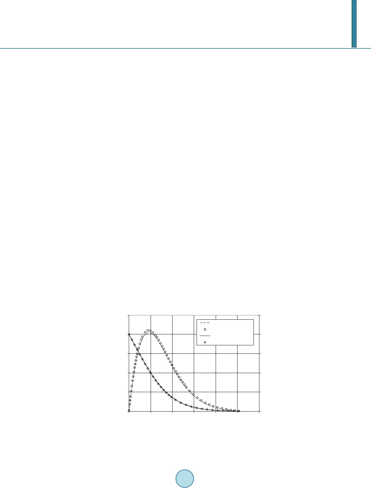 P. Tongbai, T. Chitsomboon beb [8] and Afonso and Oliveira [9]. The study of Hamdy and Fikry [10] reported that roof inclination of 60˚ produced the best results. Zhai found that roof inclination could be reduced, while increasing efficiency, by using a double channel set up instead of a single channel. Several works on roof solar chimney (RSC) had been conducted by Hirunlabh et al. and Khedari et al. [12] [13]-[16]. Their collective works had suggested that the best roof channel widths should be 10 - 14 cm and optimal lengths of 1 - 2 m, while the inclination angles should be 20˚ - 45˚. Tongbai and Chitsomboon pro- posed a vertical chimney attachment on top of the roof channel structure and found additional benefit [17]. From the literature reviewed above it can be concluded that air flow rate through RSC was found to be basi- cally dependent on: solar intensity, chimney height (or roof inclination), channel width, chimney attachment as well as manipulations on the configurations. The qualitative trends of past researches agreed well with one another but with some quantitative differences. The recent works of Tongbai and Chitsomboon [18] [19] have found that expansions of the channel along the flow path could also help increase the air flow rate. This finding was based on an analysis of the theoretical model of Chitsomboon [1] and was confirmed by Koonsrisuk and Chitsomboon [20] in the context of a solar chimney for electricity generation. The main objectives of this study were to reinvestigate the beneficial effects (or the lack thereof) of all the mentioned parameters in a wider range and to compare their relative merits. By using the same tool for these in- vestigations the results could be compared more credibly than before. Another objective was to introduce the concept of using the expanding channel to a wider audience since up until now it was circulated only within a small research community of Thailand. 2. Methodology ANSYS CFX, Release 11.0 [21] is the basic CFD (Computational Fluid Dynamics) tool that was used in this study. The CFD code was based on the finite volume methodology with the unstructured grid. Before endeavor- ing into the computation, the program was validated by solving for a free convective flow over a heated flat plate. Good comparisons of the computed results with those of the similarity method [22] in Figure 1 help es- tablish confidence in the forthcoming computations. A schematic of the full-featured roof solar chimney is as shown in Figure 2. In this configuration the air channel is expanding along the flow path (with the angle, β) and a vertical chimney is also attached at the exit. The conditions used for the computational test cases are as indicated in Table 1. Assumptions and conditions used in this study were as follows: Two-dimensional air channel. Uniform volumetric heat source to simulate the solar heat absorption. Figure 1. Comparison of velocity and temperature profiles between CFD and theory for buoyant boundary layer flow along a vertical flat plate. 0.00 0.10 0.20 0.30 0.40 0.50 0.000 0.002 0.004 0.006 0.008 0.010 0.012 Distance from flat plate (m) Velocity from theory Velocity from CFD Temperature from theory Temperature from CFD 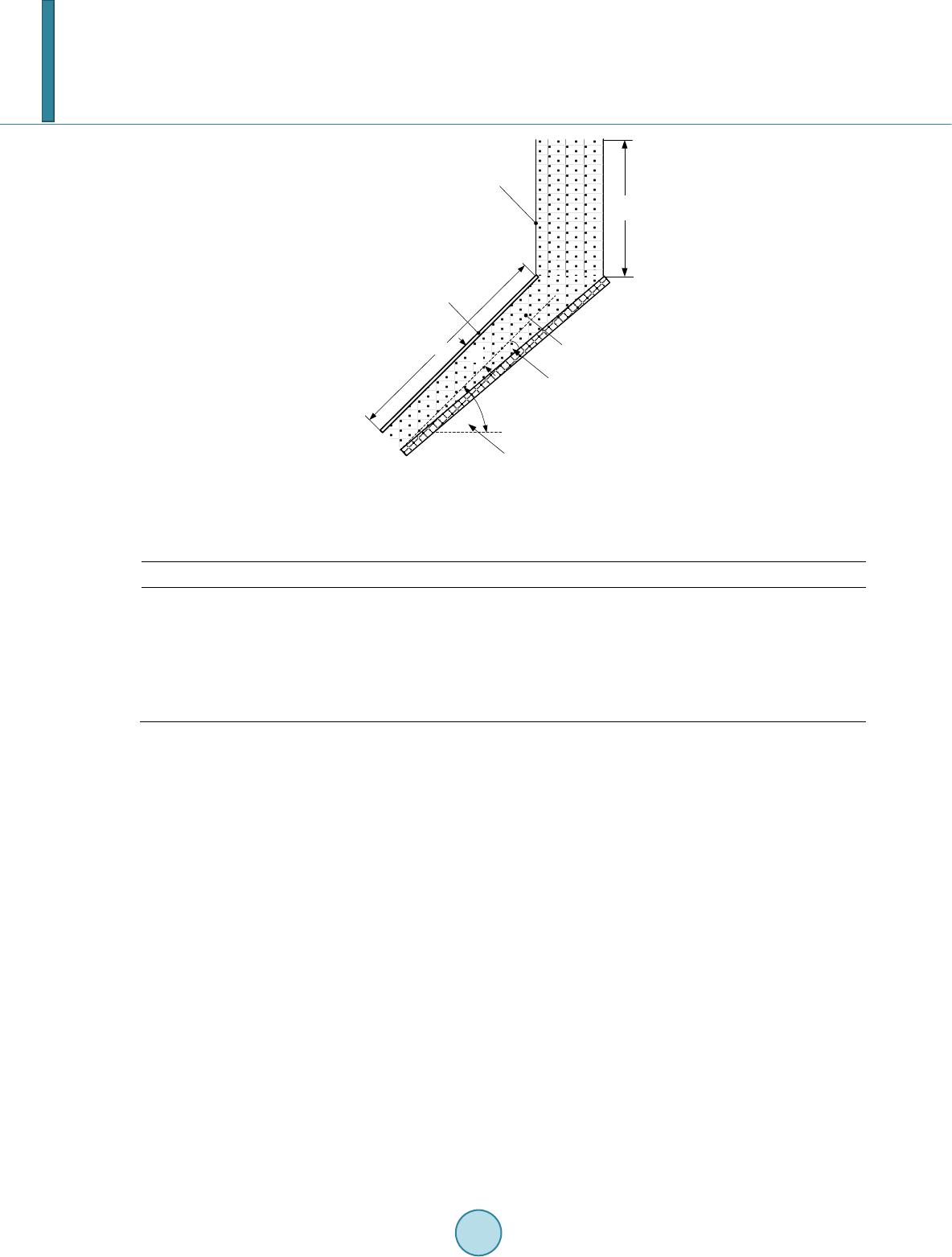 P. Tongbai, T. Chitsomboon β θ Ld Transparent roof Air gap chimney c h Channel expansion angle Roof inclination angle Figure 2. Schematic of the roof solar chimney. Table 1. Conditions used in the computational test cases. Case increment β d, cm L, m hc, m (W/m2) Channel expansion, β 1˚ 0˚ - 12˚ 14 1 0 500, 650, 800, 900 Channel gap, d 2˚ 0 10 - 60 1 0 500, 650, 800, 900 Inclination angle of Roof, θ 15˚ 0 10, 30 Dependent to θ 0 650 Chimney attachment height, hc 0.25 m 0, 4° 14 1 0 - 1.25 800 Overall height of roof, ho - 0 14 - - 800 Laminar flow (low Grashof number). Boussinesq’s approximation for density change due to heat. Numerical convergence deemed by RMS residuals and mass flow rates in channel The second assumption is plausible because we are more interested in qualitative solution rather than quantitative solution. In other words, we are interested in the macroscopic behavior of the flow so that we can observe trends and relative merits of each technique. Detailed heat transfer models certainly will improve quantitative results slightly but should not change trends and qualitative behaviors of the solutions. 3. Result and Discussion 3.1. Effects of Channel Expansion Angles Figure 3 indicates that the flow rate increases with the channel expansion angle. The relationships are almost linear to about 5 degree and decline gradually thereafter. The declines were probably due to the flow being se- parated from the wall which is often observed for flow in a diffuser. At about 6˚ expansion the flow rate in- creased by about 24% over the no expansion case. This is quite significant and it offers a new means to enhance the ventilation rate. Experiments are needed here to confirm the findings of this study. The reason behind the increase of the flow rate is perhaps that of the diffuser effect whereby the flow at inlet can increase its velocity and hence reduces its pressure according to the Bernoulli’s principle. The low pressure at the inlet can be recovered through the expanding channel (again by the Bernoulli’s principle) and equilibrate itself with that of the surrounding at the exit. Observe also that the graphs wiggle at about 7 degree expansion; this was due to the mentioned flow separations. More expansions beyond the separation limit cause the air flow rates to reduce for all insolations due to increased frictions caused by progressively larger flow separations. 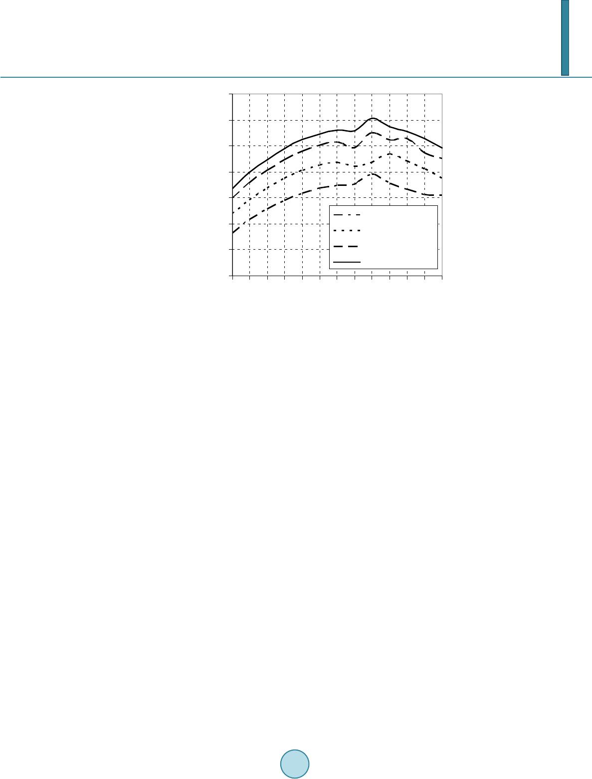 P. Tongbai, T. Chitsomboon Figure 3. Air mass flow rates per projected area of roof due to channel ex- pansion angle (L = 1 m, θ = 45˚, d = 14 cm). 3.2. Effects of Air Gap Like previous researchers, we found that the increase of air gap (channel width) could increase the flow rate. In Figure 4, it is evident that the air flow rates increase approximately linearly with the air gaps. At low insolation when the air gap is increased from 10 cm to 60 cm the air flow rates increase as much as 250%. Our finding here, however, contradicts Khedari et al.’s finding [12] wherein they reported that the optimal air gap should be about 14 - 16 cm for a 1m long channel, beyond which a decreased flow rate resulted. The contradiction with Khedari et al.’s findings could be due to the fact that in Khedari et al.’s experiment the increased air gaps helped promote heat losses to the sides of the channel while in our numerical investigations such losses were ignored. If this is really the case then it suggests that sidewall insulation is very important. It is interesting to note that as the air gap is widen the air temperature is reduced, hence the reduction of the buoyant driving force and air velocity. But it seems that the increase of the cross sectional area overcompensates the reduced velocity such that air mass flow rate increases. This could be a subject of further theoretical and ex- perimental investigations. 3.3. Effects of Roof Inclinations In this study the roof inclination was increased while keeping the base (horizontal) length constant; thus, the height increases with the inclination. The base length was set as the projected area of the 2 m long RSC inclined at 15˚. With this set up the total solar heat added were the same for all cases; any changes in the flow rate were due solely to the roof inclination. It is not a surprise to see that the flow rate increases with the roof inclination, as is shown in Figure 5. At air gap of 10 cm when the angles increase from 15˚ to 45˚ the ventilation increases by about 90%; this is quite significant. The rates of increase of the flow rates appear to be almost linear. The general reason for the increase simply is the stack effect due to the increase of the vertical height of the channel. A steep roof obviously performs better but its accompanying cost and architectural connotation must also be considered in a ventilation design. The mild bend down at 30˚ and bend up 60˚ of the graphs are believed to be the effect of the height being increased with and the bends here are characteristic of curve. 3.4. Effects of Chimney Attachment Several past studies had been conducted on solar chimney in building ventilation but they used chimneys also as 0.06 0.07 0.08 0.09 0.10 0.11 0.12 0.13 0 12 34 5 67 891011 12 Channel expansion angle ( ° ) Air mass flow rate per roof area (kg/s - m 2 ) Q = 500 W/m^2 Q = 650 W/m^2 Q = 800 W/m^2 Q = 900 W/m^2 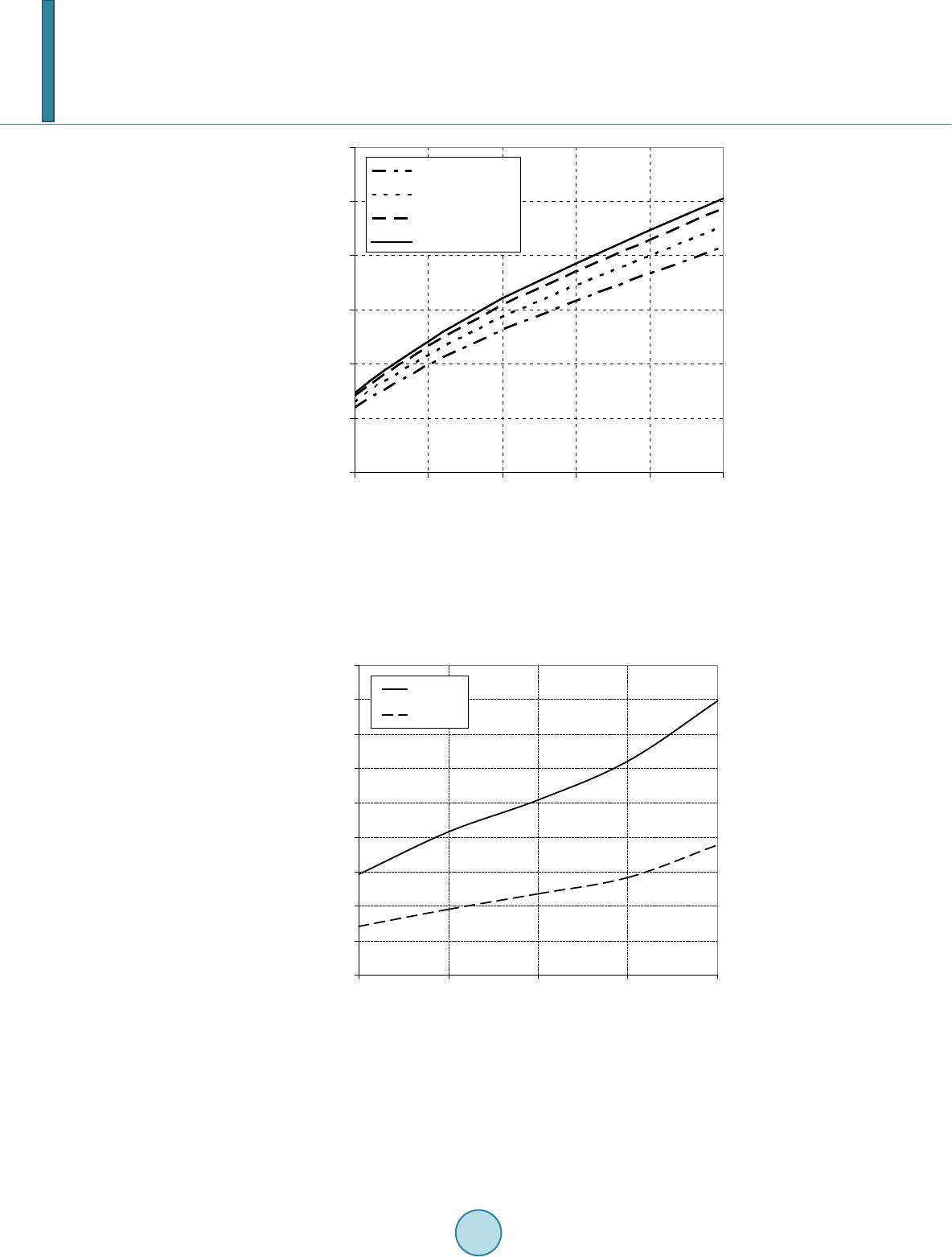 P. Tongbai, T. Chitsomboon Figure 4. Air mass flow rates per projected area of roof due to air gap varia- tion (L = 1 m, θ = 45˚). Figure 5. Air mass flow rates per projected area of roof due to roof length and roof angles ( = 650 W/m2, β = 0˚). a means to collect solar radiation, either in a vertical or an inclined arrangements. In this study a vertical chim- ney is attached to the inclined channel’s exist mainly to provide an additional height for the system and not for the purpose of adding heat; this is more plausible to the tropical part of the world where the sun is high. The re- 0.00 0.05 0.10 0.15 0.20 0.25 0.30 10 2030 4050 60 Air mass flow rate per roof erea (kg/s-m 2 ) Q = 500 W/m^2 Q = 650 W/m^2 Q = 800 W/m^2 Q = 900 W/m^2 0.00 0.02 0.04 0.06 0.08 0.10 0.12 0.14 0.16 0.18 15 30 45 60 75 Air mass flow rate per roof area (kg/s-m 2 ) Inclination angle of roof ( °) Overall height of the structure (m) 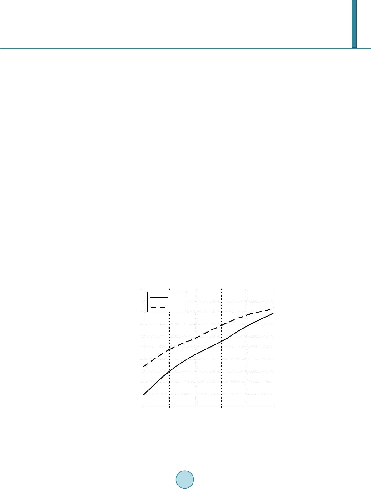 P. Tongbai, T. Chitsomboon sults, shown in Figure 6, indicate an increase of the flow rate with the height of the vertical chimney attachment. In this configuration the roof angle was 45˚ and the roof length was 1 m, giving the roof height of 0.71 m by at- taching the “passive” vertical chimney for another 1 m the flow rate increase by about 67%. The results of the case for β = 4˚ are also shown in the plot. In this case only the roof portion was expanded while the chimney portion was straight. The advantage of the expansion angle is seen to be lesser as the chimney is longer. This is believed to be due to the effect of lesser buoyant force caused by a lower air temperature in the expanded roof The Chimney attachment offers a new design alternative with different architectural appeals as well as cost. 3.5. Chimney V.S. No Chimney In this design, a flat roof is combined with a vertical chimney to give the same overall height as the inclined roofs without chimneys. From an engineering point of view it is interesting to see whether the two designs, with the same overall height, will produce similar flow rate. Figure 7 provides the comparisons of the two systems wherein it is seen that the roof without a chimney performs slightly better. At the chimney height of 1 m the air flow rate reduced by about 15% below the level of the no-chimney condition. This is believed to be the effect of friction since the flow has to turn a sharp corner formed at the juncture of the flat roof and the vertical chimney. It is obvious that, a combination of a less inclined roof with a chimney attachment can be made to give the same total mass flow rate as a more inclined roof. 4. Conclusion The numerical study performed in this study has confirmed the trends of some of the previous studies in the past, namely that flow rates in solar chimney for building ventilations increase with air gap, roof inclination and inso- lation level. Wider air gaps helped increase the ventilation most significantly, up to 250% as the gap increased from 10 to 60 cm. The continuous increase of ventilation with the air gap contradicts the finding of a past inves- tigation which proposed an optimal air gap width. This contradiction is believed to be due to the heat losses to the side panels which were not included in this study. Two new concepts, namely, the longitudinally expanded channel and the (passive) vertical chimney attachment, have been introduced and found to help increase the ven- tilation rate even further and quite significantly. These new concepts offer new design alternatives for the natural ventilation of a building. Figure 6. Air mass flow rate per projected area of roof due to chimney height (d = 14 cm, = 800 W/m2). 0.08 0.09 0.10 0.11 0.12 0.13 0.14 0.15 0.16 0.17 0.18 0.00 0.25 0.50 0.75 1.00 1.25 Air mass flow rate per roof area (kg/s-m 2 ) 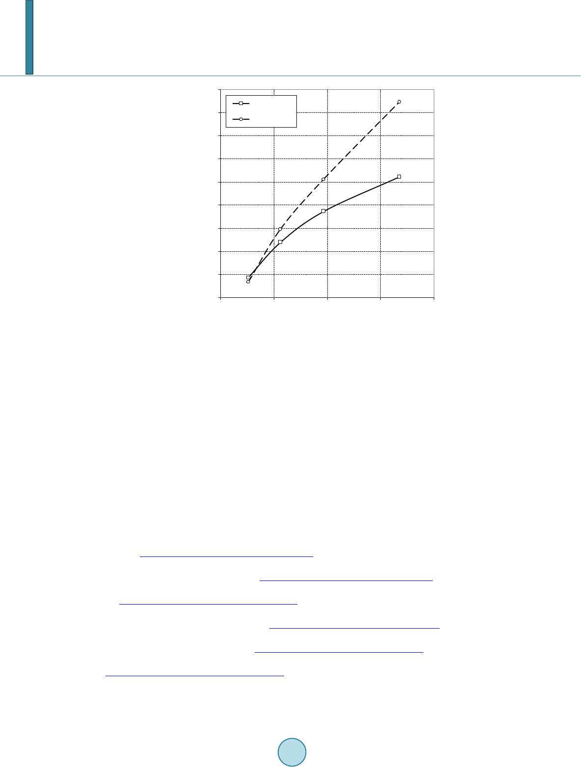 P. Tongbai, T. Chitsomboon Figure 7. Air mass flow rate per projected area of roof due to overall height of chimney (d = 14 cm, β = 0˚, = 800 W/m2). Acknowledgments The authors are grateful for the fund from Office of the Higher Education Commission under Higher Education Research Promotion Project. References [1] Chitsomboon, T. (2000) A Validated Analytical Model for Flow in Solar Chimney. International Journal of Renewable Energy Engineering, 3, 339-346. [2] Chitsomboon, T. and Tongbai, P. (1998) A Mathematical Model of Solar Chimney for Electrical Energy Production. Proceedings of the 12th National Mechanical Engineering Conference, Chulalongkorn University, Thailand, 14-20. [3] Chitsomboon, T. and Tongbai, P. (1999) The Effect of Chimney-Top Convergence on Efficiency of a Solar Chimney. Proceedings of the 13th National Mechanical Engineering Conference, Pataya, Thailand, 263-268. [4] Bansal, N.K . , Mathur, R. and Bha ndari, M. S. (1993) Solar Chimney Stack Ventilation. Building and Environment, 28, 373-377. http://dx.doi.org/10.1016/0360-1323(93)90042-2 [5] Bansal, N.K., Mathur, J., Mathur, S. and Jane, M. (2005) Modeling of Window-Sized Solar Chimneys for Ventil ation. Building and Environment, 40, 1302-1308. http://dx.doi.org/10.1016/j.buildenv.2004.10.011 [6] Gan, G. (1998) A Parametric Study of Trombe Walls for Passive Cooling of Buildings. Energy and Buildings, 27, 37- 43. http://dx.doi.org/10.1016/S0378-7788(97)00024-8 [7] Bouchair, A. (1994) Solar Chimney for Promoting Cooling Ventilation in Southern Algeria. Building Services Engi- neering Research and Technology, 15, 81-93. http://dx.doi.org/10.1177/014362449401500203 [8] Burek, S.A.M. and Habeb, A. (2007) Air Flow and Thermal Efficiency Characteristics in Solar Chimneys and Trombe Walls. Energy and Buildings, 3, 128-135. http://dx.doi.org/10.1016/j.enbuild.2006.04.015 [9] Afonso, C. and Oliviera, A. (2000) Solar Chimneys: Simulation and Experiment. Energy and Buildings, 32, 71-79. http://dx.doi.org/10.1016/S0378-7788(99)00038-9 [10] Hamdy, L.F. and Fik ry, M. A. (1998) Passive Solar Ventilation. Renewable Energy, 14, 381-386. [11] Zhai, X.Q., Dai, Y. J. and Wang, R.Z. (2005) Comparison of Heating and Natural Ventilation in a Solar House Induced 0.04 0.05 0.06 0.07 0.08 0.09 0.10 0.11 0.12 0.13 0.0 0.5 1.0 1.5 2.0 Air mass flow rate per roof area (kg/s-m 2 ) Overall height of roof (m)  P. Tongbai, T. Chitsomboon by Two Roof Solar Collectors. Applied Thermal Engineering, 25, 741-757. http://dx.doi.org/10.1016/j.applthermaleng.2004.08.001 [12] Hirunlabh, J., Washirapuwadon, S., Pratinthong, N. and Khedari, J. (2001) New Configurations of a Roof Solar Col- lector Maximizing Natural Ventilation. Building and Environment, 36, 383-391. http://dx.doi.org/10.1016/S0360-1323(00)00016-0 [13] Khedari, J., Hirunlabh, J. and Bunnag, T. (1997) Experimental Study of a Roof Solar Collector towards the Natural Ventilation of New Houses. Energy and Buildings, 26, 159-164. http://dx.doi.org/10.1016/S0378-7788(96)01030-4 [14] Khedari, J., Mansirisub, W. , Chaima, S., Pratinthong, N. and Hirunlabh, J. (2000) Field Measurements of Performance of Roof Solar Collector. Energy and Buildings, 31, 171-178. http://dx.doi.org/10.1016/S0378-7788(99)00003-1 [15] Khedari, J., Ingkawanich, S., Waewsak, J. and Hirunlabh, J. (2002) A PV System Enhanced the Performance of Roof Solar Collector. Building and Environment, 37, 1317-1320. http://dx.doi.org/10.1016/S0360-1323(01)00119-6 [16] Khedari, J., Yimsamerj it, P. and Hirunlabh, J. (2002) Experimental Investigation of Free Convection in Roof Solar Collector. Building and Environment, 37, 455-459. http://dx.doi.org/10.1016/S0360-1323(01)00054-3 [17] Tongbai, P. and Chitsomboon, T. (2004) The Use of Attic and Chimney to Enhance Air Ventilation: A Numerical Analysis. Proceedings of the 18th National Mechanical Engineering Conference, Khonkaen, Thailand, 263-268. [18] Tongbai, P. and Chitsomboon, T. (2008) Enhancements of Solar Chimney for Building Ventilation. The 4th Confe- rence on Energy Network of Thailand, Nakhon Pathom, Thailand. [19] Tongbai, P. and Chitsomboon, T. (2008) Parameters Affecting Ventilation in Building using Solar Chimney. Proceed- ings of the 22th National Mechanical Engineering Conference, Thailand. [20] Koonsrisuk, A. and Chitsomboon, T. (2006) Effect of Tower Area Change on the Potential of Solar Tower. The 2nd Join International Conference on Sustainable Energy and Environment, Bangkok, Thailand. [21] ANSYS CFX, Release 11.0. ANSYS, Inc. [22] Kays, W.M. and Crawford, M.E. (1993) Convective Heat and Mass Transfer. 3rd Edition, McGraw-Hill, Singapore.
|