Journal of Computer and Communications, 2014, 2, 42-45
Published Online May 2014 in SciRes. http://www.scirp.org/journal/jcc
http://dx.doi.org/10.4236/jcc.2014.27007
How to cite this paper: Tong, Z.Y., et al. (2014) Development of Magnetic Field Sensor and Motor Fault Monitoring Applica-
tion. Journal of Comp u ter and Communications, 2, 42-45. http://dx.doi.org/10.4236/jcc.2014.270 07
Development of Magnetic Field Sensor and
Motor Fault Monitoring Application
Ziyuan Tong1,2, Zhaoyang Dong1*, Minming Tong2, Bo Wang2, Li Meng2
1School of Electrical and Information Engineering, University of Sydney, NS W, Australia
2Engineering Institute of Information and Electricit y, China University of Mining Technology, Xuzhou, China
Email: *zton3078@uni.sydney.edu.au
Received March 20 14
Copyright © 2014 by authors and Scientific Research Publishing Inc.
This work is licensed under the Creative Commons Attribution International License (CC BY).
http://creativecommons.org/licenses/by/4.0/
Abstract
For the purpose of motor fault real-time monitoring, this research deve lope d a nano-silicon ni-
tride film based magnetic field (MF) sensor, and applied this sensor in MF detection of two com-
mon faults. Through exp eri men t, it turn ed out that arc discharge and slot discharge occur in motor
fault produce MF with certain laws. This result proved the feasib ility of t he sensor and sensing
method in MF analysis, and revea led possi bi lity of a new method in fault detection.
Keywords
Magnetic Field Sensor, Motor Fault, Slot Discharge, Arc Discharge, Real-Time Monitoring
1. Introduction
The motor, in an event of a failure, may produce a spark d ischarge. This spark can be a direct so ur ce of fire, an d
it can also damage power instruments because of the heat generated in discharge. The electric field and magnetic
field strengths w ill have some certain levels of changes. By sensing and analyzing the feature of changing inten-
sity, we can monitor and diagnose the faults in an operating motor. In the detection procedur e, we need magnetic
field sensing elements, which can accurately obtain the MF intensity on a specific point. In this paper, we de-
scribe the procedure of sensor development, and use the sensor manufactured in magnetic field analyzing.
2. Development of MF Sensor
The stru cture of MF sensor is shown in Figure 1. The working principle is based on electro-magnetic coupling
relationship. In this sensor, magnetic-sensing film is used to generate di ffu s ion potential in magnetic field . This
potential leads to the change in current carrier in channel N, which results in current signal variation between
*Corresponding author.
Z. Y. Tong et al.
43
Figure 1. MF sensor structure.
drain electrode and source electrode. This process h elps to achieve the MF detection .
Fabrication procedur e of MF sensor includes substrate prepara tion, oxidation, photolithography erosion, fil m
deposition, fluorescent purification , electrodes sputtering, and slicing, sintering, bond ing, sealing [1 ].
Firstly, we deposited 20 nm of nano -silicon nitr ide f ilm on epitaxial wafer of substrate throu gh Pu l s e d Las er
Deposition (PLD). In the deposition process, we kept the substrate temperature at 800˚C. After deposition, we
applied photo etching to the deposition layer. Then we uniformly dispersed the positive photoresist with spin-
coating method on in the film. After that we exposed the film with the photolithography and remove the photo-
resist. This process is followed by corrosion. Then we examin ed th e regularity of lithography line under micro-
scope [2].
After the photo etching is finished, we need to do plasma etching. The main purpose is to remove the dirt on
the film surface. We uniformly disperse the negative photoresist with spin-coating method on in the fil m. Then
we exposed the film with the second photolithography. We plated 2 - 3 um of gold on the film with thermal
evaporation method.
After the gold film has been evaporated, we put the film with negative photoresist and gold film into acetone
solvent, heated the solvent for 4 - 5 minutes, and observed the gold electrode. Wh en the electrode was fully visi-
ble, we did plasma etchin g with oxygen plasma to completely remove the photoresist. Then the grating type
fieldtron has been successfully fabr icated on the N-Si substr ate . Finally we use ultrasonic bonding to package
the device, welding the leads to pins. Afte r we f inish ed all the procedures above, the MF sensor was fabricated.
3. MF Sensor Applications in Motor Fault Discharge Detection
3.1. Slot Discharge Detection
Due to the core vibration in motor working produces, it is possible that fault occurs on the fixed parts of stator s,
such as antihalation layer damaged and s lot carve lo osened. These may lead to insuff icient thermal expans ion of
insulation at different temperatures, and slot wall and slot part may have poor contact with each other accor-
dingly. As a result, the slo t bottom or slot wall will not have good contact with stator bar. When the electric field
in gap is large enough to caus e a breakdown, there will be a slot discharge [3].
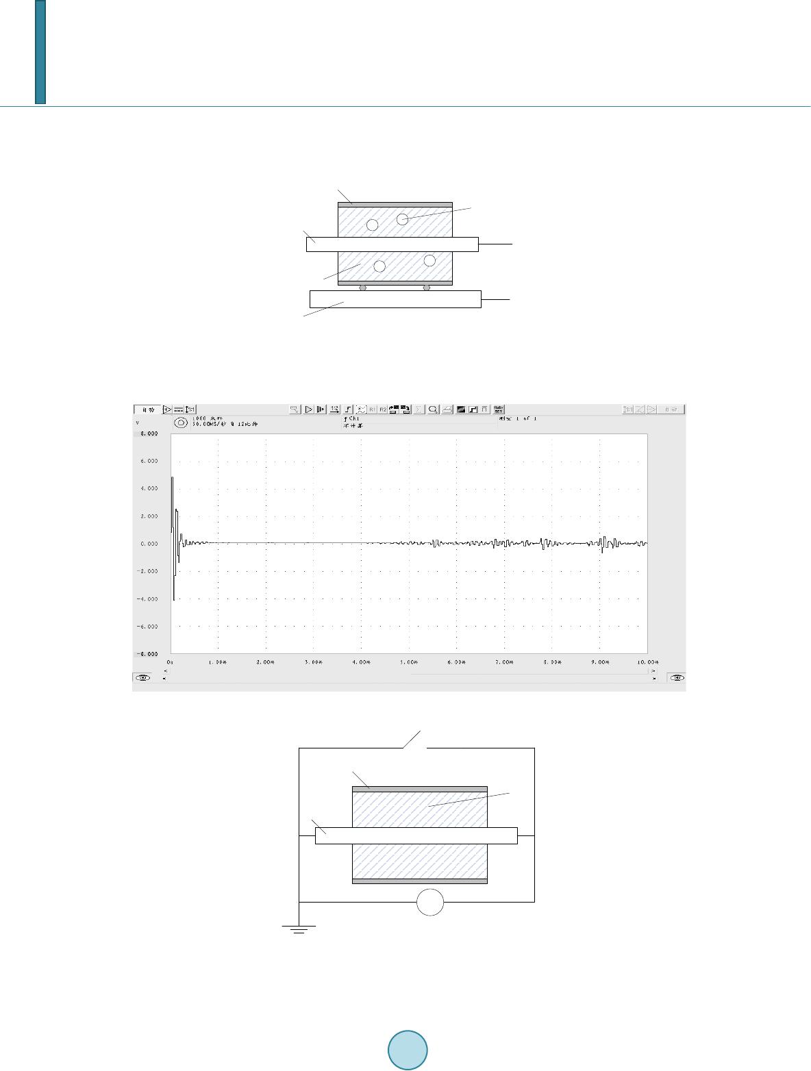
Figure 2 shows the physical model of slot discharge. In this model, copper plate is connec t ed to ground and
copper core is connected to high voltage, and there is an air gap created by low resistance paint layer between
stator bar and the insu lation. With this stru cture, we can simulate the discharge caused by po or contact conditio n
between bar and slot w all.
We regulated the transformer, and observe the phenomenon on different discharge levels. When the power
supply voltage is about 45 kV , the output voltage signal reaches 4 V. The measured amplitude-frequency cha-
racteristic is shown in Figure 3.
We can see from the signal wavefor m that, the initial amplitude is large, but it damps quickly. Then the am-
plitude fluctuates in a small range It is shown in amplitude-frequency wave that the signal is mainly distributed
in the range of 0 - 250 kHz.
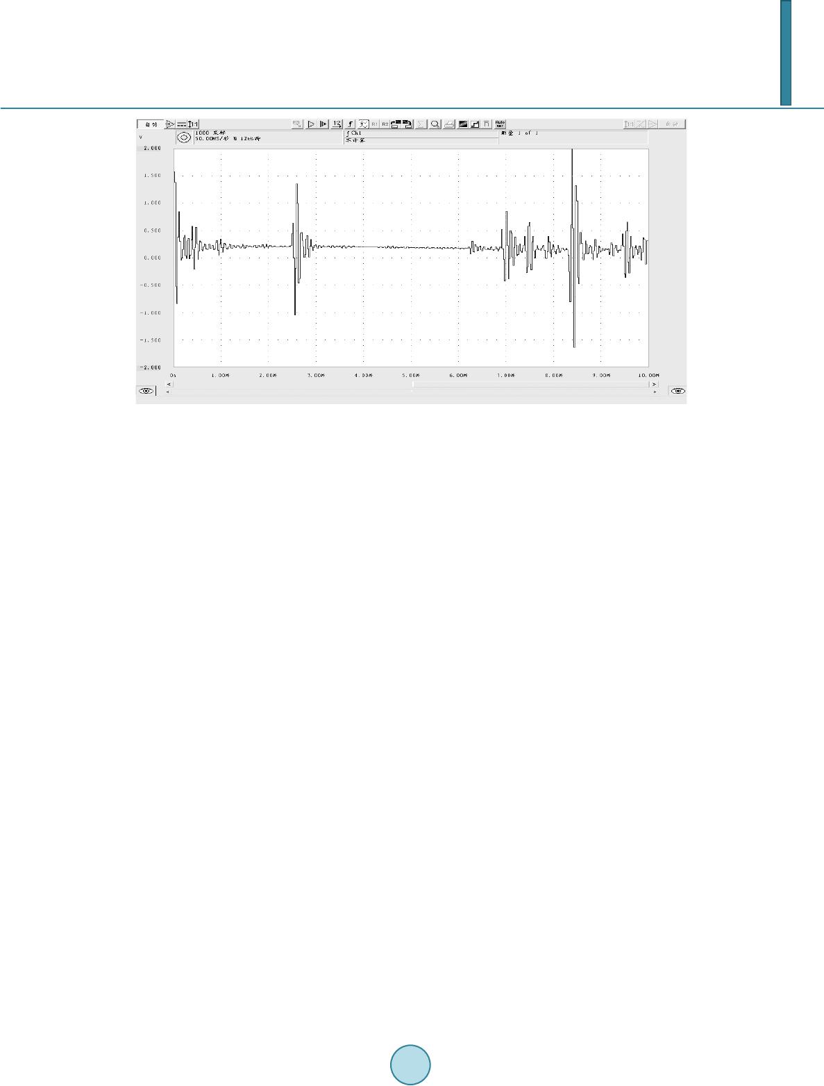
3.2. Arc Discharge Detection
When the motor stator winding is working under mechanical, electricity, heat and other forces, the p lied wire of
stator winding may rupture, which will cause arc discharge. Because of the zero crossing character of power
frequency current, this form of discharge will repeatedly extinguish and rekindle with great energy conversion.
Heat generated in conversion process will accelerate insulation ageing and have significant harm to motor pro-
tection system [4]. Figure 4 shows the physica l model of arc discharge.
Z. Y. Tong et al.
44
We regulated the transformer until the secondary side output voltage reaches about 40 kV. The discharge MF
has been large enoug h, and th e induced voltage signal accordingly has been strong. Th e measu red ampli-
tude-frequency characteristic is shown in Figure 5.
Figure 2. Motor slot discharge model. 1-anti-
halation layer; 2-winding bar; 3-air gap; 4-in-
sulation; 5-stator core; 6-ground terminal; 7-
high voltage terminal.
Figure 3. MF signal of motor slot discharge in frequency domain.
Figure 4. Motor arc discharge model. 1-antihalation
layer; 2-winding bar; 3-insulation; 4-electronic
switch; 5-current source.
3
3
1
2
4
6
5
3
7
3
3
1
3
2
+
-
4
5
Z. Y. Tong et al.
45
Figure 5. MF signal of motor arc discharge in frequency domain.
We can see from the signal waveform that, the amplitude increases in initial period and reaches the first peak
of 1 V. After short durations, the second and the third wave clusters appear. The third wave cluster has the larg-
est amplitude and duration. The characters of arc discharge MF are much different from those of slot discharge
signal. Arc discharge MF lasts longer with much noise. It is shown in amplitude-frequency wave that the signal
is mainly distributed in the range of 0 - 750 kHz, so arc discharge signal has a wider band compared with slot
discharge signal.
4. Conclusions
In this paper, a MF sensor has been developed for motor fault discharge detection. Through applying the sensor
in collecting and analyzing MF signa l of two discharge modes, we proved this sensor feasible in MF detection.
From the analyzing results, we can see that signal of motor slot discharge is strong but the duration is short,
while arc discharge signal has a high peak and the signal lasts longer. The initiation signal stre ngth of arc dis-
charge is weak, and it can increase sharply in a short period . Slot discharge signal continues for a long time w ith
much noise.
Two discharge modes has obvious difference in amplitudes, based on which we can easily d istingu ish the
fault types.
References
[1] Macintyre, S.A. (1991) Magnetic Field Sensor Design, Sensor Review, 11, 7-11
[2] Zhou, Z.J., Cheng, D.F., Wang, J., Zhang, Z.Y. and Liu, X. (2009) Development of Magneto-Dependent Sensor in the
Optical Pumped Magnetometer. Chinese Journal of Sensors and Actuators, 22, 1284-1288
[3] Wilson, A. (1990) High and Low Intensity Slot Discharge. Conference Record of IEEE International Symposium on
Electrical Insulation, 363-366
[4] Hanazawa, T., Almazroui, A. and Egashira, T. (2003) The Distribution of Commutation Sparks in Universal Motors,
Sangyo Oyo Bumonshi, 123, 1546.