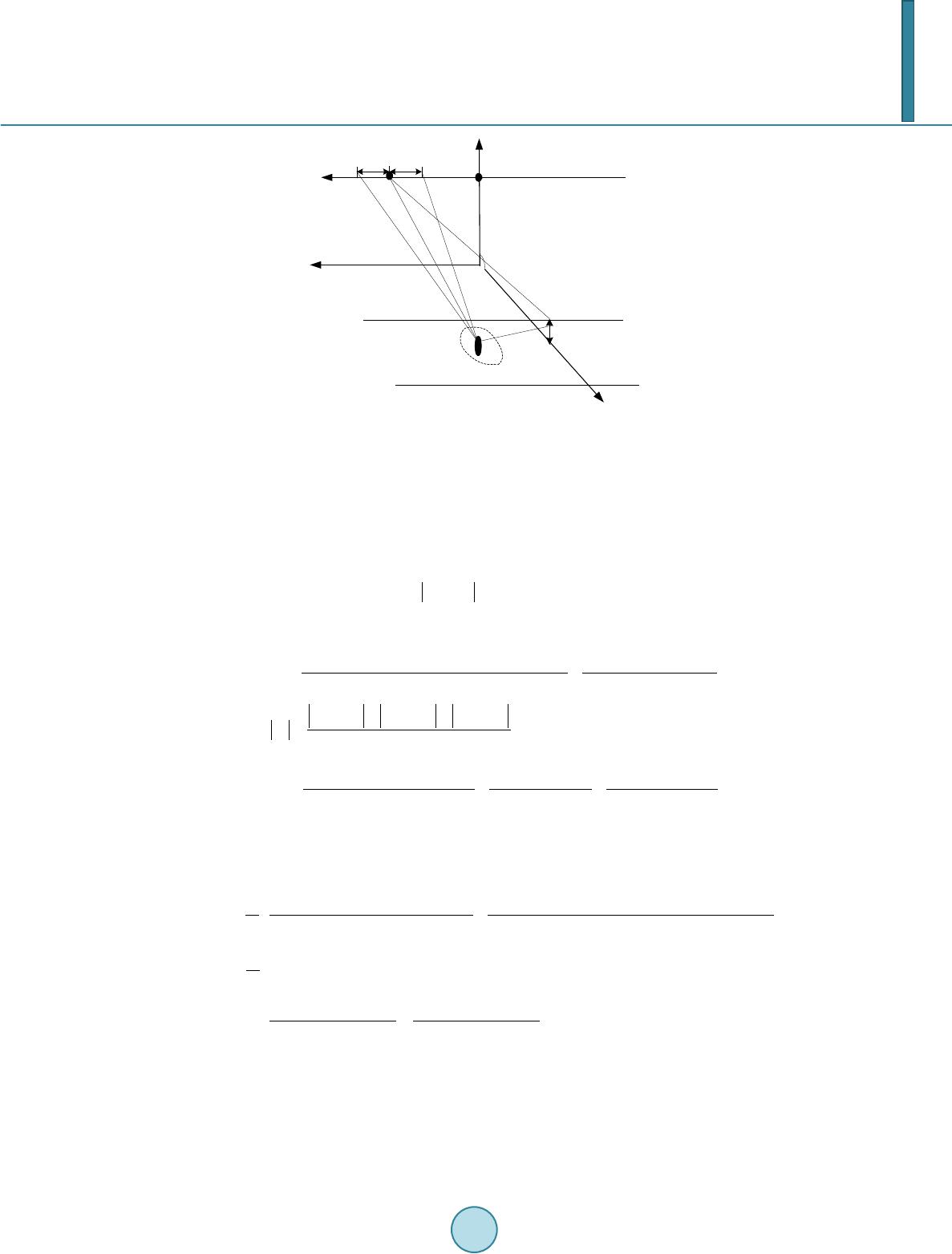
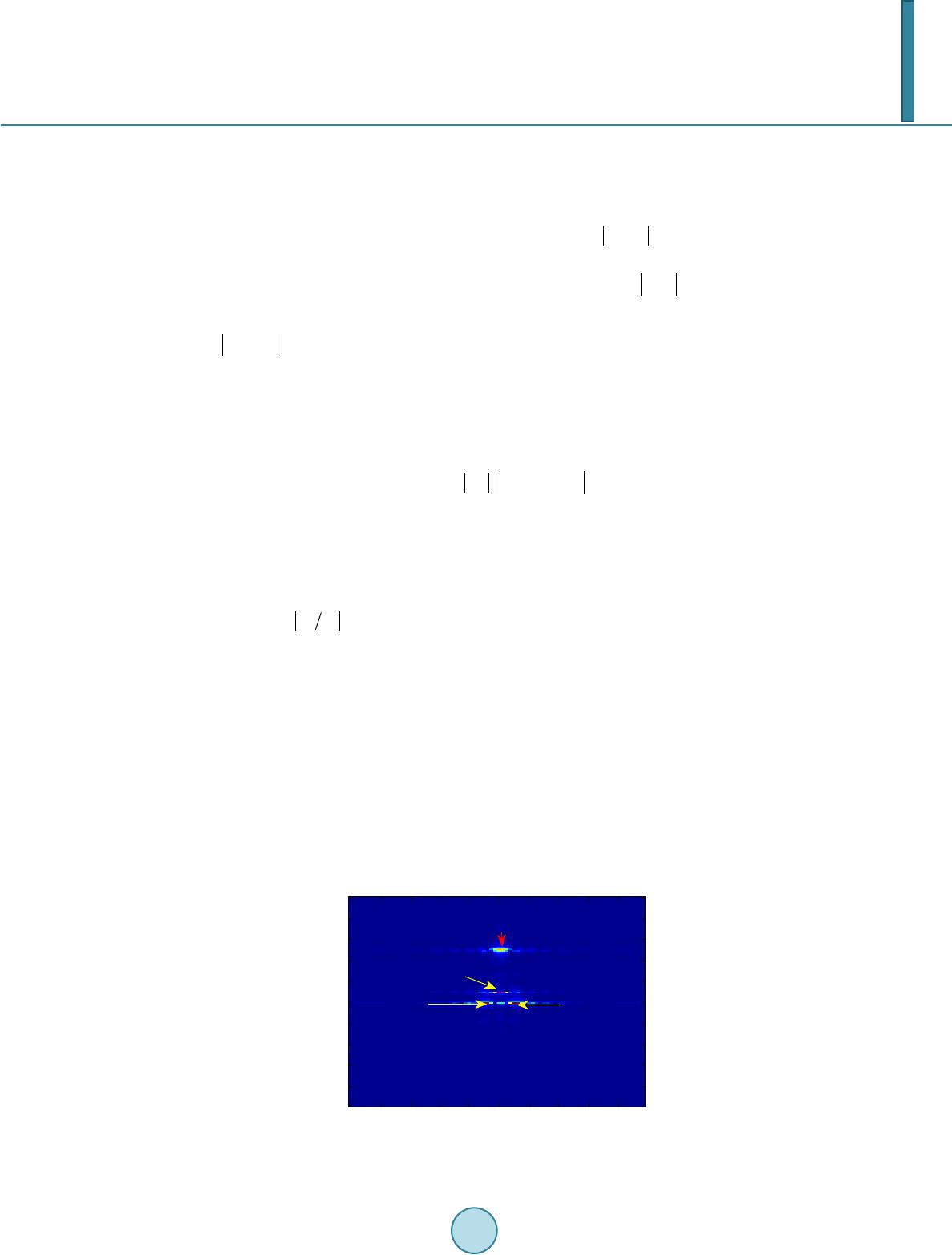
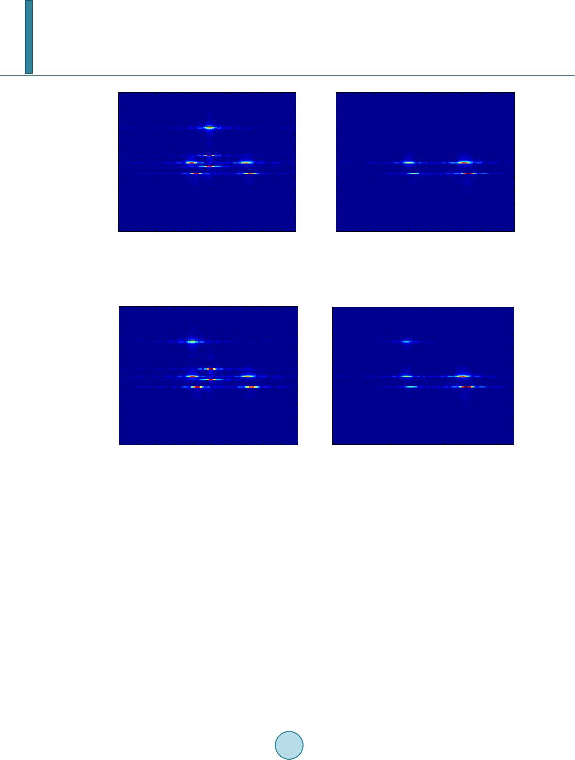
 Journal of Computer and Communications, 2014, 2, 29-35 Published Online May 2014 in SciRes. http://www.scirp.org/journal/jcc http://dx.doi.org/10.4236/jcc.2014.27005 How to cite this paper: Yang, W.H., Chen, Y.G. and Wang, T. (2014) The Intermittent Sampling Motion Scatter Wave Jam- ming against Waveform Agile SAR/GMTI. Journal of Computer and Communications, 2, 29-35. http://dx.doi.org/10.4236/jcc.2014.27005 The Intermittent Sampling Motion Scatter Wave Jamming against Waveform Agile SAR/GMTI Weihong Yang1,2, Yongguang Chen1, Tao Wang1 1School of Electronic Science and Engineering, National University of Defense Technology, Changsha, China 2LYETC, Luoyang, China Email: whyang.2006@163.com Received March 2014 Copyright © 2014 by authors and Scientific Research Publishing Inc. This work is licensed under the Creative Commons Attribution International License (CC BY). http://creativecommons.org/licenses/by/4.0/ Abstract A new method jamming against Waveform Agile SAR/GMTI (Ground Moving Target Indication) is proposed, which is called the intermittent sampling motion scatter wave jamming. This jamming can form multi-false vivid targets scene taking the real moving targets’ all scattering information. The inte r mi tt e nt sampling repeater can also repeat in the waveform agile SAR current pulses. As a clever jamming mode, this jamming may realize electronic counter measure (ECM) against wave- form agile SAR. Detailed discussions about the jamming performance are given. The processing output of the jamming is derived theoreti ca ll y . The superiority of this jamming is analyzed in theory. The theo re ti ca l feasibility and validity are proved by simulation experiments. Keywords SAR, Intermittent Sampling, Waveform Agile, Electronic Counter Measure (ECM), Scatter Wave Jammi ng 1. Introduction Synthetic aperture radar (SAR) is an all weather imaging radar, and SAR Ground Moving Target Indication (GMTI) capability is an important means for strategic reconnaissance and battlefield surveillance systems, which makes it a sever threat to important military targets. Therefore the jamming technology for countering SAR/GMTI has become an important issue in Electronic Counter Measure (ECM) area. Now the active decoy jamming based on DRFM(Digital Radio Frequency Memory) could achieve high processing gain from coherent signals processing in [1]-[6]. But this traditional direct-path repeater decoy jamming against SAR based on re-  W.H. Yang et al. peating the former time SAR pulse is difficult to adapt quickly large pulse width waveform agile SAR in [3]. The frequency-jump burst (FJB) waveform is discussed for SAR-GMTI in [7]. And the new method jamming against Waveform Agile SAR/GMTI is necessary for protecting these important military targets. So a new jamming based motion jammer and the intermittent sampling scatter wave (ISMSC) jamming against waveform agile SAR/GMTI is proposed, called the intermittent sampling Motion scatter wave jamming. The Motion jammer can repeat waveform agile SAR subsection signal in the currently pulse with little delay by the intermittent sampling repeating. It might takes advantage of the intermittent sampling scatter wave jamming against waveform agile SAR GMTI. Firstly, the model of intermittent sampling motion scatter wave jamming is established for waveform agile SAR\GMTI. Secondly, the jamming is imaged in the theory, and characteristics of the jamming imaging are analyzed in the waveform agile SAR\GMTI. In the end, the simulation experiments are shown that the different typical jamming scenarios are imaged. The theory and imaging characteristics of the second part are verified by simulation experiments. 2. The Model of Intermittent Sampling Motion Scatter Wave Jamming The principles of intermittent sampling Motion scatter wave jamming are shown as follows: the waveform agile SAR signal is being high-fidelity intermittent sampled and is modulated by motion jammer projecting to the se- lected area as soon as probably. Then the next section signal is intermittent sampled, Motion modulated and projected to the selected area. The jamming is received as the current pulse target echo being received. The dif- ferent pulses will work as this pulse. Then the intermittent sampling motion scatter wave jamming is formed. As we known, waveform agile SAR system also utilizes the two-dimension LFM (Linear Frequency Modula- tion) pulse signal. LFM signal with unit amplitude can be written as: ( ) ( ) ( ) ( ) ( ) 2 0 ˆ ˆ ,rect()exp j2π( )2 m mprm ststtttT mftt µγ ≡= −⋅++ (1) where is the mth pulse chirp rate, is the chirp rate median, is the mth pulse chirp rate agility modulation, and is carrier frequency, is the fast time (in range), and is the slow time(in azimuth). ( ) 2.1. Intermittent Sampling The intermittent sampling function can be written as in [6]: ( ) ˆˆ ( )rect s n w t p ttnT T δ +∞ =−∞ = ⊗− ∑ (2) Where is the period of sample, is the sample pulse width, “ ” denotes convolution, is Dirac function. Then SAR signal intermittent sampling can be written as: () ()( ) 1ˆˆ ˆ ,, mm s ttsttpt= ⋅ (3) The jammer delay in repeater can be controlled by the jammer in a short interval after receiving the SAR sig- nal. This jamming can also be repeated directly after sampling and modulated, or repeated several times called duplication repeater. Considered efficient of jamming power, usually, the jammer is working in sample storage, or in repeating jamming. If sampling period is determined, the style of intermittent sampling may be identified. 2.2. Motion Modulation Signal sampling interval to the original signal transmitted delay time is usually a constant, so direct repeat- ing jamming delay time is , corresponding the qth repeating delay time in duplication repeating is . The jamming layout is shown as Figure 1, is the SAR platform speed. Because of the fact that the trans- mitting and receiving elements are within a small physical area, the multi-static data may be viewed as mono- static SAR data as the coordinates of the platform are varied in slow time phase centers [6 ].  W.H. Yang et al. Figure 1. The jamming lay out . Three-channel SAR is studied in this paper, the transmit channel is the 2th channel. SAR th channel anten- na coordinate along the track is . The Motion jammer J is in Y axis, which coordinate is . In the selected regions, a scatter unit point P coordinates is . Then the distance of point P jamming signal from the SAR transmitter to the th channel antenna receiver is: ()()()()1,2,3 lmSJm JPmPlm RtRtRtRtl=++ = (4) where is the close distance from the jammer J to SAR phase center S, is the close distance from the point P to SAR phase center S. When , , . is light speed. So we can get Doppler of moving jamming from P and Doppler chirp is: ( )() ()() () () () ( ) ( ) ( ) J J 22 22 22 J PjPxjxPj PyjyPyPjyjPPx jp Px jxPy jyPy jy Px jxPy jyjx jy Px Py jp xxvvy yvvvyvyxv fRR vv vv vv f vv vvvv v vv v R RR λλ λ µλ λλ − −+−−++ ≈+ −+−++ < − +−−+ −+ = ++ (5) is synthetic aperture time. When the jammer is moving as ( )( ) mm cos 2,sin 2 xj jyj j vrftvrft ππ = = , as the scatter point P , the jamming can be seen as Motion, and Doppler of moving jamming from P is simplified as: ( )( ) ( ) ( ) ( ) ( ) ( ) ( ) ( )( ) ( ) mm mm J m cos 2sin2 sin2cos 2 sin 2 tan Pj Pj jPP jp jP jpP jPjP P jp PjPjp PjP x xfty yft rfty xft fRR rft RxRx xRx x Ry RyyRy Ryy ππ ππ λ πθ λ θ − +− + ≈− = + +− − = ≈ +− +− (6) The jammer delay in repeater can be controlled by the jammer in a short interval after receiving the SAR sig- nal. The jamming can be repeated directly after sampling and being modulated once, or repeated several times called duplication repeater. Signal sampling interval relative to the original signal transmitted by the delay time is usually a constant, direct repeating delay time is , corresponding the qth repeating delay time in duplication repeating is .  W.H. Yang et al. 2.3 The Model of Intermittent Sampling Motion Scatter Wave Jamming Signal Then the time correspond to point P jamming repeated directly signal from the SAR transmitter to the receiver is: , this signal of jamming received by the th channel antenna can be written as: ( ) ( ) 11 ˆˆ ˆˆ (,)(,)( (),)( (),2/2) jlmllmlsl mmlsl mm sttAtts tttAs tttlDv ττ =−= −+− (7) where is jamming signal amplitude of the th channel receive corresponding the point P at this time. Neglect the point P scattering diversity, as can be simplified as which is determined by the point P and SAR gain, and is the data channel deviation relative to center channel in the slow time, which is primarily due to the relative physical distance of the th channel to the center channel in the azimuth [6]. SAR is receiving the whole jamming of each scatter point in the selected region surface, which form the whole intermittent sampling Motion scatter wave jamming. So the whole corresponding jamming signal can be written as ( ) 1 ˆ (,); ,,(,) Jl mml q st tAq x y zsttdP ′′ =∑∫∫ (8) where () ˆ(1)( ,,,) ss sm t tqxyzt ττ τ ′′ =+− − is the th repeater jamming fast time, is scatter point integral unit, is jamming signal amplitude of the point P received by the SAR at qth time. 3. Jamming Image The jamming received by SAR is indeed subject to the same signal processing steps of the real target echo, and what may be influenced on the SAR imaging is interpreted as the output of the 2-D LFM the jamming match filtering. So jamming pulse compression is given in the following part. Firstly, repeating directly jamming of point P is matched filtering of fast time in the waveform agility SAR for channel 2, this output is: ( ) () ( )() () ( ) ( ) ( ) ( ) ( ) 0 0 ˆ ˆ (, )(, )p /exp -j2π() rect2()() ˆ ˆ sinc/ sinc() exp -j2π() lm jlmm swJsl mpp s wrprm n RJsl m n y ttsttt TTAfftTmTm nT TtTt Gnf ft ττ τ τ µµγτ τ +∞ =−∞ = ⊗− ′′ ≈+ − ′′ −−+− ≡+ ∑ ∑ (9) where ( )() ()//( )()/( ) smJrmsms rm tnTftn T ττµγ τµγ ′= +−+≈ ++ is the correspond ing fast time after being matched filtering. ( ) It is shown that the jamming matched filtering in fast time generates to the envelope convolution for the trigonometric functions as the target echo. And the intermittent sampling mo- tion scatter wave jamming image focuses very well in fast time. Next jamming in waveform agility SAR is matched filtering in azimuth (slow time), the azimuth match filter- ing function is ( )() 2 rect e am jt amm L ht tT πµ − = ⋅ , so the output can be written as: ( ) ( ) ()( ) ()() () ( ) 21 22 0 2 0 ˆ ˆ (, )(, ) () exp -j2π/ -jπ(2)/ 22 rectexp 2π lmlm am mm RJ J nJP mLm J ytty tth t vt vtx GnffcflD v RR tTjfvtRc = ⊗ − ∝++− ⊗⋅ ∑ (10) If the azimuth mismatch can be ignored, the jamming is similar to a decoy jamming. Transforming from fre- quency domain to time domain, can be written as: ( ) ( ) ()( ) ( ) [ ] 2 rect2sincexp -jπ(2) / lRLmmLmm L mmJ n yGnTttTttTttflDv α µ ′′′ ′ ∝−− −−− ∑ (11) where is synthetic aperture time, ( ) // mlPP JJa tRxRR vfv µ ′ ≈ +− is the corresponding peak in the slow  W.H. Yang et al. time which shows the jamming imaging amplitude peak point in azimuth, and it closes to in the middle of the selection scatter point and jammer location. Of course, when the whole jamming of the selected region surface can be seen false moving targets, the out- put imaging being focused of the jamming can be written as: ( ) ( ) ( ) ( ) ( ) ( ) ( ) /(); ,,sinc ˆ ˆ sinc/( )sinc()()dP Qlwpmm L mm q wpr mp n y TTmAqxyzttTtt nT TmtTmt α µ µγ ττ +∞ = −∞ ′′ ∝− −− ′′ + −−− ∑∫∫ ∑ (12 ) So the intermittent sampling motion scatter wave jamming can be described as follows: When the delay is constant, , , the jamming imaging can be seen vivid targets, the jamming being matched filtering can be focused, and the whole jamming might be focused to form false area vivid targets. When the jamming imaging can be seen as false targets, the performing for GMTI can be written as: ( ) 121222 2322 32 2 2 232322 exp j1 mov J yy yy y ϕ = − = − ′ =∗≈ − I I I II where the moving phase for false target is that is modulated by the jammer. 4. The Simulation Experiment The jamming power is constant, and type jamming is compared against waveform agile SAR and GMTI. SAR carrier frequency is 1 GHz, bandwidth is 100 MHz, modulation frequency agility is random, and chirp rate modulation agility is 0.3; azimuth beam angle is 3.6 degrees. The stationary jammer1 coordinate is , or moving jammer 2 coordinate is . In the selected regions, select area stationary target 1 coordinate at , moving scatter target 2 coordi- nate is and moving scatter target 3 coordinate is , The selected area without any motion and the jammer 2 location is shown as Figure 2. SAR transmit power is 4.5 KW, antenna gain is 35 dB. The jammer power is 10 W. And jammer antenna gain is 12dB, and jammer pulse interval error mismatch is 5dB. And intermittent sampling repeating period is = 0.10 . For the stationary jammer 1, and jamming SAR imaging and GMTI is simulated, and the images are shown as Figure 3(a), Fi gure 3 ( b). These jamming can be focused and form false moving targets as the real moving tar- gets. The residual energy image and GMTI can be seen as theoretical analysis. For the moving jammer 2, and jamming SAR imaging and GMTI is simulated, and the images are shown as Figure 4(a), Figure 4( b) . These jamming also can be focused and form false moving targets as the real moving Figure 2. Selected area and jammer location. A zimuth(m) Range(m) SAR -Imagings -100 -80 -60-40-20 020 40 60 80 9900 9920 9940 9960 9980 10000 10020 10040 10060 10080 The jammer Target 1 Target 2Target 3  W.H. Yang et al. (a) (b) Figure 3. Motion modulation scatter-wave jamming of stationary jammer1 and scene images simulation images. (a) Im- age; (b) Image after GMTI. (a) (b) Figure 4. Motion modulation scatter-wave Jamming of moving jammer 2 and scene images simulation images ( ). (a) Image; (b) GMTI. targets. The residual energy image and GMTI also can be seen as theoretical analysis. When mismatch can be neglected, the figures show that the intermittent sampling motion scatter wave jam- ming focuses very well. Experiment has proved this jamming can form vivid moving targets and be focused as vivid area image, which take the real targets’ all scattering information and does not need to estimate the SAR’s transmitted signal parameters. This jamming technique is effective, and feasible in practice, which has the prominent advantages against multi-channel SAR. The intermittent sampling repeater jamming can adapt to the waveform agile SAR current pulses. The jamming provides a new feasible approach against waveform agile SAR and GMTI. References [1] Ekestorm, R.T. and Christopher, K. (2000) An All-digital Image Synthesizer for Countering Hig h-Resolution Radars. Naval Postgraduate School, Monterey, A93943-5000. [2] Dumper, K., Cooper, P.S., Wons, A.F., Condley, C.J. and Tully, P. (1997) Spaceborne Synthetic Aperture Radar and Noise Jamming . Proc IEE Radar 97. IEEE, Edinburgh, 411-414. [3] Soumekh, M. (2006) SAR-ECCM Using Phase-Perturbed LFM Chirp Signals and DRFM Repeat Jammer Penalization. IEEE TRANS ON AES, 42, 191-205. Azim ut h(m ) Range(m) SAR -Imagings -100 -80 -60 -40 -20 020 40 60 80 9900 9920 9940 9960 9980 10000 10020 10040 10060 10080 Azim ut h(m ) Range(m) SAR-GMTI -100 -80 -60 -40 -20020 4060 80 9900 9920 9940 9960 9980 10000 10020 10040 10060 10080 Azim ut h(m ) Range(m) SAR -Imagings -100 -80 -60 -40-20020 40 6080 9900 9920 9940 9960 9980 10000 10020 10040 10060 10080 Azim ut h(m ) Range(m) SAR-GMTI -100 -80 -60-40 -2002040 6080 9900 9920 9940 9960 9980 10000 10020 10040 10060 10080  W.H. Yang et al. [4] Rosenberg, L. and Gray, D. (2006) Anti-Jamming Techniques for Multichannel SAR Imaging. IE EE Proc. Radar So- nar Navig., 153, 34-242. http://dx.doi.org/10.1049/ip-rsn:20045090 [5] Reigber, A. and Laurent, F.F. (2005) Jamming Suppression in Synthesized SAR Images. IEEE Geoscience and Remote Sensing Letters, 2, 45-50. http://dx.doi.org/10.1109/LGRS.2004.838419 [6] Yang, W. H., Liu, J. and Wan g, T. (2012) Intermittent Sampling Scatter Wave Jamming against SAR. Journal of As- tronautics, 33, 367-373. [7] Mark, E.D. (2011) Common Waveform for Simultaneous DAR and GMTI. IEEE Radar Conference, 282-287.
|