Paper Menu >>
Journal Menu >>
 I. J. Communications, Network and System Sciences, 2008, 2, 105-206 Published Online May 2008 in SciRes (http://www.SRPublishing.org/journal/ijcns/). Copyright © 2008 SciRes. I. J. Communications, Network and System Sciences, 2008, 2, 105-206 Performance Analysis of an AMC System with an Iterative V-BLAST Decoding Algorithm Sangjin RYOO1, Kyunghwan LEE2, Intae HWANG3 1 Department of Electronics Engineering, Chonnam National University, Korea 2 T&M Algorithm Research, Innowireless, Inc., Korea 3 Department of Electronics & Computer Engineering, Chonnam National University, Korea E-mail: 1sjryoo@empal.com, 2signalds@innowireless.co.kr, 3hit@chonnam.ac.kr Abstract In this paper, the iterative Vertical-Bell-lab Layered Space-Time (V-BLAST) decoding algorithm of an Adaptive Modulation and Coding (AMC) system is proposed, and the corresponding MIMO scheme is analyzed. The proposed decoding algorithm adopts iteratively extrinsic information from a Maximum A Posteriori (MAP) decoder as an a priori probability in the two decoding procedures of the V-BLAST scheme of ordering and slicing in an AMC system. Furthermore, the performance of the proposed decoding algorithm is compared with that of a conventional V-BLAST decoding algorithm and a Maximum Likelihood (ML) decoding algorithm in the combined system of an AMC scheme and a V-BLAST scheme. In this analysis, each MIMO schemes are assumed to be parts of the system for performance improvement. Keywords: Iterative V-BLAST Decoding, MAP Decoder, AMC, STD, Turbo Code 1. Introduction To improve the throughput performance together with the development of the MIMO scheme, the AMC scheme has attracted considerable attention as the forerunner of next-generation mobile communication systems [1]. The AMC scheme adapts a coding rate and modulation scheme to the channel condition [2], resulting in improved throughput performance. Consequently, the combination of a MIMO scheme and an AMC scheme can potentially improve the throughput performance. V-BLAST [3,4] was selected as the MIMO multiplexing scheme [5] and the turbo-coding [6] was chosen as the channel coding scheme of the AMC due to the complexity of the aforementioned combined system. The turbo-coding scheme with iterative decoding implies the use of parallel concatenated recursive systematic convolutional codes. Such a scheme is iteratively decoded with a Posteriori Probabilities (APP) algorithms for the constituent codes [7,8]. In addition, the turbo decoding algorithms used with MIMO is currently an area that is actively researched [9,10]. A performance analysis is offered here of AMC systems with several V-BLAST decoding algorithms including the turbo decoding algorithm used with MIMO. For greater performance improvement, the proposed system utilizes a 2×2 MIMO channel using two transmitter antennas and two receiver antennas, a 4-2×2 MIMO channel applying a Selection Transmit Diversity (STD) scheme [11] that selects two antennas from four transmitter antennas, a 4×4 MIMO channel using four transmitter antennas and four receiver antennas, and a 8×8 MIMO channel using eight transmitter antennas and eight receiver antennas. 2. The AMC System with the Proposed Iterative V-BLAST Decoding Algorithm Figure 1 shows the structure of the AMC system used with the proposed iterative V-BLAST decoding algorithm. An AMC system that uses a conventional V- BLAST decoding algorithm combines a V-BLAST scheme with a turbo-coded AMC system. The proposed decoding algorithm of an AMC system differs from the conventional V-BLAST decoding algorithm insofar as the extrinsic information from a MAP decoder is used as an a priori probability in the ordering and slicing decoding procedures of the V-BLAST scheme [12].  120 S.J. RYOO ET AL. Copyright © 2008 SciRes. I. J. Communications, Network and System Sciences, 2008, 2, 105-206 Figure 1. Transmitter-receiver structure of an AMC system with the proposed iterative V-BLAST decoding algorithm This scheme operates iteratively and is defined as the main MAP iteration. Furthermore, whenever the scheme operates internally, iterative decoding of the MAP decoder is performed. This method is defined as sub MAP iteration. For the proposed system, a system equipped with M transmitter antennas and N receiver antennas is considered. It is assumed that each transmission channel is modeled as a flat Rayleigh fading channel. The received signal in the V-BLAST receiver is denoted by X = Hs + n (1) where X=[x1,…,xN]T is the received signal vector, s=[s1,…,sM]T is the transmitted symbol vector, H is the N×M channel matrix, n=[n1,…,nN]T is the noise vector. The superscript T signifies the transpose matrix, and the noise vector, n, is modeled as a complex Gaussian random process. In addition, sm is the 2Q-ary modulated symbol; that is sm=f(d1 m,…,dQ m)∈Φ={φ1,…,φ2Q}, where Q denotes the bit number per symbol, f(·) denotes the symbol modulation function, {dq m}q=1,…,Q represents the q-th information bits that correspond to s m, and {φi}i=1,…,2Q represents the i-th symbol. The proposed slicing algorithm does not make a hard decision with the received signal but makes a decision with the extrinsic information from the MAP decoder [13]. This extrinsic information from the MAP decoder is the log-likelihood function, which can be described as ( ) () , 1 log 0 m q mq m q pd L pd = = = (2) where Lm,q is the extrinsic information that corresponds to dq m [14]. Specifically, {dq m}q=1,…,Q is determined by {Lm,q}q=1,…,Q, respectively. (e.g., if Lm,q is greater than 0, dq m is determined to be 1. Otherwise, dq m is determined to be 0.) The proposed slicing algorithm then performs the quantization operation appropriate to the constellation in use corresponding to {dq m}q=1,…,Q. In a conventional V-BLAST ordering procedure, the decoding order is determined by the SNR of the corresponding layer. The conventional V-BLAST ordering is described as lk = arg m min ||(Hk †)m||2 (3) where k denotes the decoding stage and the superscript † represents the pseudo-inverse matrix. The SNR is a function of the channel power, and the layer with the largest channel power is the first layer that is decoded. A high SNR signifies a low symbol error rate. From this fact, it follows that the maximum SNR criterion can be considered to be a specific version of the minimum symbol error criterion. The proposed ordering algorithm is a function not only of the SNR but also of the extrinsic information. It can be modified accordingly to lk = arg m min Pm(e|Xk, Hk, Lm (i)) (4) where Pm (e|Xk, Hk, Lm (i)) is the symbol error probability of the m-th layer and Lm (i)=[Lm,1 (i),···,Lm,Q (i)]T is the extrinsic information vector of the lk-th layer at the i-th main MAP iteration. The symbol error probability, Pm, can be calculated from Pm(e|Xk, Hk, Lm(i)) = 22 11, 1 2 QQ Q qppq==≠ ∑ ∑P(φq| Lm (i))P(φq→ φp|Xk, Hk, Lm (i)) (5) where φq is the original transmitted symbol, φp is the possible symbol excluding the original transmitted symbol (φq), and P(φq→ φp|Xk, Hk, Lm (i)) is the pair-wise symbol error probability, which can be obtained from P (φq→ φp |Xk, Hk, Lm (i)) = P [ p(φq|ym) < p(φp|ym) ] = P [ log p(φq|ym) < log p(φp|ym)] (6) where y m is the desired symbol that deletes the interference of other symbols after the nulling process of the V-BLAST decoding in the received symbol of the m -th layer, x m . With the assumption that the variance of noise corresponding to the m -th layer is σ m 2 /2, in Eq. (6), the log posteriori function of φ p is described by log p(φp|ym) (7) = log [ p(φp|Lm (i)) p(ym|φp)/p(ym) ] =log p(φp|Lm (i)) + [Re(φ p -φq)(2ym-(φp+φq))*]/2σm 2 where the superscript * signifies a complex conjugate. 3. Simulation Results 3.1. MCS Level and Parameters for Simulation Table 1 shows the Modulation and Coding Scheme 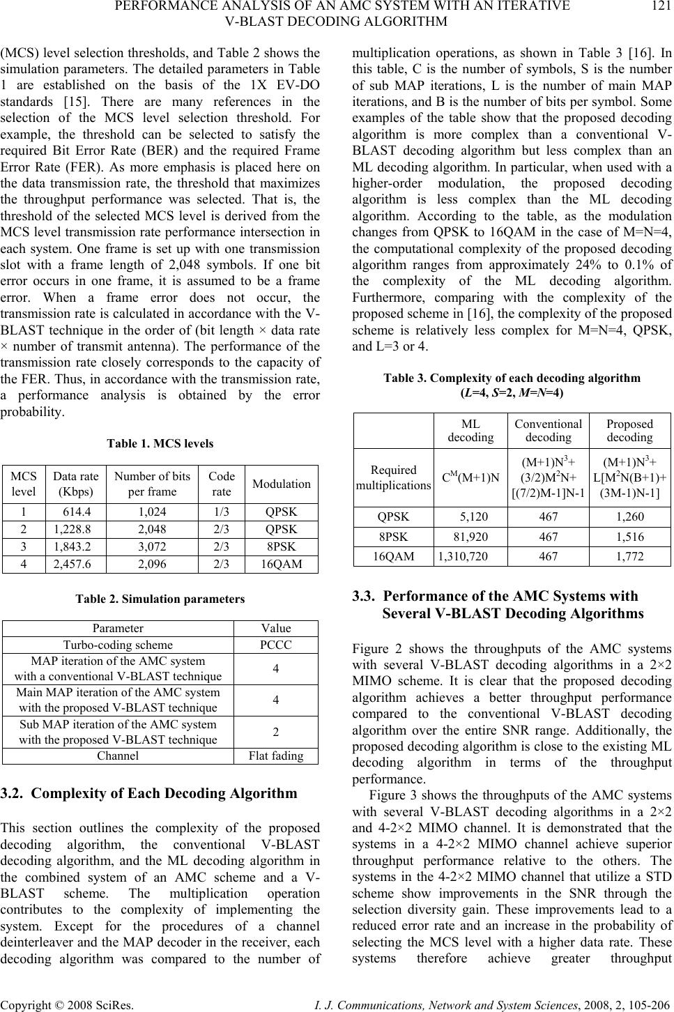 PERFORMANCE ANALYSIS OF AN AMC SYSTEM WITH AN ITERATIVE 121 V-BLAST DECODING ALGORITHM Copyright © 2008 SciRes. I. J. Communications, Network and System Sciences, 2008, 2, 105-206 (MCS) level selection thresholds, and Table 2 shows the simulation parameters. The detailed parameters in Table 1 are established on the basis of the 1X EV-DO standards [15]. There are many references in the selection of the MCS level selection threshold. For example, the threshold can be selected to satisfy the required Bit Error Rate (BER) and the required Frame Error Rate (FER). As more emphasis is placed here on the data transmission rate, the threshold that maximizes the throughput performance was selected. That is, the threshold of the selected MCS level is derived from the MCS level transmission rate performance intersection in each system. One frame is set up with one transmission slot with a frame length of 2,048 symbols. If one bit error occurs in one frame, it is assumed to be a frame error. When a frame error does not occur, the transmission rate is calculated in accordance with the V- BLAST technique in the order of (bit length × data rate × number of transmit antenna). The performance of the transmission rate closely corresponds to the capacity of the FER. Thus, in accordance with the transmission rate, a performance analysis is obtained by the error probability. Table 1. MCS levels MCS level Data rate (Kbps) Number of bits per frame Code rate Modulation 1 614.4 1,024 1/3 QPSK 2 1,228.8 2,048 2/3 QPSK 3 1,843.2 3,072 2/3 8PSK 4 2,457.6 2,096 2/3 16QAM Table 2. Simulation parameters Parameter Value Turbo-coding scheme PCCC MAP iteration of the AMC system with a conventional V-BLAST technique 4 Main MAP iteration of the AMC system with the proposed V-BLAST technique 4 Sub MAP iteration of the AMC system with the proposed V-BLAST technique 2 Channel Flat fading 3.2. Complexity of Each Decoding Algorithm This section outlines the complexity of the proposed decoding algorithm, the conventional V-BLAST decoding algorithm, and the ML decoding algorithm in the combined system of an AMC scheme and a V- BLAST scheme. The multiplication operation contributes to the complexity of implementing the system. Except for the procedures of a channel deinterleaver and the MAP decoder in the receiver, each decoding algorithm was compared to the number of multiplication operations, as shown in Table 3 [16]. In this table, C is the number of symbols, S is the number of sub MAP iterations, L is the number of main MAP iterations, and B is the number of bits per symbol. Some examples of the table show that the proposed decoding algorithm is more complex than a conventional V- BLAST decoding algorithm but less complex than an ML decoding algorithm. In particular, when used with a higher-order modulation, the proposed decoding algorithm is less complex than the ML decoding algorithm. According to the table, as the modulation changes from QPSK to 16QAM in the case of M=N=4, the computational complexity of the proposed decoding algorithm ranges from approximately 24% to 0.1% of the complexity of the ML decoding algorithm. Furthermore, comparing with the complexity of the proposed scheme in [16], the complexity of the proposed scheme is relatively less complex for M=N=4, QPSK, and L=3 or 4. Table 3. Complexity of each decoding algorithm (L=4, S=2, M=N=4) ML decoding Conventional decoding Proposed decoding Required multiplicationsCM(M+1)N (M+1)N3+ (3/2)M2N+ [(7/2)M-1]N-1 (M+1)N3+ L[M2N(B+1)+ (3M-1)N-1] QPSK 5,120 467 1,260 8PSK 81,920 467 1,516 16QAM 1,310,720 467 1,772 3.3. Performance of the AMC Systems with Several V-BLAST Decoding Algorithms Figure 2 shows the throughputs of the AMC systems with several V-BLAST decoding algorithms in a 2×2 MIMO scheme. It is clear that the proposed decoding algorithm achieves a better throughput performance compared to the conventional V-BLAST decoding algorithm over the entire SNR range. Additionally, the proposed decoding algorithm is close to the existing ML decoding algorithm in terms of the throughput performance. Figure 3 shows the throughputs of the AMC systems with several V-BLAST decoding algorithms in a 2×2 and 4-2×2 MIMO channel. It is demonstrated that the systems in a 4-2×2 MIMO channel achieve superior throughput performance relative to the others. The systems in the 4-2×2 MIMO channel that utilize a STD scheme show improvements in the SNR through the selection diversity gain. These improvements lead to a reduced error rate and an increase in the probability of selecting the MCS level with a higher data rate. These systems therefore achieve greater throughput 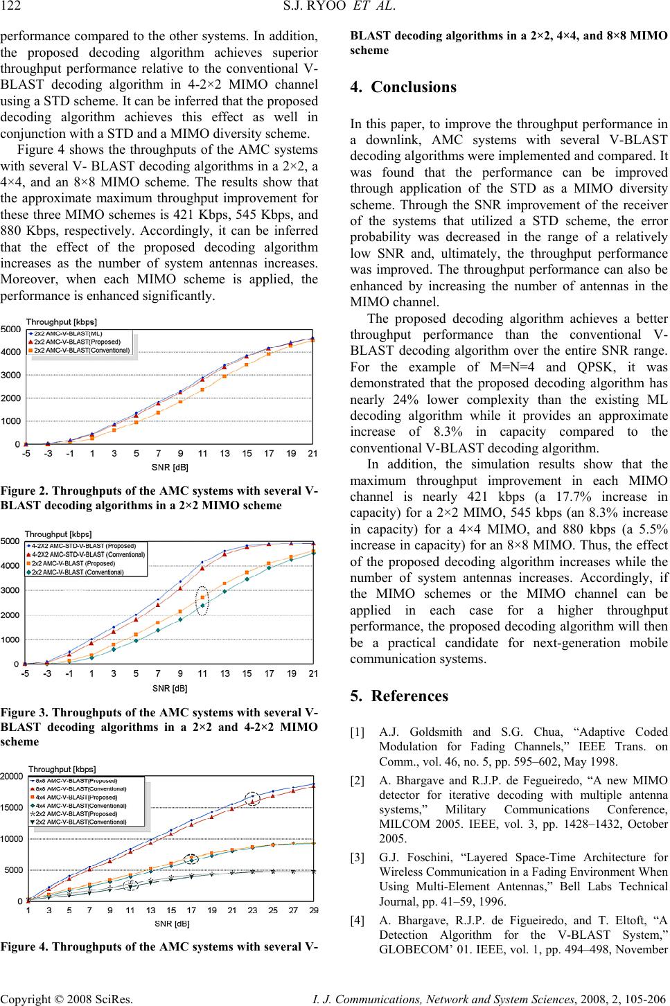 122 S.J. RYOO ET AL. Copyright © 2008 SciRes. I. J. Communications, Network and System Sciences, 2008, 2, 105-206 performance compared to the other systems. In addition, the proposed decoding algorithm achieves superior throughput performance relative to the conventional V- BLAST decoding algorithm in 4-2×2 MIMO channel using a STD scheme. It can be inferred that the proposed decoding algorithm achieves this effect as well in conjunction with a STD and a MIMO diversity scheme. Figure 4 shows the throughputs of the AMC systems with several V- BLAST decoding algorithms in a 2×2, a 4×4, and an 8×8 MIMO scheme. The results show that the approximate maximum throughput improvement for these three MIMO schemes is 421 Kbps, 545 Kbps, and 880 Kbps, respectively. Accordingly, it can be inferred that the effect of the proposed decoding algorithm increases as the number of system antennas increases. Moreover, when each MIMO scheme is applied, the performance is enhanced significantly. Figure 2. Throughputs of the AMC systems with several V- BLAST decoding algorithms in a 2×2 MIMO scheme Figure 3. Throughputs of the AMC systems with several V- BLAST decoding algorithms in a 2×2 and 4-2×2 MIMO scheme Figure 4. Throughputs of the AMC systems with several V- BLAST decoding algorithms in a 2×2, 4×4, and 8×8 MIMO scheme 4. Conclusions In this paper, to improve the throughput performance in a downlink, AMC systems with several V-BLAST decoding algorithms were implemented and compared. It was found that the performance can be improved through application of the STD as a MIMO diversity scheme. Through the SNR improvement of the receiver of the systems that utilized a STD scheme, the error probability was decreased in the range of a relatively low SNR and, ultimately, the throughput performance was improved. The throughput performance can also be enhanced by increasing the number of antennas in the MIMO channel. The proposed decoding algorithm achieves a better throughput performance than the conventional V- BLAST decoding algorithm over the entire SNR range. For the example of M=N=4 and QPSK, it was demonstrated that the proposed decoding algorithm has nearly 24% lower complexity than the existing ML decoding algorithm while it provides an approximate increase of 8.3% in capacity compared to the conventional V-BLAST decoding algorithm. In addition, the simulation results show that the maximum throughput improvement in each MIMO channel is nearly 421 kbps (a 17.7% increase in capacity) for a 2×2 MIMO, 545 kbps (an 8.3% increase in capacity) for a 4×4 MIMO, and 880 kbps (a 5.5% increase in capacity) for an 8×8 MIMO. Thus, the effect of the proposed decoding algorithm increases while the number of system antennas increases. Accordingly, if the MIMO schemes or the MIMO channel can be applied in each case for a higher throughput performance, the proposed decoding algorithm will then be a practical candidate for next-generation mobile communication systems. 5. References [1] A.J. Goldsmith and S.G. Chua, “Adaptive Coded Modulation for Fading Channels,” IEEE Trans. on Comm., vol. 46, no. 5, pp. 595–602, May 1998. [2] A. Bhargave and R.J.P. de Fegueiredo, “A new MIMO detector for iterative decoding with multiple antenna systems,” Military Communications Conference, MILCOM 2005. IEEE, vol. 3, pp. 1428–1432, October 2005. [3] G.J. Foschini, “Layered Space-Time Architecture for Wireless Communication in a Fading Environment When Using Multi-Element Antennas,” Bell Labs Technical Journal, pp. 41–59, 1996. [4] A. Bhargave, R.J.P. de Figueiredo, and T. Eltoft, “A Detection Algorithm for the V-BLAST System,” GLOBECOM’ 01. IEEE, vol. 1, pp. 494–498, November 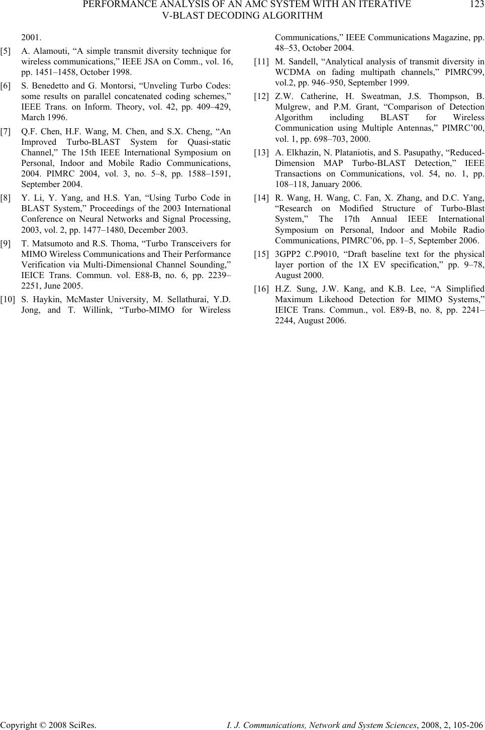 PERFORMANCE ANALYSIS OF AN AMC SYSTEM WITH AN ITERATIVE 123 V-BLAST DECODING ALGORITHM Copyright © 2008 SciRes. I. J. Communications, Network and System Sciences, 2008, 2, 105-206 2001. [5] A. Alamouti, “A simple transmit diversity technique for wireless communications,” IEEE JSA on Comm., vol. 16, pp. 1451–1458, October 1998. [6] S. Benedetto and G. Montorsi, “Unveling Turbo Codes: some results on parallel concatenated coding schemes,” IEEE Trans. on Inform. Theory, vol. 42, pp. 409–429, March 1996. [7] Q.F. Chen, H.F. Wang, M. Chen, and S.X. Cheng, “An Improved Turbo-BLAST System for Quasi-static Channel,” The 15th IEEE International Symposium on Personal, Indoor and Mobile Radio Communications, 2004. PIMRC 2004, vol. 3, no. 5–8, pp. 1588–1591, September 2004. [8] Y. Li, Y. Yang, and H.S. Yan, “Using Turbo Code in BLAST System,” Proceedings of the 2003 International Conference on Neural Networks and Signal Processing, 2003, vol. 2, pp. 1477–1480, December 2003. [9] T. Matsumoto and R.S. Thoma, “Turbo Transceivers for MIMO Wireless Communications and Their Performance Verification via Multi-Dimensional Channel Sounding,” IEICE Trans. Commun. vol. E88-B, no. 6, pp. 2239– 2251, June 2005. [10] S. Haykin, McMaster University, M. Sellathurai, Y.D. Jong, and T. Willink, “Turbo-MIMO for Wireless Communications,” IEEE Communications Magazine, pp. 48–53, October 2004. [11] M. Sandell, “Analytical analysis of transmit diversity in WCDMA on fading multipath channels,” PIMRC99, vol.2, pp. 946–950, September 1999. [12] Z.W. Catherine, H. Sweatman, J.S. Thompson, B. Mulgrew, and P.M. Grant, “Comparison of Detection Algorithm including BLAST for Wireless Communication using Multiple Antennas,” PIMRC’00, vol. 1, pp. 698–703, 2000. [13] A. Elkhazin, N. Plataniotis, and S. Pasupathy, “Reduced- Dimension MAP Turbo-BLAST Detection,” IEEE Transactions on Communications, vol. 54, no. 1, pp. 108–118, January 2006. [14] R. Wang, H. Wang, C. Fan, X. Zhang, and D.C. Yang, “Research on Modified Structure of Turbo-Blast System,” The 17th Annual IEEE International Symposium on Personal, Indoor and Mobile Radio Communications, PIMRC’06, pp. 1–5, September 2006. [15] 3GPP2 C.P9010, “Draft baseline text for the physical layer portion of the 1X EV specification,” pp. 9–78, August 2000. [16] H.Z. Sung, J.W. Kang, and K.B. Lee, “A Simplified Maximum Likehood Detection for MIMO Systems,” IEICE Trans. Commun., vol. E89-B, no. 8, pp. 2241– 2244, August 2006. |