Journal of Applied Mathematics and Physics, 2014, 2, 384-390
Published Online May 2014 in SciRes. http://www.scirp.org/journal/jamp
http://dx.doi.org/10.4236/jamp.2014.26045
How to cite this paper: Chen, Y.-W. and Tsai, G.-C. (2014) The Crack of Turbine Blade Effect on the Dynamic Behavior of
Turbine. Journal of Applied Mathematics and Physics, 2, 384-390. http://dx.doi.org/10.4236/jamp.2014.26045
The Crack of Turbine Blade Effect on the
Dynamic Behavior of Turbine
Yen-Wei Chen, Gwo-Chung Tsai*
Department of Mechanical and Electro-Mechanical Engineering National Ilan University, ILan, Taiwan
Email: *sm910902 @yaho o.com.tw, *gct sai@niu.edu .tw
Received January 2014
Abstract
In this report, the finite element method is applied to study the crack effect on the dynamic beha-
vior of the turbine blade. There are four subjects reported in this paper. The first subject de-
scribes the material properties, the visual observation of the blade crack, the geometric dimen-
sional measurement of the turbine blade. The second part will present the finite element models
included single blade and a group of 6 blades. The third section will build up the full model of 60
blades. The full model will have four different types: the first type that has no crack in the blade
root named “No crack”, the second type has the 126 mm2 crack area in the blade root and it is
named “1 Line crack”, the 3rd type has 364 mm2 crack area in the crack root (named 2 Lines
Crack), and the fourth type has 598 mm2 crack area in the root (named 3 Lines Crack). The loca-
tion of crack area is modeled by applying the spring elements. The vibration frequencies for single
blade and a group of 6 blades are higher without the crack in the blade root. For full model of 60
blades, the vibration frequencies are lower with the crack area in the blade root. When the crack
area becomes bigger, the lower frequencies of the full blade system are observed.
Keywords
Crack, Turbine, Dynamic Behavior
1. Introduction
In this report, the finite element method is applied in the study of the dynamic behavior of the turbine blade. The
finite element method is a popular and powerful method to solve the complex structural problems. The method
is to create lots of small sections to represent the real body and small section is called “element”. Any structure
can be represented by a finite number of elements, and each element may have their shape function to conduct
their static and dynamic behavior. After the structure is meshed to be a finite number of elements, the structures
will become a finite element model. Application of mechanical properties, boundary conditions, and external
force conditions to the model, the static and dynamic behavior of the structure can be observed after the analysis
is performed (1). The structural behavior can be expressed by the deformation values, stresses and strains. All of
these values can give the engineers the real quantities, and combined these quantities with the yielding criteria or
failure criteria; the reliability of the structures can be obtained. In the previous study, most of the researches
*
Corresponding author.
Y.-W. Chen, G.-C. Tsai
385
concerned on finding the cause of the crack in the blade, and few of papers discussed the dynamic behavior of
the blade systems that have subjected to the cracks in the structure. Therefore, the study about the dynamic be-
havior of the blade with the crack in the root is performed in this report.
The material properties of the blade are obtained through the chemical and mechanical tests. The geometry of
the blade is obtained by applying 3-D measurement system to measure the discarded blade. The measured data
combined with the Auto-CAD computer program to get the exact geometric dimensions. Then apply ANSYS
Pre-processor to read all of the geometric dimensions and create the finite element model of a single blade. The
free -free vibration analysis is applied to obtain the nature frequencies of single blade and compared with the test
results. After these, the finite element model of a group of blades and full system of turbine blade are generated
to investigate the dynamic behavior of blades.
Most of the researches about the dynamic behavior of the turbine blade are concentrated on using one-di-
mensional or two-dimensional models. Therefore, Euler beam was commonly applied in one-dimensional simu-
lation, a few of studies can really consider 3-dimensional turbine blade model. The major reasons came from the
complicated blade geometric dimensions and it is hard to describe by using the mathematical equations. The
other reasons are that the real 3-dimensional geometric data of turbine blade are difficult to get. Therefore, most
of the researches only select the cantilever beam to simulate the rotating dynamic behavior of the turbine blade
and its system (2). In this report, for compensating these gaps, using 3-D type elements creates all of turbine
blade models.
Some turbine blades may have defects due to the manufacture processing and the cracks may have observed
at some locations of high stress area due to the long operation time of turbine blades. The strength and fatigue
life of turbine blades will be reduced as the crack exited at some locations. If the cracks existed at some loca-
tions of turbine blades, the local modes may appear when the turbine blade is in the dynamic status. The local
modes may cause the failure of the whole system; some researches had done these investigations, such as Rizso
(1990), Chen and Chen (1980), and Gwo-ching Tsai (1996). Most of studies proposed by Ben Diksen (1987),
Hodge (1982), Pierre and Dowell (1987), and Wei and Pierre (1988), they selected the beam model to simulate
the vibration behavior of the full blade system, even if the newest researches published by Huang and Kuang [1],
they still used beam model. They all get the same conclusions: the vibration amplitude of the beam near the
crack area is going up and this may cause the failure of the system. But all of these researches didn’t mention the
other effects on the dynamic behavior of full blade systems due to the crack existed in the model. For under-
standing more about the crack effect on the dynamic behavior of the full blade system and the Campbell Dia-
gram, the detailed analyses are performed in this paper. Some papers ([2]-[4]) had pointed out that the full
three -dimensional finite element analyses can really understand the dynamic behavior of the full system because
3-D finite element model can completely simulate the complicated shape and geometry of the blade, shroud, te-
non, blade root, and disk. The 3-D finite element method is approved to be useful in the generation and analyses
of the full system of turbine blade.
2. Free-Free Vibration of Single Blade
The geometric data of a single blade is obtained from a real blade. The material of blade is AISI 403 stainless,
the mechanical properties are the following:
Tensile strength = 786.48 MPa, Yielding stress = 666MPa, Elongation rate = 10.19010.
Youngs modulus = 221,599 MPa. In this report, the unit is mm, therefore, the above material properties can
be transformed to be: Yo ungs modulus = 2.216 E8kg-mm/s 2/mm2, Density = 7.7E−6 kg/mm, Poissons ratio =
0.27.
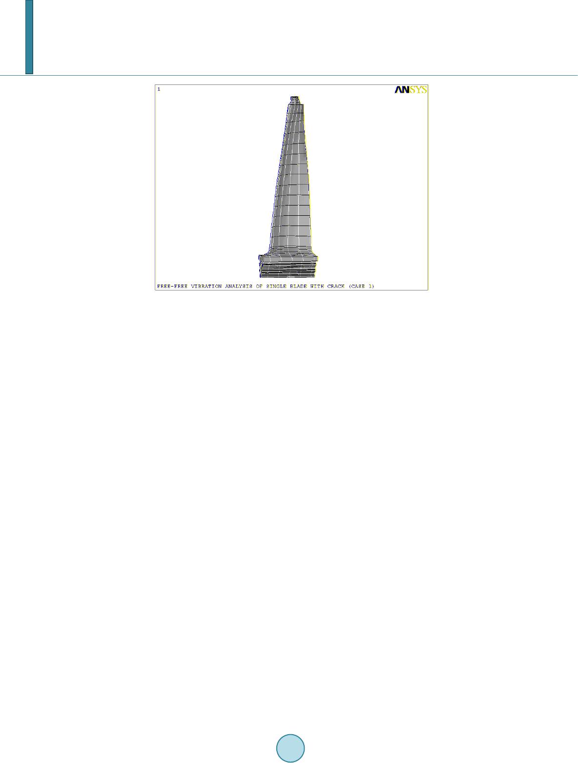
The finite element model of a single blade is shown in Figure 1. The model has 777 solid45 elements and
1395 nodes. Basically there have three methods to simulate the crack in the blade: the first method is to create
two separate nodes at the same location along the crack surface, this method has no any restrictions between two
neighboring nodes, if the nodes are in separation condition this model can reasonably describe their behavior,
but the solution may make some mistakes as the nodes penetration into the opposite side of body which can not
match with the real conditions. The second method is to apply combination element to simulate the crack. The
combination element basically is spring plus damper. The crack is being simulated by using spring element is
popular and the results are exactly matched with the test data. The third method is that the contact element is ap-
plied to replace the crack. But the contact element is a nonlinear analytical method and it is only available in the
static analysis. The nonlinear characteristic of contact element is not available as the dynamic condition is sus-
Y.-W. Chen, G.-C. Tsai
386
Fig ure 1. Finite element model of a single blade.
tained with. It may have reasonable results as the 2nd method is applied. Therefore, in this report, the 2nd me-
thod is that the spring element is applied in the crack area, and the damper effect is not considered here.
The results of free-free vibration analysis for a single blade are shown in Table 1 that the frequencies ob-
tained from FEM are completely matched with those of experimental data. The frequencies of a single blade
with 2 Lines crack area in the root and the spring element with different spring constants are shown in Table 2.
In Table 2, even if the spring constant changes 100 scales, but the frequencies of the blade has not much
changed. The spring constants are determined from Hertz Contact law. For simplification, the spring constants
of 2.216E7 kg/s2/mm are applied in the following analysis. Comparison for Table 1 and Table 2, it can be found
that the first mode frequencies of the single blade with and without crack are almost the same. The frequencies
of the blade with and without crack for higher mode have only a little difference such as the eleventh mode; the
frequencies of a single blade without crack are 4121.9 Hz and with crack are going down to be 4062.3 Hz (for K =
2.216E7 kg/s2/mm) that the in-significant difference (only 1.45% difference) can be observed. From these re-
sults, the crack size didn’t effect on the vibration frequencies of a single blade.
3. Vibration Analysis of a Group of 6 Blades
In this section, the turbine blade of a group of 6 blades will be analyzed. These 6 blades are connected together
through using the shroud that will be hold by blade tenon. From the research results obtained in reference 3 - 6,
the blade root is not completely contacted with the disk. Only the top part of each ditch of the blade is connected
with the disk. The lower part of the blade root is away from the disk. Also, in a certain location of blade plat-
form, a pin was used to make the blade root connect with the disk and prevent the blade slicing in the shaft di-
rection. The finite element model for a group of 6 blades is plotted in Figure 2. The crack is also selected to
have the same location mentioned in ref. 3 - 5. The initial crack is found in this location for some of these tur-
bine blades. For the other design of blade, the crack location may have changed and must be checked out. For
simplifying the analytical job, the crack is assumed to be existed in all of 6 blades. The crack area in the blade
root are selected to be three sizes: 1-Line crack (the crack area with the length of 13.9 mm and width of 9 mm),
2-Lines crack (the crack area with the length of 25.9 mm, and the width of 13.9 mm), 3-Lines crack (the crack
area with the length of 42.7 mm and the width of 13.9 mm). The vibration analyses will consider different rotat-
ing speed, which is 0 rpm, 2000 rpm, 4000 rpm, 5000 rpm and 5800 rpm, these values are also corresponding to
the real operation rotating speed of turbine blade. The bottom of the disk, which supposed to connect with the
major shaft, is assumed to be fixed. The results for a group of 6 blades with different rotating speed are shown in
Table 3. From Table 3, the frequencies are increasing as the rotating speed is increased because the structural
stiffness is increased as the rotating speed is up. It is also shown that the model frequencies are going down, as
the crack area is becoming bigger which the structure obviously becomes softe ned.
Y.-W. Chen, G.-C. Tsai
387
Figure 2. Finite element model of a group of 6 blades.
Table 1. Natural frequencies of a single blade (No crack).
No crack
Mode Frequency (test) Frequency (analysis)
7 873 846.68
8 1910 1835.3
9 2410- 2383.0
Table 2. Natural frequencies of a single blade (2 lines crack).
K = 2.216 × 10⁸ Kg-mm/s2/mm K = 2.216 × 10⁷ Kg-mm/s2/mm K = 2.216 × 10⁶ Kg-mm/s2/mm
Mode Frequency (Hz) Frequency (Hz) Frequency (Hz)
7 846.12 846.07 846.05
8 1829.7 1829.7 1829.6
9 2365 2362.6 2358.8
10 3529.1 3522.3 3493.2
11 4069.8 4062.3 4025.5
Table 3. Vibration frequencies of a group of 6 blades (No crack).
ω = 0 rpm ω = 2000 rpm ω = 4000 rpm ω = 5000 rpm ω = 5800 rpm
Mode Frequency (Hz) Frequency (Hz) Frequency (Hz) Frequency (Hz) Frequency (Hz)
1 339.48 344.51 359.15 367.70 379.53
2 662.92 664.88 670.67 673.92 678.94
3 761.91 764.52 772.25 777.93 783.32
4 1218.4 1221.5 1230.5 1237.0 1242.9
5 1290.6 1296.3 1313.1 1325.6 1337.5
6 1322.0 1327.5 1343.7 1355.7 1367.0
7 1364.2 1369.9 1386.6 1399.0 1410.7
8 1417.6 1422.9 1438.1 144835 1457.4
9 1435.1 1440.6 1456.7 1468.5 1479.3
10 1463.9 1465.9 1472.4 1478.5 1485.4
Y.-W. Chen, G.-C. Tsai
388
4. The Vibration Analysis of the Whole Circle of Blade
From a group of 6 blades finite element model, using ANSYS pre-processing can create the full cyclic turbine
blade system. The 60 blades system is plotted in Figure 3 which has 59930 nodes, and 37,162 elements. The
spring constant for the crack in the full model is still set to be 2.216 × 10⁷ kg-s2/mm. The effect of blade with
cracks and without crack on the Campbell Diagram is shown in Fig ure s 4-7. Getting fifty vibration frequencies
from the mode analyses plots the Campbell Diagram. Full model is used to be analyzed by selecting the follow-
ing rotating speed included 0 rpm, 500 rpm, 1500 rpm, 2500 rpm, 3500 rpm, 4500 rpm, and 6000 rpm. From
Figures 4-7, the frequencies have 6 different ranges for each rotating speed. Therefore, the six curves can be
observed through 0 rpm to 6000 rpm. The natural vibration curves generally didn’t cross through the frequencies
curves. If the natural vibration curves crossed with the frequencies curves, the frequencies at the cross point may
cause the resonant problems and will result in the higher vibrating amplitude of the structure. When the turbine
blade starts to operate, the rotating speed must be increased from 0 rpm to 5800 rpm. Therefore, the system
should pass the reasonant frequencies, but it is ok if the system didn’t stay on near the resonant frequencies.
From F igur es 4-7, the frequencies variation is a linear function of the rotation speed. If the crack existed in the
blade system, the frequencies may have some changing. For example, the frequencies for mode 31 to 41 are ob-
served in 2-Lines creak model are not the same as found in the other three models. The fifth vibration curves for
Figure 3. Finite element model of full system.
Figure 4. Campbell diagram of whole system of blades (No crack).
CAMPBELL DIAGRAM
0
500
1000
1500
0500 1000 1500 20002500 30003500 40004500 50005500 6000
Speed-R PM
Blade Frequency-CP
Y.-W. Chen, G.-C. Tsai
389
Figure 5. Campbell diagram (1 line crack).
Figure 6. Campbell diagram (2 lines crack).
Figure 7. Campbell diagram of whole system of blades (3 lines crack).
CAMPBELL DIAGRAM
Speed-R PM
Blade Frequency-CP
CAMPBELL DIAGRAM
0
500
1000
1500
05001000 1500 20002500 3000 35004000 4500 50005500 6000
Speed-R PM
Blade F requency-CP
CAMPBELL DIAGRAM
0
500
1000
1500
05001000 1500 20002500 3000 35004000 4500 50005500 6000
Speed-R PM
Blade F requency-CP
Y.-W. Chen, G.-C. Tsai
390
2-Lines crack model in the Campbell Diagram is going down as the rotating speed is approached to 6000 rpm. If
any abrupt change in the Campbell Diagram is obtained, engineer must be careful of the phenomena because the
operating conditions must be corrected during the turbine blades are operating in these conditions.
5. Conclusions and Discussions
From the above analyses, the following conclusions can be obtained:
For a single blade and a group of 6 blades:
1) The stiffness of a single blade with the crack will be going down as the crack area become bigger and bigger,
and the vibration frequencies become lower as the creak area become bigger, but the difference for a single
blade with and without the crack are not significant.
2) The vibration frequencies of a group of 6 blades will be affected by the rotating speed and crack area in the
blade root. The frequencies are going up as the rotating speed is increasing and going down as the crack area
is becoming bigger. These two factors effect on the vibration behavior of the group of turbine blade must be
carefully considered.
For full cyclic system of turbine blades with and without the crack:
1) The vibration frequencies are going down as the blade root crack area become larger, which are the same as
that observed from a single blade and a group of 6 blades.
2) Due to the less stiffness for the turbine blade with the crack, the mode shape of the full system of turbine had
changed. The deformation occurred in the disk for the turbine blade system without the crack will be shifted
to the turbine blade. It means that the nodal diameters appeared in the disk as the turbine blade without the
crack and those will be observed in the blade as the turbine blade root with the crack. The phenomena be-
come clear as the turbine blade root has a 3 Lines crack.
3) Basically, the mode shapes are very similar for the full turbine blade system without crack and with one Line
crack. The mode shapes have much different for the full blade system with one-Line crack and two line
crack. But the mode shapes are also very similar between the full blade system of 2-Lines crack and 3-Linse
crack. The major reason for these is because the crack area effect on the vibration behavior of the full blade
system. The crack area of the 1-Line crack turbine system is similar, so the dynamic behaviors foe 1-line
crack turbine blade system are not much different from the turbine blade system without the crack. The crack
area for 2-Lines crack and 3-Lines crack of the turbine blade system have no significant difference due to the
sizes of crack area are closed each other.
From the about discussions, some suggestions are made in the following:
1) Due to the crack area having a significant effect on the vibration behavior, the characteristics in the crack
area must be studied in advance. The results in this report assumed that the crack has the stiffness, so it can
be modeled by using the spring element only. But in fact the damping effect in the crack may have a signifi-
cant effect on the dynamic behavior, it is suggested that the damper element must be included in the future
work.
2) For harmonic analysis, the applied force must be included in the analyses to find the resonant response at the
resonant frequencies. The more studies must be performed, the more information can be obtained to under-
stand the force response effect on the full blade system with and without crack. The stress distribution may
have different d istrib ution s due to the crack existed in the full blade system.
Acknowledgements
The researches are really thanked to National Science Council financial support. The plan number is NSC 102-
3113-P-002-020.
References
[1] Huang, R.W. and Kuang, J.H. (1997) The Mode Localization in a Grouped Rotation Blade-Disk with a Cracked Blade.
Proceedings of the 23rd National Conference on Theoretical and Applied Mechanics, Taiwan, 55-62.
[2] Tsai, G.C. The Natural Frequencies and Mode Shape of Composite Laminate with Multiple.
[3] De-laminations (1996 ) Proceeding of the Basic Mechanics Conference at Military University.
[4] Tsai, G.C. (1996) Effect of De-lamination on the Natural Frequencies and Mode Shape of Composite Laminate.
ANSYS User Conference, Oct., 19 9 6.