 Journal of Applied Mathematics and Physics, 2014, 2, 323-334 Published Online May 2014 in SciRes. http://www.scirp.org/journal/jamp http://dx.doi.org/10.4236/jamp.2014.26039 How to cite this paper: Yao, E.R., Wang, H.R., Pan, L., Wang, X.B. and Woding, R.H. (2014) Vertical Water-Entry of Bul- let-Shaped Projectiles. Journal of Applied Mathematics and Physics, 2, 323-334. http://dx.doi.org/10.4236/jamp.2014.26039 Vertical Water-Entry of Bullet-Shaped Projectiles Erren Yao1*, Huanran Wang1, Long Pan1, Xinbing Wang2, Rihai Woding3 1School of Energy and Power Engineering, Xi’an Jiaotong University, Xi’an, Shanxi, 710049, China 2State Grid Shandong Power Equipment Company, Jinan, Shandong, 250000, China 3China Gas Turbine Establishment, Mian Yang, Sichuan, 621000, China Email: *yao.erren@stu.xjtu.ed u.c Received January 2014 Abstract The vertical water-entry behavior of bullet-shaped projectiles was experimentally and theoreti- cally studied. Particular attention was given to characterizing projectile dynamics, the resultant evolution of air cavity and particularly surface closure before deep closure in the moderate speed. We developed equations for the projectile motion with significant and negligible gravitational ef- fects. Based on the solution to the Rayleigh-Besant problem, a theoretical model was developed to describe the evolution of the cavity shape, including the time evolution of the cavity on fixed loca- tions and its location evolutions at fixed times. The gravitation effects during the initial stage of the impact of the projectile on the water can be ignored, but those during the later stage should be considered, many literatures do not have the report of this aspect. The theoretical predictions were consistent with the experimental observations. The evolution of air cavity had a significant effect on ballistic stability. Keywords Vertical Water-Entry, Cavity, Pressure Difference, Cylindrical Projectile 1. Introduction Water-entry is a special area of fluid dynamics in nature with wide applications to industry, natural science, and defense technology. Past research on this subject has mainly focused on: (1) the impact force of the projectile at the initial stage of water entry, (2) the fluid dynamics of the cavity formed behind the projectile after initial im- pact, and (3) the trajectory of the projectile deeper into water. This study focuses on the second research prob- lem. The cavity formed as the projectile penetrates into water can influence not only the projectile motion but also projectile trajectory. Thus, the cavity should be investigated to determine an effective design for projectiles water-entry. Research on the cavity explores its entire process: open cavity, surface closure, pull-away which the cavity is pushed down from cavity from the water surface, deep closure when opposite walls touch at a point, and finally *  E. R. Yao et al. cavity collapse. Research into the complex process of cavity started experimentally, and high-speed imaging techniques critical for capturing the rapidly evolving stages of impact hydrodynamics have been used for early water-entry cases. Worthington and Cole [1] first used single-spark photography to record the air cavity and splash formed by the vertical entry of spheres into water. Subsequent studies used high-speed camera to investi- gate the water entry of spheres or projectiles. May and Woodhull [2] [3] and May [4] [5] used an experimental method to study water entry extensively, particularly the air cavity formed during high-speed sphere projectile impact on water. Gilbarg and Robert [6] examined closure mechanisms with low-speed impact. They investi- gated the dependence of air-water entry cavity formation on atmospheric pressure and found that surface closure is the most important factor in the development of the water cavity, and particularly in later cavity growth. They also deduced that deep closure is a function of surface closure only at early closure time of up to almost 70 ms after impact. Birkhoff and Caywood [7] used a photographic technique to study water-entry cavities and sur- rounding flow fields and deduced that the motion of the cavity wall is primarily radial or perpendicular to the cavity axis. Shi et al. [8] and Shi and Takami [9] qualitatively studied the vertical water-entry and behaviors of a blunt solid body at 342 m/s and obtained the velocity decay coefficient when the projectile was treated as a sphere. Yan et al. [10]; Bergmann et al. [11]; Truscott and Techet [12] and Aristoff et al. [13] examined cavity dynamics upon the vertical water-entry of spheres or disks at very low velocities. They all found that surface tension and gravity significantly affect cavity dynamics in these conditions. Rabiee et al. [1 4] [15] used a high- speed camera to observe unsteady cavitating flows experimentally and numerically, particularly supercavitation initiation and its transition. They also examined cavitating flow in a dynamic mesh through the volume of fluid method. In addition to experiments, theoretical investigations of air cavity dynamics associated with water entry have been conducted since Birkhoff and Zarantonello [16], who were the first to propose an approximate theory of cavity evolution. Birkhoff and Zarantonello considered the cavity to be extremely long and the motion of flow field around the cavity wall to be purely radial. They also theorized that the kinetic energy of the surrounding flow field when the projectile a certain position. The model only qualitatively predicts cavity shape and the dy- namics of cavity formation induced by a high-speed projectile. Lee et al. [17] extended the model of Birkhoff and Zarantonello by developing a two-dimensional model for cavity formation and collapse induced by the high-speed vertical impact of a projectile on water. This extended model also assumes that the kinetic energy lost by the projectile equals that converted into a horizontal fluid sec- tion. Duclaux et al. [18]; Aristoff and Bush [19]; Guo et al. [20] theoretically described the evolution of cavity shape by using the solution to the Rayleigh—Besant problem. Guo et al. used experimental, theoretical, and numerical methods to study the horizontal water-entry behaviors of projectiles with different nose shapes, par- ticularly the dynamics of projectile motions and cavity evolution. They obtained variable pressure differences between the surrounding fluid and the cavity because the square of the maximum cavity radius was linear with the square of projectile impact velocity. In such research, however, spheres are usually the research models. Few cylindrical projectile models, which resemble bullets have been used. On the other hand, many studies have in- vestigated projectile water-entry at low speed with significant gravitational effect and at high speed with neglig- ible effect but not at moderate speed. Above all, we adopted the bullet-shaped projectile downward water-entry in moderate speed vertically. Projectile water-entry has long been the subject of research both in the sciences and in engineering. In this paper, we present experimental results on cavities induced by bullet-shaped projectiles. A high speed camera (MS 75 K, Mega Speed) was used to capture these dynamics, including the splash, the cavity evolution, and the penetration distance and velocity attenuation of the projectile in relation to time. We developed equa- tions for the projectile motion with significant and negligible gravitational effects. Finally, we constructed a theoretical model based on the solution to the Rayleigh—Besant problem and on the models of Duclaux et al.; Aristoff and Bush and Guo et al. to describe the evolution of cavity shape. 2. Experiment 2.1. Experiment Apparatus and Model Figure 1 illustrates the experimental system, which includes a water tank, a measuring system, a spring launch apparatus, and an experimental projectile model. 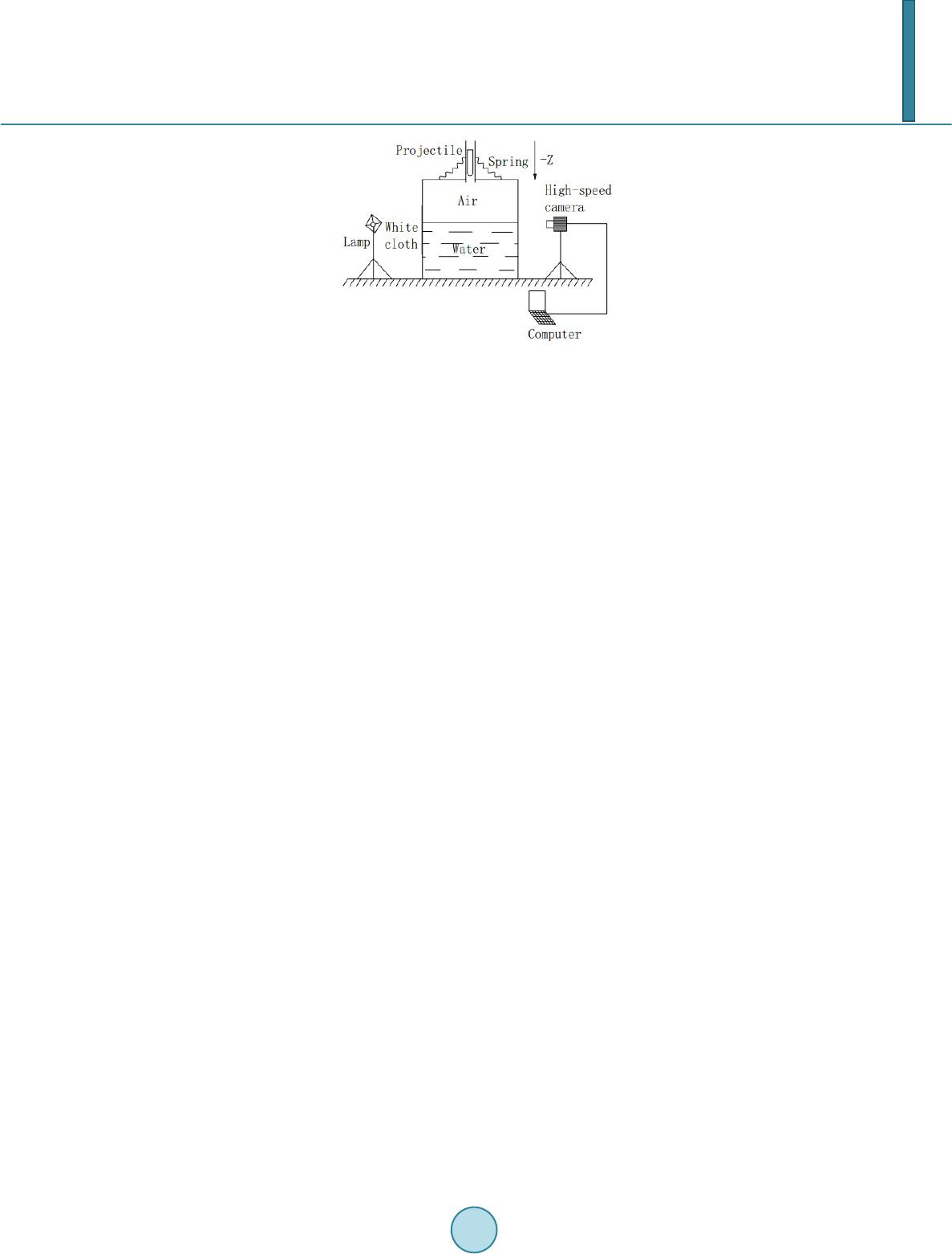 E. R. Yao et al. Figure 1. The experimental system. A 400 cm × 200 cm × 200 cm water tank was designed and installed to simulate water-entry and cavitation. The 20 mm thick surrounding walls and 30 mm thick bottom wall were made from high-strength transparent tempered glass plates. A 50 mm thick damping protective layer was designed and installed on the bottom plate to protect it from damage. The water tank was filled with 0.8 m deep 21˚C tap water. An MS 75 K digital high- speed camera was used to record the penetration of the projectile into the water and cavity evolution. The cam- era speed can be as low as 25 frames per second (fps) and as high as 6000 fps. The camera speed was set to 3500 fps, and exposure time to 285 us. Given the high-speed photography, a high-quality light source and a strobe light opposite the camera were required. A light diffuser of thin white cloth was placed in front of the strobe light to create a background of uniform light intensity and thus optimize the imaging. The spring launch appara- tus was installed on a beam, which was placed on the water tank. The projectile was attached to the spring. Re- laxing the spring sent the projectile through a vertical pipe into the water. The projectile dimension is shown in Figure 2. The plastic projectile has a length of 100.00 mm, a diameter of 17.46 mm, and mass of 17.97 g. 2.2. Experimental Results 2.2.1. Entire Process of Projectile Water Entry Figure 3 shows the entire process of projectile water-entry from projectile entry on the water surface (Fig ure 3(a)) to the formation expansion (Figure 3(b) and Figure 3(c)), and contraction (Figure 3(d)) of a cavity be- hind the projectile and finally the collapse of the cavity into bubbles (F ig ur e 3(e)). Every two adjacent figures had an interval of 4 ms. Figure 3(a) shows the position of the projectile at initial time. The impact of the projec- tile on the water surface, formed upward and outward jetting and a subsequent expanding splash were above the surface. This splash surrounded the projectile, contracted inward, and finally formed surface closure. The up-jet and down-jet with this closure were given particular attention, because the down-jet sprays on the tail of projec- tile and had a downward impact on the projectile, while the air in the atmosphere enters the cavity no longer af- ter surface closure, so that can form the pressure difference inside and outside cavity, so surface closure is one of the most important events in cavitation behind a projectile and significant factor in cavity evolution by May [5]. Figure 3 also shows the evolution of the cavity. Two distinguishable phenomena were the change in cavity dimensions pulling away of the cavity from the free surface. The cavity diameter increased by about 0.5 times from Figur e 5(b) and Figure 5(c). The maximum diameter of the cavity was about 56 mm, about three times the diameter of the projectile, because of the different initial velocity of the projectile, velocity in the case of Shi and Takami [8] [9] much larger than velocity in this paper. However, this maximum diameter was smaller than it, which was nine times the diameter of the projectile. Cavity length also significantly increased. The cavity started to contract before it was pulled away from the free surface by the underwater projectile. This contraction was driven by the difference between the pressure of the cavity and the hydrostatic pressure of the surrounding water. The gravity of the up-splash on the surface exerted a static pressure on the cavity (Figure 3(c)), thereby keeping the top of the cavity below the water surface flat after the cavity was pulled away. The cavity kept contracting until deep closure was achieved. The down-jet formed on the surface closure impacted the cavity wall and formed small holes on it (Figure 3(d)). These holes made the cavity wall unstable with the approach of deep closure (Figure 3(e)), particularly right before deep closure. In fact, the holes may be droplets because the tip of the down-jet is thin and composed of spray. It is believed that the impact between the down- 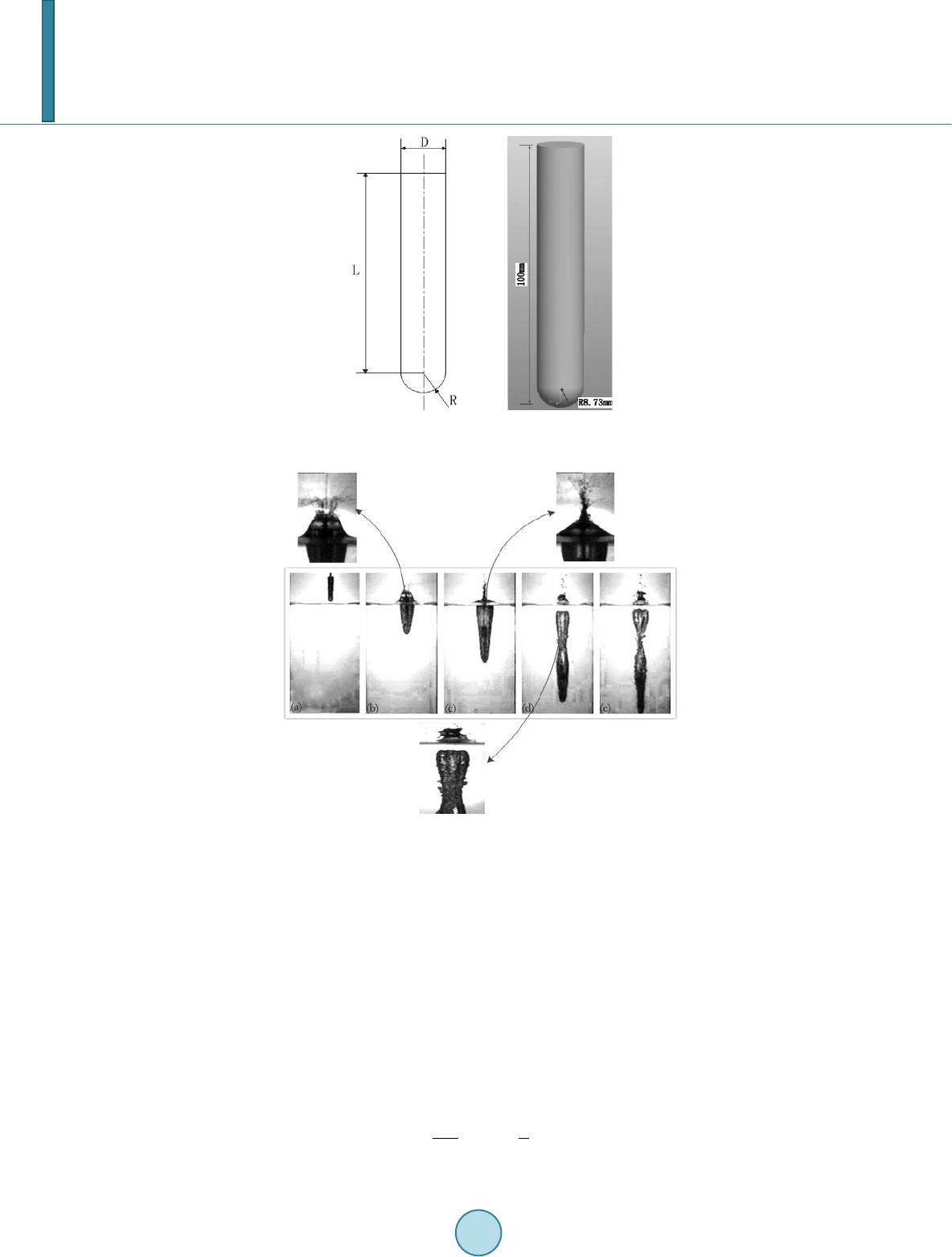 E. R. Yao et al. Figure 2. Two-dimension and three-dimension model. Figure 3. Time history of projectile water-entry and enlarged view. jet and the cavity wall does not make a contribution to the increase of the cavity diameter. The cavity divided into two after deep closure, in the process of fluid circumferential movement, the kinetic energy was gradually converted to fluid pressure potential energy, the expansion rate went down, fluid began to conduct reverse movement when the expansion rate dropped to zero, leading to deep closure or collapse. Figure 3 also shows not only surface and deep closure but also surface closure before deep closure. May [5] confirmed that the time of surface closure affected by the initial velocity of the projectile at atmospheric conditions and that the time of deep closure depended on the time of surface closure. 2.2.2. Projectile Motion For the cavity flows, the liquid phase comes into contact only with the projectile nose. Thus, skin drag can be neglected. Compared with other sources, pressure drag dominates the drag force of a projectile in water. The motion of a projectile with initial velocity penetrating into a fluid along a trajectory in the +z direction can be described by Newton’s second law: 2 0 1 2 p ppw dp dv FmmgAC v dt ρ == − (1) 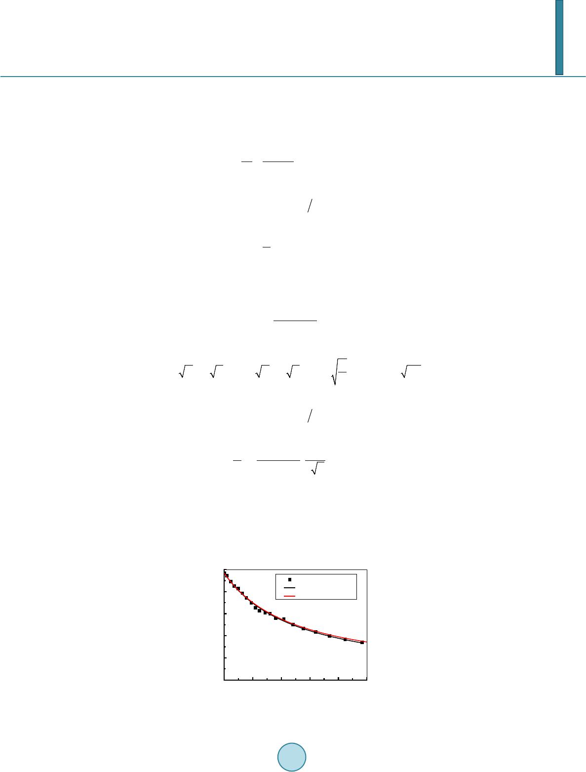 E. R. Yao et al. where is the projectile mass, the penetration velocity of the projectile, the drag force, the projected frontal area of the projectile, and the drag coefficient. 1) Disregarding gravitational effect Assuming that is a constant throughout the water entry process and ignoring gravitational effect in the analysis, we can derive velocity attenuation with time from Equatio n (1): (2) where the velocity decay coefficient, is defined as Integrating Eq uatio n (2), yields penetration as a function of : (3) 2) Considering gravitational effect Assuming that is a constant throughout the water entry process and considering gravitational effect in the analysis, we can also derive velocity attenuation with from Equation (1): 4 2 3 12 2 1 pt ve α α ααα = + − (2') where , , , and are defined as , , , and , where is also defined as Integrating Eq uatio n (2'), yields as a function of : 4 4 1 21 3 1 1ln 2 t pt e zt eg α α ααα α βα − = ⋅+ (3') Figure 4 shows the experimental velocity attenuation of the projectile with time. The curves were fitted through data points to the theoretical Eq uations (2) and (2'). The experimental penetration distance of the projec- tile with time is shown in F igure 5, in which the curves were fitted through data points to the theoretical Equa- tions (3) and (3'), The limited experimental conditions, limited the available experimental results in the early stage of projectile water-entry. The experiment can result in two drag coefficient as fitted by Equations (2) and (3), because the experimental data represented respectively velocity attenuation and penetration with time. Figure 4. Velocity attenuation with time. 0.00 0.01 0.02 0.03 0.04 0.05 0 3 6 9 12 15 speed/m/s time/s experiments theory theory with gravity 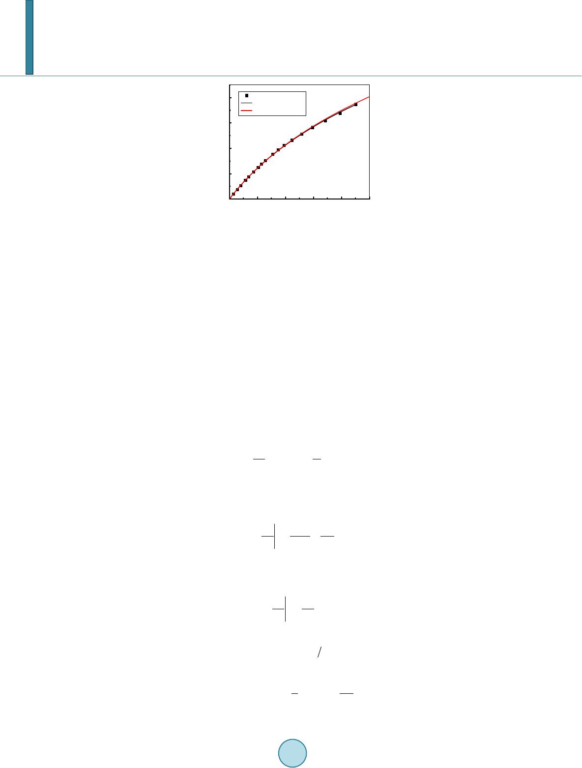 E. R. Yao et al. Figure 5. Penetration distance with time. fitted from Equations (2) and (3) was 2.72 and 2.78, respectively. Thus, the curve fitted from the experi- mental data was consistent with Equations (2) and (3), that is, the were similar. Velocity and penetration distance with time under gravitational effect were obtained from Equations (2) and (3). The velocity and pene- tration distance curves overlapped in the initial stage of water entry and gradually separated in the later stage. Thus, the gravitational effect can be ignored in the initial stage of projectile water-entry, and should be consi- dered in the later stage. The drag coefficient in the experiment was 0.45, obtained from the fitting velocity decay coefficient. The drag coefficient of the projectile was used for the cavity mode in the remaining analysis. 3. Theoretical Analys is 3.1. Cavity Dynamics of Vertical Water Entry Given the complexities of water entry, the dynamic of water-entry cavities has rarely been theoretically analyzed. Duclaux et al. and Aristoff and Bush indicate a new method of describing the transformation of cavities formed by the vertical water-entry of spherical projectiles based on Rayleigh-Besant problems. Guo et al. extends the approach in Duclaux et al. and Aristoff and Bush, to include the cavity dynamics of the horizontal water-entry of cylindrical projectiles. A diagram of the cavity motion is shown in Figure 6. Assuming a high-Reynolds-number, the liquid motion can be described by the Euler equations: (4) The fluid motion can be assumed to be irrotational everywhere and can thus be described as . Inte- grating Equatio n (4) obtains the unsteady Bernoulli equation. If is located at the interface and far from the cavity where no motion exists but can be rewritten as: (5) Birkhff and Caywood (1949) assumed cavity motion to be purely radial or vertical to the cavity axis, and boundary condition, the strength source of cavity wall velocity to be equal to the local fluid radial ve- locity . That is, (6) We then compute for , to determine as: (7) Substituting E quation (7) into Equation (5), and yields the equation for cavity motion: ( ) 2 1 2 P NRR NR ρ ∆ ++ =− (8) 0.00 0.01 0.02 0.03 0.04 0.05 0.0 0.1 0.2 0.3 0.4 z/m time/s experiments theory theory with gravity 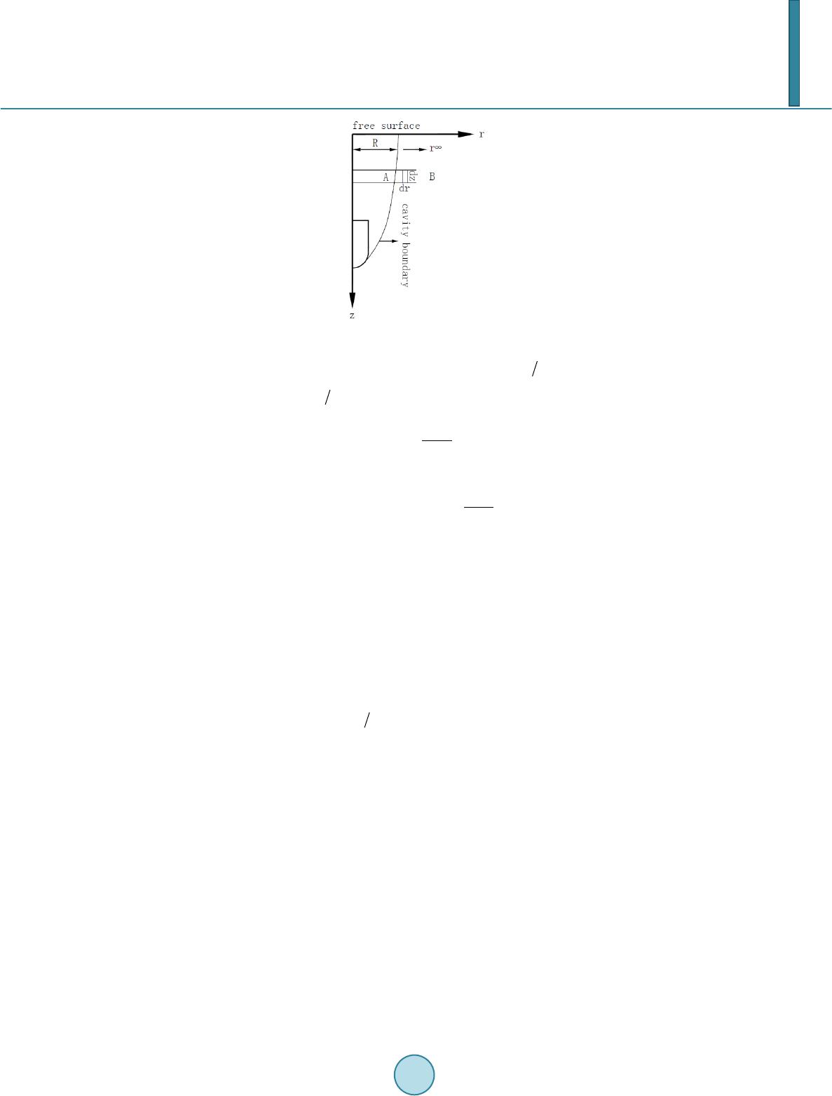 E. R. Yao et al. Figure 6. Cavity motion. where is a dimensionless geometric parameter defined as . Noting that ( ) () () () 22 2 22 21RRRRRRN R •• =⋅+≈⋅++ , reduces Equation (8) for the cavity to (9) Integrating Eq uatio n (11) twice, yields ()( ) 2 22 00 00 2 p P RR Rkvtttt N αρ ∆ = +−−− ⋅ (10) where 0 ≤ α ≤ 1 is the correction factor of projectile nose shapes. Equation (10) describes the evolution of the cavity radius with time, beginning at , when the projectile is at . When the projectile reaches , the cavity radius at is obtained from Equation (10). This equation expresses the evolution of a cavity formed by the water entry of a projectile with any nose shape projectiles. Parameters and 1) Pressure difference Equation (10) still requires the definition of the pressure difference and . Considering surface tension, aerodynamic pressure and gravitational effect, Aristoff et al. defined the pressure difference between pressure in the cavity and the pressure of the surrounding water throughout the entire water entry process as . Given that is far smaller than , surface tension can be neglected; (11) Due to air entering the cavity with characteristic speed , where is assumed to be a constant: 7.5 < < 10.0 [19], and no appreciable pressure gradients arose within the cavity over a range of impact speeds. However, describing cavity evolution just by using the pressure difference according to Aristoff et al. is quite controversial. After all, the shape of the projectile nose and the initial projectile speed are different. Based on the method by Guo et al., this paper uses a simple method of obtaining under gravitational ef- fect. The energy conservation principle, holds that when the cavity radius in fluid reaches its maximum, poten- tial energy in the cavity completely comes from the initial kinetic and potential energy of the fluid. The initial energy is converted from the kinetic and potential energy of lost by the projectile. For a given head radius projectile, when the cavity radius reaches its maximum, the potential energy of the cavity is ( ) 0 00 2 tt p tt tt dEPRRdt dzPSdt dzPSSdz π =∆=∆ =∆− ∫∫ (12) where represents the derivative of the cross-sectional area of the cavity. Then, 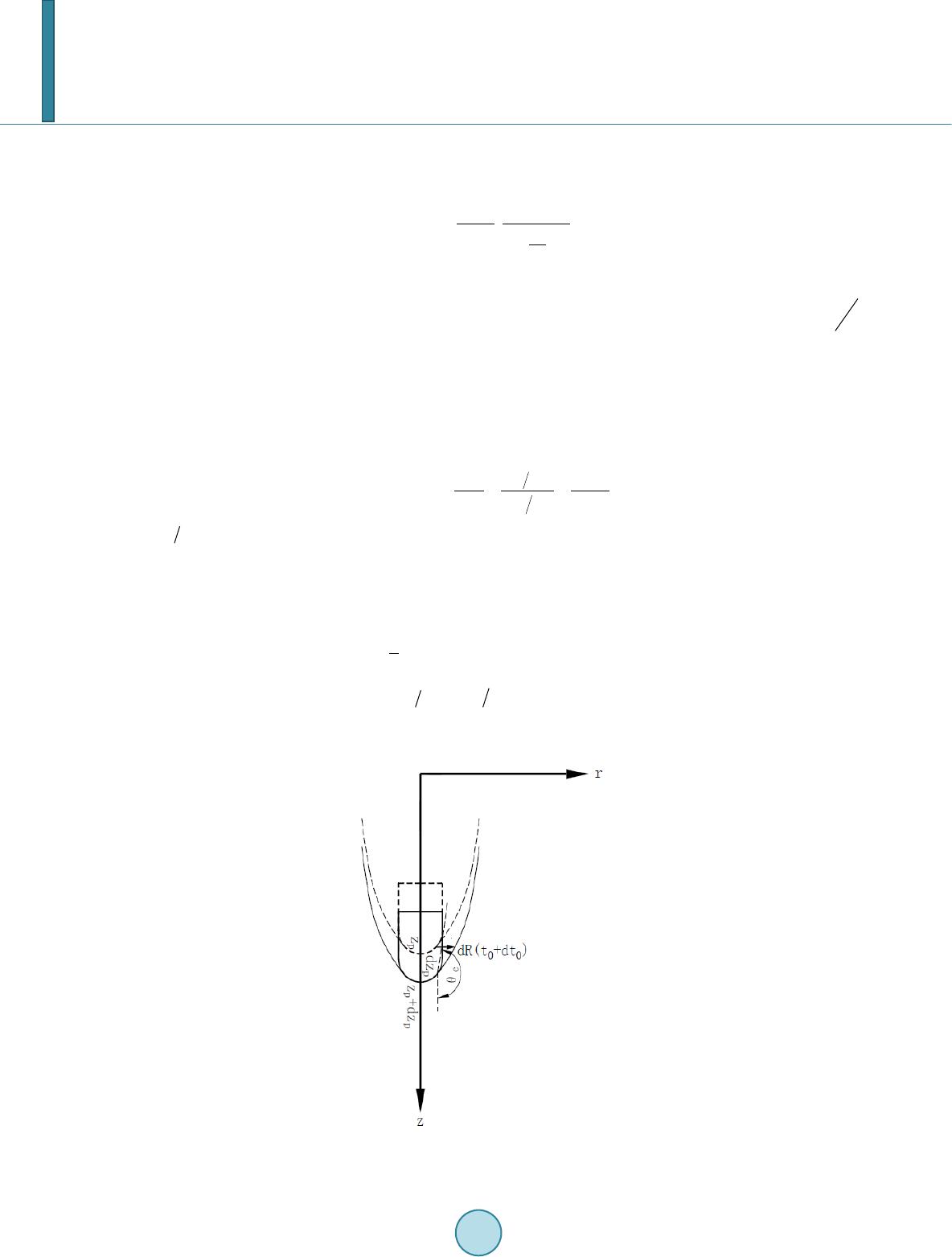 E. R. Yao et al. () 22 2 0 mpp p PRRm vmg πβ ∆ −=− (13) Analyzing Equation (13), yields the pressure difference: (14) where both and are constant. According to the range of the initial velocities, if the initial velocity is not high, a relation between and can be found by employing the initial condition , which is caused by air entering the cavity with characteristic speed . 2) Parameter Based on Figure 7, in Equation (10) is the ratio of the initial radial velocity of the cavity wall at . is distinctly defined for clearer understanding of the parameter. The growth model of a cavity with purely radial motion at from to is shown in Fig ure 7, where the projectile proceeds to and the cavity expands by a certain amount : ( ) ( ) 0 0 0 0 tan tt t c pp p R dR dR dtk dzdzdtv πθ = −= === (15) . The definition of k in Equation (15), indicates that with a constant projectile radius, a larger cavity radius at the projectile nose reduces angle , which contributes to the magnitude of . Thus deter- mines cavity size at the projectile head. Figure 6 shows that the kinetic energy of the fluid in a section within a finite radius can be inte- grated by 22 12 2 rr kw w RR dErudrdzu rdrdz π ρπρ ∞∞ = = ∫∫ (16) With a purely radial motion and , the kinetic energy is expressed as (16') Figure 7. Cavity growth model at .  E. R. Yao et al. where is the cavity radius, and a dimensionless geometric parameter that defines the range of disturbances caused by water impact. The potential energy of the fluid is defined as () ( ) 0 22 0 2 R zR dEPrdr dzP RRdz ππ =∆ =∆− ∫ (17) The change rate of the kinetic energy of the projectile with respect to can be expressed as 2 p t pppp pp dv dE mvmvm g dz dz β =−=− (18) is considered invariable along the of the projectile. (19) is determined through Equation (14) and is related to the drag coefficient, a constant in the low-speed wa- ter-entry. Assuming that , because the time in which the cavity will be filled up, the pressure at an in finite distance being supposed to remain constant, (19') Substituting Equation (2) into Equat ions (14) and (10), transforms the time evolution of the cavity radius at , from (when the projectile head is at ), ()() 2 22 0 000 0 00 2 12 d RC P RRv tttt vt αβρ ∆ =+⋅⋅− −− + (20) When the projectile reaches , the cavity radius at is obtained from Equation (20). If , the evolution of the cavity radius (starting at when the projectile head reaches at , ) with penetration depth can be written as a modified form of the evolution of Equation (20): () () 2 22 0 0 000 00 2exp( ())1exp()exp() 12 d RC P R Rvzzzz vt αβ ββ βρ ∆ =+⋅⋅− −−− + (21) The whole shape of the cavity when the projectile reaches , is obtained from Equation (21). 3.2. Validating of the Cavity Model Figure 8 shows the time evolutions of the cavity radius on the four fixed penetration locations, including the experimental data points, the cavity model based on the pressure model in Aristoff and Bush, and the developed cavity model. Data from the cavity model based on the pressure model were consistent with the experiments in the initial stage, but data from the developed cavity model were more highly consistent. However, surface ten- sion, surface closure, and the down-jet formed before surface closure generated more glaring errors in the model in the later stage of water-entry. In other words, the developed cavity model was not suited for the experiments after surface closure. After surface closure, the cavity follows by an entropic process, and the pressure difference at a fixed position remains variable by Abelson [21]. Figure 9 shows the cavity shape at different times. As for the time of projectile water-entry, the cavity model was consistent with the experiments. However, error between the cavity model and the experimental results was significant in later cavity contraction. Given the larger velocities in the initial stage of projectile water-entry, surface tension only slightly affected the cavity and can thus be ignored. By contrast, the low velocity in the lat- er stage of water-entry indicated that surface tension significant affected the cavity and thus cannot be ignored. The down-jet also developed quickly after surface closure and impacted the cavity wall shortly, thereby signifi- cantly affecting the motion of the cavity wall. As for the cavity shape of the projectile water-entry, the error between the cavity model and the experiments was mainly observed near the free surface, because projectile impact on the water near the free surface caused a larger impact force, and the hydrostatic pressure based on penetration distance was small. Thus, the weak forces, 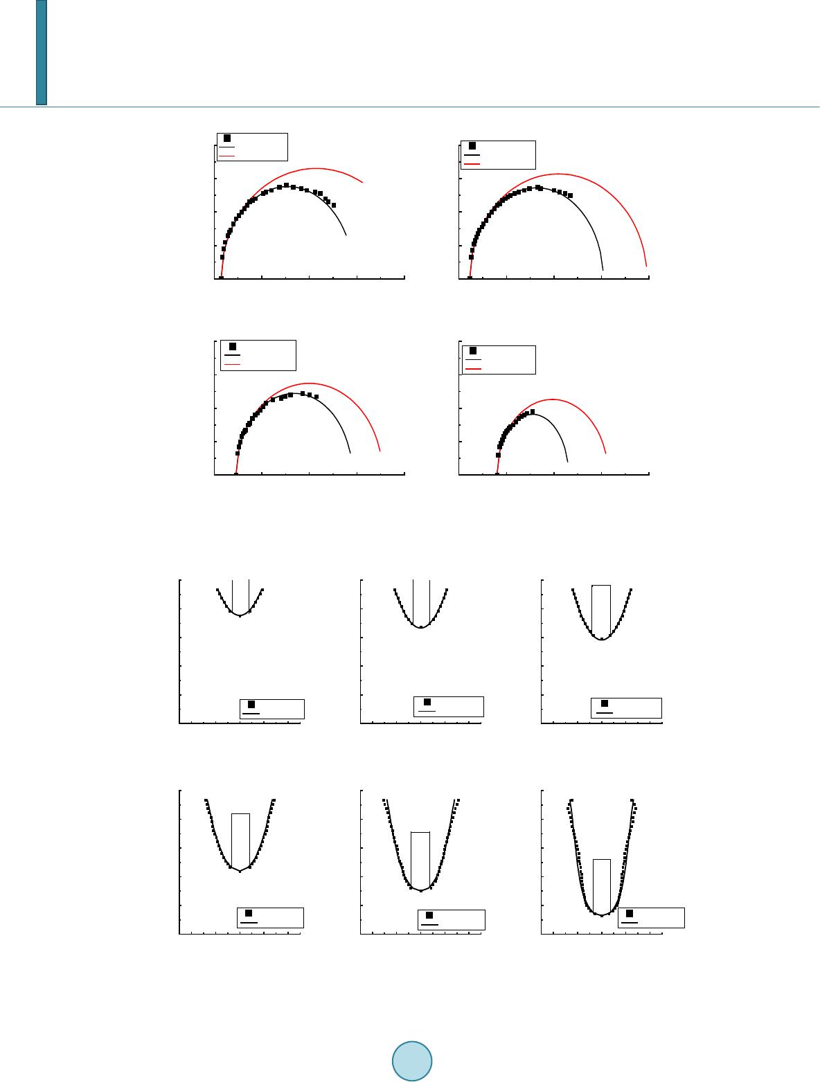 E. R. Yao et al. Figure 8. Time evolution of cavity radius at fixed locations (penetration distance = (a) 0.019 m; (b) 0.03 m; (c) 0.061m; (d) 0. 12 37 m). Figure 9. Location evolutions of cavity at fixed times(fixed time = (a) 4.571 ms; (b) 6. 28 5 ms ; (c) 7.9 99 ms ; (d) 11.4 28 ms; (e) 14.856 ms; (f) 24.570 ms). 0.000.01 0.020.03 0.04 0.00 0.01 0.02 0.03 0.04 a R/m time/s experi ment s R R with dertP[19] 0.000.01 0.020.03 0.04 0.00 0.01 0.02 0.03 0.04 d c b R/m time/s experi ment s R R with dertP[19] 0.000.01 0.020.03 0.04 0.00 0.01 0.02 0.03 0.04 R/m time/s experi ment s R R with dertP[19] 0.000.01 0.020.03 0.04 0.00 0.01 0.02 0.03 0.04 R/m time/s experi ment s R R with dertP[19] -0.04 -0.020.000.020.04 -0.25 -0.20 -0.15 -0.10 -0.05 0. 00 z/m R/ m experi ments theory -0.04 -0.020.000.020.04 -0.25 -0.20 -0.15 -0.10 -0.05 0. 00 z/m R/ m experi ments theory -0.04 -0.020.000.020.04 -0.25 -0.20 -0.15 -0.10 -0.05 0. 00 z/m R/ m experi ments theory -0.04 -0.020.000.020.04 -0.25 -0.20 -0.15 -0.10 -0.05 0. 00 z/m R/ m experi ments theory -0.04 -0.020.000.020.04 -0.25 -0.20 -0.15 -0.10 -0.05 0. 00 z/m R/ m experi ments theory -0.04 -0.020.000.020.04 -0.25 -0.20 -0.15 -0.10 -0.05 0.00 f e d c b z/m R/ m experi ments theory a  E. R. Yao et al. including surface tension increase the error. As for the area far from the free surface, the difference between the hydrostatic pressure in the flow around the cavity and the pressure in the cavity more significantly affected the cavity, but the surface tension only had a marginal effect. Thus, surface tension in the developed cavity model can be ignored, and the difference between the hydrostatic pressure in the flow around the cavity and the pres- sure in the cavity should be considered, consistent with the assumption of the cavity model. 4. Conclusions The vertical water-entry behaviors of bullet-shaped projectiles were experimentally and theoretically studied. The projectile motion was recorded by a high-speed camera, thus, we were able to observe behaviors of the pro- jectile water-entry, such as the jet, splash, and cavity. We also obtained the motion equations of the projectile and the cavity. Based on the solution to the Rayleigh-Besant problem, a theoretical model was developed to de- scribe the evolution of the cavity shape, including the time evolutions of the cavity on fixed locations and its lo- cation evolutions at fixed times. The following conclusions can be drawn: The transient characteristics of the cylindrical projectile vertical water-entry at middle speed (i.e., the cavity, splash, up-jet, and down-jet) observed in the present experiment are basically identical to those in previous re- search. The high-speed camera provided new information on the detailed process of water-entry. The extent of cavity expansion, the instability of the cavity wall. Above all, surface closure before deep closure was docu- mented by the authors. Gravitational effect can be ignored in the initial stage of projectile water-entry and considered in the later stage. Under gravitational effect, the square of the maximum cavity radius is linear with the square of projectile impact velocity at a fixed penetration distance. The constant in the linear relationship is related to the difference between the pressure in the cavity and the hydraulic pressure in the flow field around the cavity at the same ho- rizontal level. The theoretical cavity model based on the solution to be Rayleigh-Besant problem can predict the evolution of cavity shape in the initial stage to a great extent, including the time evolutions of the cavity on fixed locations and its location evolutions at fixed times. However, surface tension, surface closure, and the down-jet formed before surface closure generated more glaring errors in the model in the later stage of projectile water-entry. Thus, surface tension, and closure may significantly affects cavity shape evolution. The exact reason for this ef- fect warrants further study. Acknowledgements This work is partly supported by the National Natural Science Foundation of China (51176145) in XJTU over the period of 2011-2015, to which the authors are most grateful. References [1] Worthington, A.M. and C ole, R.S. (1897) Impact with a Liquid Surface, Studied by the Aid of Instantaneous Photo- graphy. Philosophical Transactions of the Royal Society of London. Series A, Containing Papers of a Mathematical or Physical Character, 18, 137-148 . http://dx.doi.org/10.1098/rsta.1897.0005 [2] May, A. and Woodhull, J.C. (1948) Drag Coefficients of Steel Spheres Entering Water Vertically. Journal of Applied Physics, 19, 1109 -11 21 . http://dx.doi.org/10.1063/1.1715027 [3] May, A. an d Woodhull, J.C. ( 1950 ) The Virtual Mass of a Sphere Entering Water Vertically. Journal of Applied Phys- ics, 21, 1285-12 89 . http://dx.doi.org/10.1063/1.1699592 [4] May, A. (1951) Effect of Surface Condition of a Sphere on Its Water-Entry Cavity. Journal of Applied Physics, 22, 1219-1222. http://dx.doi.org/10.1063/1.1699831 [5] May, A. (1952) Vertical Entry of Missiles into Water. Journal of Applied Physics, 23, 1362-13 72 . http://dx.doi.org/10.1063/1.1702076 [6] Gilbarg, D. and Anderson, R.A. (1948) Influence of Atmospheric Pressure on the Phenomena Accompanying the Entry of Spheres into Water. Journal of Applied Physics, 19, 127 -139 . http://dx.doi.org/10.1063/1.1698377 [7] Birkhoff, G. and Caywood, T.E. (1949) Fluid Flow Patterns. Journal of Applied Physics, 20, 646-659 . http://dx.doi.org/10.1063/1.1698450 [8] Shi, H.H., I t oh, M. and Takami, T. (2000) Optical Observation of the Supercavitation Induced by High -Speed Water Entry. Journal of Fluids Engineering, 122 , 80 6 -810 . http://dx.doi.org/10.1115/1.1310575  E. R. Yao et al. [9] Shi, H.H. and Takami, T. (2001) Some Progress in the Study of the Water Entry Phenomenon. Experiments in Fluids, 30, 475-477. http://dx.doi.org/10.1007/s003480000213 [10] Yan, H.M., Liu, Y.M., Kominiarczuk, J. and Dick, K.P. (2009) Cavity Dynamics in Water Entry at Low Froude Nu m- bers. Journal of Fluid Mechanics, 641 , 441 . http://dx.doi.org/10.1017/S0022112009991558 [11] Berg mann, R., van der Meer, D., Gekle, S., van der Bos, A. and Lohse, D. (2009) Controlled Impact of a Disk on a Water Surface: Cavity Dynamics. Journal of Fluid Mechanics, 633, 3 81-40 9. http://dx.doi.org/10.1017/S0022112009006983 [12] Truscott, T.T. an d Techet, A.H. (2009) Water Entry of Spinning Spheres. Journal of Fluid Mechanics, 625, 1 35 -165 . http://dx.doi.org/10.1017/S0022112008005533 [13] Aristoff, J.M., Truscott, T.T., Techet, A.H. and Bush, J.W.M. (2010) The Water Entry of Decelerating Spheres. Phys- ics of Fluids, 22. [14] Rabi ee, A., Alishahi, M.M., Emdad, H. and Saranjam, B. (2011) Part A: Experimental Investigation of Unsteady Su- percavitating Flows. Iranian Journal of Science and Technology Transactions of Mechanical Engineering, 35, 15-29 . [15] Rabi ee, A., Alishahi, M.M., Emdad, H. and Saranjam, B. (2011) Part B: Numerical Investigation of Unsteady Superca- vitating Flows. Iranian Journal of Science and Technology Transactions of Mechanical Engineering, 35, 31-46. [16] Birkhoff, G. and Zaranton ello, E.H. (1957) Jets, Wakes, and Cavities. Academic, New York. [17] Lee, M., Longoria, R.G. and Wilso n, D.E. (1997) Cavity Dynamics in High-Speed Water Entry. Physics of Fluids, 9, 540. http://dx.doi.org/10.1017/S0022112008005533 [18] Ducl aux, V., Caille, F., Duez, C., Ybert, C., Bocquet, L. and Clanet, C. (2007) Dynamics of Transient Cavities. Jour- nal of Fluid Mechanics, 591, 1-19. [19] Aristoff, J.M. and Bu s h, J.W.M. (2009) Water Entry of Small Hydrophobic Spheres. Journal of Fluid Mechanics, 619, 45. http://dx.doi.org/10.1017/S0022112008004382 [20] Gu o, Z.T., Zhang, W., Xiao, X.K., Gang, W. and Ren, P. (2012) An Investigation into Horizontal Water Entry Beha- viors of Projectiles with Different Nose Shapes. International Journal of Impact Engineering, 494, 3-60. [21] Abelson, H.I. (1970) Pressure Measurements in the Water-Entry Cavity. Journal of Fluid Mechanics, 44, 129 -144 . http://dx.doi.org/10.1017/S0022112070001738
|