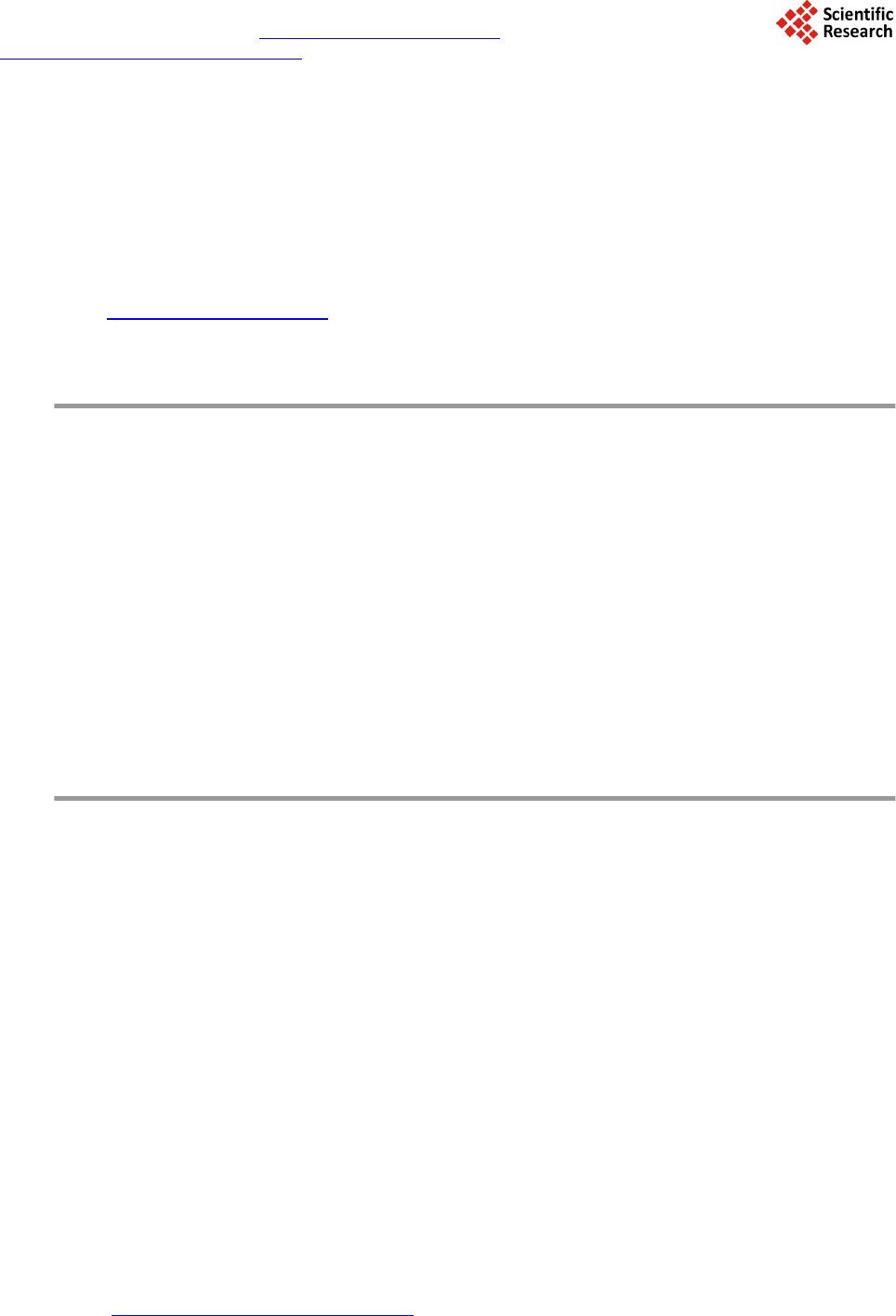
 Journal of Applied Mathematics and Physics, 2014, 2, 94-107 Published Online April 2014 in SciRes. http://www.scirp.org/journal/jamp http://dx.doi.org/10.4236/jamp.2014.25013 How to cite this paper: Ellman, R. (2014) Gravito-Electric Power Generation. Journal of Applied Mathematics and Physics, 2, 94-107. http://dx.doi.org/10.4236/jamp.2014.25013 Gravito-Electric Power Generation Roger Ellman The-Origin Foundation, Inc., Santa Rosa, CA, USA Email: RogerEllman@The -Origin.org Received October 2013 Abstract It is now possible to deflect gravitational action away from an object so that the object is partially levitated. That effect makes it possible to extract energy from the gravitational field, which makes the generation of gravito-electric power technologically feasible. Such plants would be similar to hydro-electric plants and would have their advantages of not needing fuel and not polluting the environment. However, gravito-electric plants could be much smaller than hydro-electric plants; their location would not be restricted to suitable water elevations, and the plants and their pro- duced energy would be much less expensive. Gravito-electric power can be placed into operation now. It can replace all existing nuclear and fossil fuel plants, and would essentially solve the prob- lem of global warming to the extent it is caused by fossil fuel use. The physics development is comprehensively presented. That is followed by the engineering design. Keywords Gravitation, Power Generation, Global Warming 1. Summary Development Light normally travels in a straight direction. But, when some effect slows a portion of the light wave front the direction of the light is deflected. In Figure 1, the shaded area propagates the arriving light at a slower velocity, v’, than the original velocity, v, [its index of refraction, n’, is greater] so that the direction of the wave front is deflected from its original direction. A slowing of part of its wave front is the mechanism of all bending or deflecting of light. In an optical lens, as in Figure 2, light propagates more slowly in the lens material than outside the lens. The amount of slowing in different parts of the lens depends on the thickness of the lens at each part. In the figure the light passing through the center of the lens is slowed more than that passing near the edges of the lens. The result is the curving of the light wave front. “Gravitational lensing”, Figure 3, is an astronomically observed effect in which light from a cosmic object too far distant to be directly observed from Earth becomes observable because a large cosmic mass [the “lens”], located between the Earth observers and that distant object, deflects the light from the distant object as if focus- ing it, somewhat concentrating its light toward Earth enough for it to be observed from Earth. The light rays are so bent because the lensing object slows more the portion of the wave front that is nearer to it than it slows the farther away portion of the wave front. The same effect occurs on a much smaller scale in the diffraction of light at the two edges of a slit cut in a flat 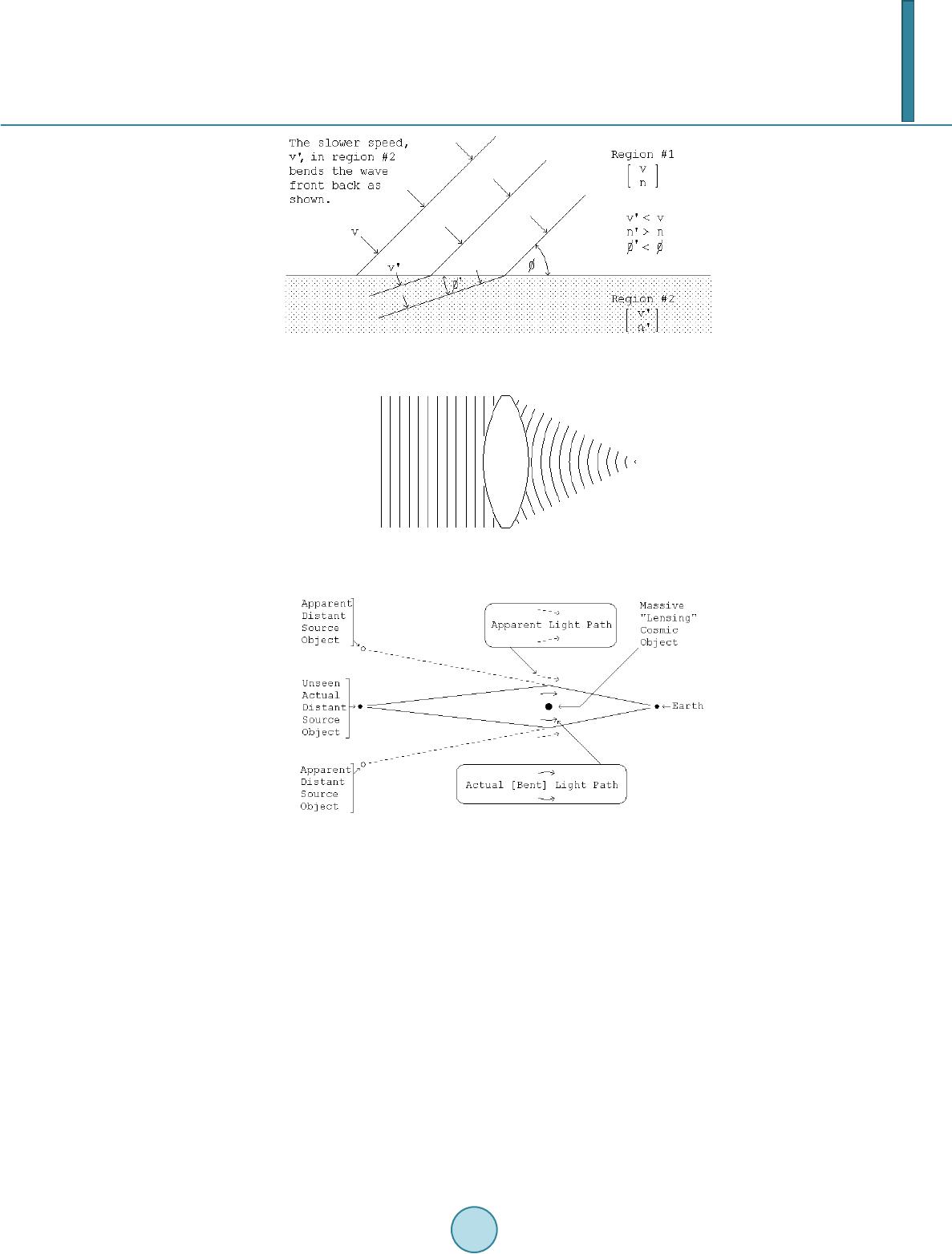 R. Ellman Figure 1. Deflection of Light’s Direction by Slowing of Part of Its Wave Front. Figure 2. The Bending of Light’s Wave Front by an Optical Lens. Figure 3. Gravitational Lensing Bending of Light Rays. thin piece of opaque material as in Figure 4. The bending is greater near the edges of the slit because the slow- ing is greater there. The effect of the denser material in which the slit is cut slows the portion of the wave front that is nearer to it more than the portion of the wave front in the middle of the slit. In both of these cases, gravitational lensing and slit diffraction, the direction of the wave front is changed be- cause part of the wave front is slowed relative to the rest of it. In the case of gravitational lensing the part of the wave front nearer to the “massive lensing cosmic object” is slowed more. In the case of diffraction at a slit the part of the wave front nearer to the solid, opaque material in which the slit is cut is slowed more. But, neither of the cases, gravitational lensing and slit diffraction, involves the wave front passing from trav- eling through one substance to another as in the original illustration of Figure 1. The wave front in the gravita- tional lensing case is traveling only through cosmic space. The wave front in the slit diffraction case is traveling only through air. There is no substance change to produce the slowing. What is it that slows part of the wave front thus producing the deflection? In the case of gravitational lensing the answer is that the effect is caused by gravitation. There is no other physical effect available. But how does gravitation produce slowing of part of the incoming wave front so as to deflect it? Gravitation, at least as it is generally known and experienced, causes acceleration, not slowing. 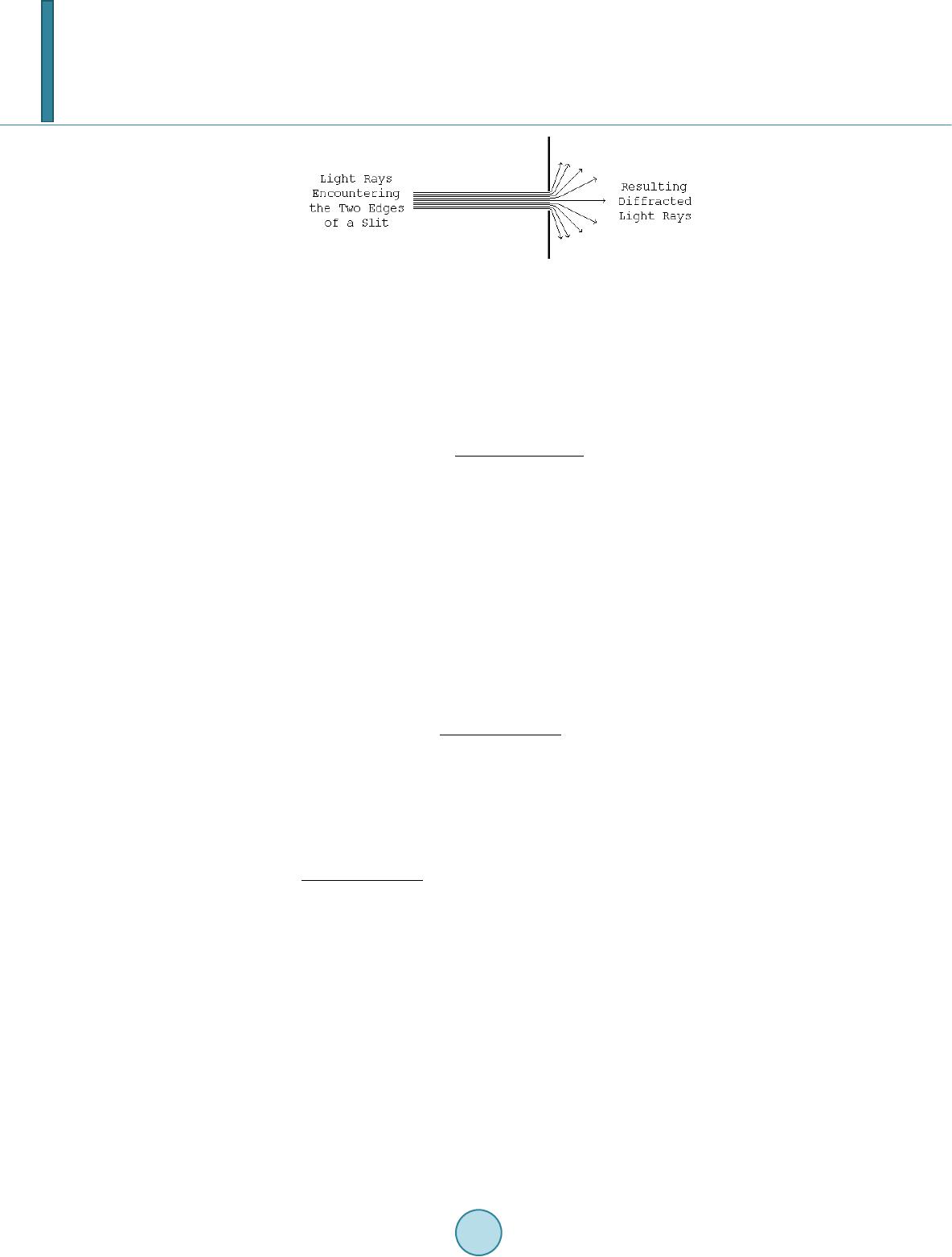 R. Ellman Figure 4. Diffraction at a Slit Causing Bending of Light Rays. 2. Electro-Magnetic Field (Light) and Gravitational Field (Gravity) 2.1. Light Given two particles [e.g. electrons or protons] that have electric charges, the particles being separated and with the usual electric [Coulomb] force between them, if one of the charged particles is moved the change can pro- duce no effect on the other charge until a time equal to the distance between them divided by the speed of light, c, has elapsed. For that time delay to happen there must be something flowing from one charge to the other at speed c [a fundamental constant of the universe] and each charge must be the source of such a flow. That electric effect is radially outward from each charge, therefore every charge must be propagating such a flow radially outward in all directions from itself, which flow must be the “electric field”. When such a charge moves with varying velocity it propagates a pattern called electromagnetic field outward into space. Light is that pattern, that field traveling in space. Since light’s source is a charged particle that, whether the particle is moving or not, is continuously emitting its radially outward flow that carries the affect of its charge, then light’s electromagnetic field is a pattern of variations in that flow due to the charge’s varying velocity. 2.2. Gravity Given two masses, i.e. particles that have mass [e.g. electrons or protons], being separated and with the usual gravitational force [attraction] between them, if one of the masses is moved the change can produce no effect on the other mass until a time equal to the distance between them divided by the speed of light, c, has elapsed. For that time delay to happen there must be something flowing from one mass to the other at speed c and each particle, each mass must be the source of such a flow. That gravitational effect is radially outward from each mass, therefore every mass must be propagating such a flow radially outward in all directions from itself, which flow must be the “gravitational field”. 2.3. That Flow We therefore find that the fundamental particles of atoms, of matter, which have both electric charge and gravi- tational mass, must have something flowing outward continuously from them and: • Either the particles have two simultaneous, separate outward flows, one for the effects of electric charge and another for gravitation, or • They have one common universal outward flow that acts to produce all of the effects: electric and electro- magnetic field [light] and gravitational field [gravity]. There is clearly no contest between the alternatives. It would be absurd for there to be two separate, but si- multaneous, independent outward flows, for the two different purposes. And, the single outward Flow from par- ticles, carrying both the electric and electromagnetic field and the gravitational field, means that gravitational field can have an affect on light, on electro-magnetic field because they both are the same medium – the univer- sal outward Flow. Gravitational lensing is experimentally observed gravitational field affecting light [1]. 3. Gravitational Slowing/Deflection of Light Because that universal outward flow originates at each particle and flows radially outward in all directions its density or concentration decreases inversely as the square of distance from the source of the flow. At a large  R. Ellman distance from the source the wave front of a very small portion of the total spherical outward flow is effectively flat—a “plane flow”. As presented in detail in The Origin and Its Meaning [1], two such universal flows encountering each other [flowing through each other] interfere with each other, that is each slows the flow of the other. The effect is proportional to the density or concentration of each flow. Picturing Flow #1 of Figure 5, as that from a “lensing” gravitational mass and Flow #2 as that of the light from a distant object, then the figure depicts how the flow of the “lens” slows part of the wave front of the flow of the propagating light. The slowing is greater for rays of light that pass close to the lens and is less for those farther out. Thus the wave front of the light is deflected or bent as in the actually observed “gravitational lens- ing”. In “gravitational lensing” gravitation produces deflection of the flow that carries light. That deflected flow is the same flow that also simultaneously carries gravitation. Thus the gravitational flow from one mass can pro- duce deflection of the gravitational flow from another mass. Therefore, a properly configured material structure can deflect gravitation away from its natural action, re- ducing the natural gravitation effect on objects that the gravitation would otherwise encounter and attract. That same effect, on a vastly reduced scale, produces the deflection, the bending of the light direction that is seen in slit diffraction. In the diffraction effect the role of the “massive lensing cosmic object” is performed by the individual atoms making up the opaque thin material in which the slit is cut. That effect shows that the gra- vitational lensing process, involving immense cosmic masses, can be implemented on Earth on a much smaller scale practical for human use. 4. The Energy Aspect and the Source of the Flow But, changing the “natural gravitation effect” means changing the gravitational potential energy of objects in the changed gravitational field. If the energy is changed where does the difference come from or go to? The potential energy for an object of mass, m, at a height, h, in a gravitational field is truly potential. It is the kinetic energy that the mass would acquire from being accelerated in the gravitational field if it were to fall. The greater the mass, m, the greater the kinetic energy, ½·m·v2. The greater the distance, h, through which the mass would fall the greater the time of the acceleration, the greater the velocity, v, achieved, the greater the kinetic energy, ½·m·v2. While at rest at height h [as on a shelf] the total mass of the object is the same as its rest mass. The object has no actual “potential energy”. It is merely in a situation where it could acquire energy, acquire it by falling in the gravitational field. Falling, the mass of the object increases as its velocity increases, reflecting its gradually ac- quired kinetic energy. Since, until it falls, the object does not have the energy that it will acquire when it falls in the gravitational field the energy that it acquires must come from the gravitational field. The energy of gravitational field is in its flow radially outward from all gravitational masses. The flow is a flow of the potential for energy, realized at any encounter with another gravitational mass Figure 5. The Encounter of Two Flows. 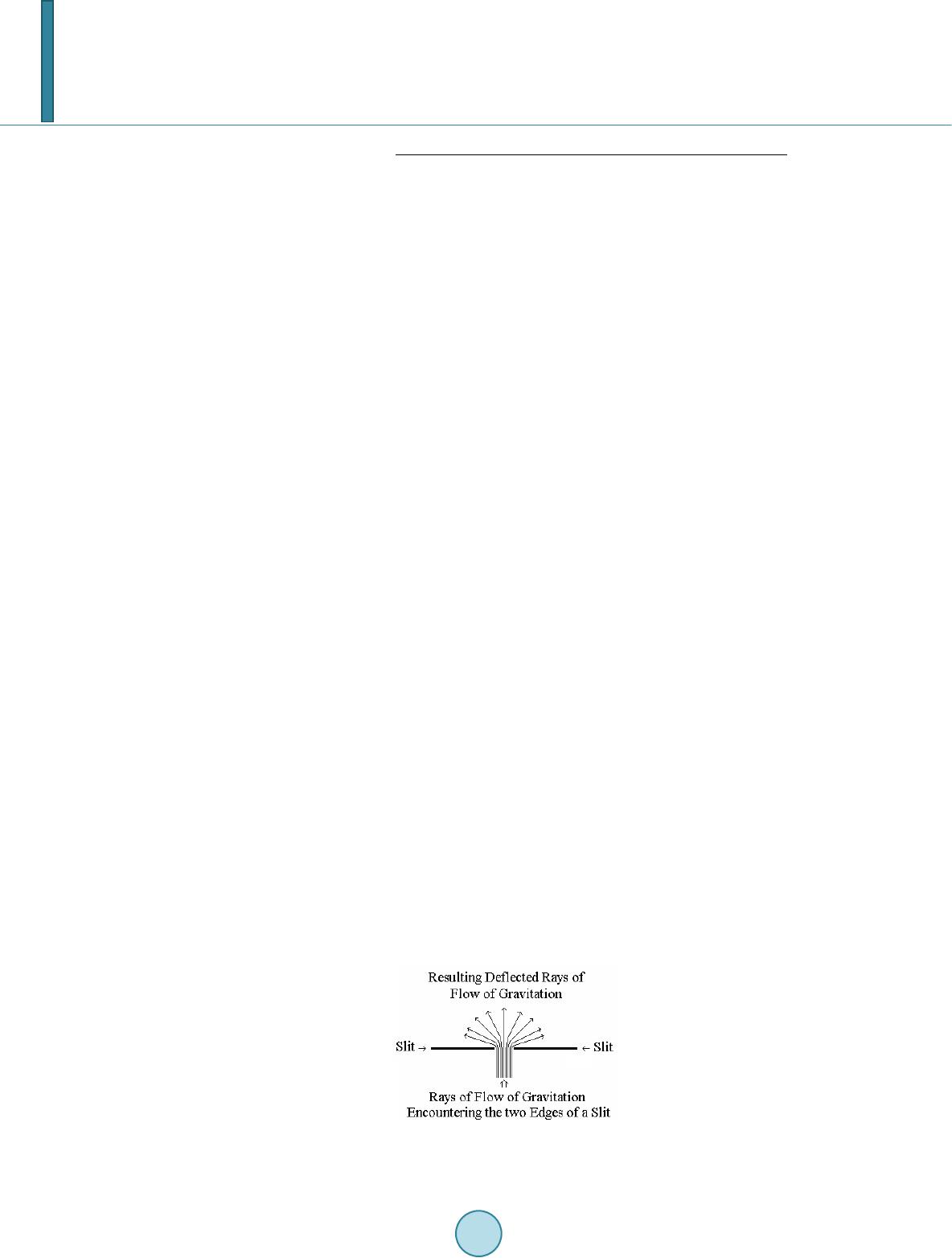 R. Ellman • That flow creates potential energy, creates the situation where kinetic energy could be acquired, at any gra- vitational mass that it encounters. • It does so continuously, replenishing and replenished by the on going continuing outward flow. • It does so continuously, regardless of the number or amount of masses encountered and regardless of their distance from the source of the flow. • At each encountered mass the amount of the flow varies with the magnitude of its source mass and varies inversely as the square of the distance from it. But, for there to be a continuous flow outward from each mass particle, each must be a supply, a reservoir, of that which is flowing. The original supply of the flow of gravitational potential energy, came into existence at the “Big Bang” the beginning of the universe. If that immense reservoir of energy could be tapped by tapping some of its appearance in its outward flow, which is the gravitational field, it could supply all of civilization’s energy needs cheaply, cleanly, and perma- nently without [for practical human/Earth purposes] being used up. Since the original “Big Bang” the outward flow has been very gradually depleting the original supply. That process, an original quantity gradually depleted by flow away of some of the original quantity is an exponential decay process and the rate of the decay is governed by its time constant. In the case of the overall universal de- cay, appearing among other places in the outward flow from every gravitating mass, the time constant is about τ = 3.57532·1017 seconds (≈ 11.3373·109 years). [1]. 5. Tapping the Energy of the Gravitational Field The general vertically upward outward flow of gravitational energy can be tapped by deflecting part of a local region’s gravitational flow away from its normal vertical direction. That produces above that local region a re- gion of lesser gravitation than its surroundings of normal gravitation. That can be configured to produce an im- balance in a rotary device above it powering its rotation analogously to a water wheel. That rotational energy, connected to an electric generator, can generate electrical energy, i.e. useful electric power. Figure 6, below, [Figure 4 but now rotated 90˚] illustrates such deflection using a single slit. Multiple such slits parallel to each other would spread the deflection left and right in the figure. Additional multiple such slits at right angles to the first ones would spread the deflection over a significant area. 6. Gravitation Deflector Design The edges of the slit in Figure 6 are actually rows of atoms. A cubic crystal, such as of Silicon, consists of such rows of atoms, multiple rows and rows at right angles, all equally spaced, Figure 7—a naturally occurring con- figuration of the set of slits required for deflection of gravitation. The flow from each of the cubic crystal’s atoms is radially outward. Therefore its concentration falls off as the square of distance from the atom. The amount of slowing of an incoming gravitational flow and therefore the amount of its resulting deflection, depends on the relative concentration of the atoms’ flow and of the overall gravitational flow. In the case of diffraction of the flow of light at a slit the concentration of the flow from the atoms of the slit material is comparable to the concentration in the horizontal flow of the light, because the light originates from a local source, not from the Earth’s immense gravitation. But for the flow from the atoms of the slit to deflect the much more concentrated vertically upward flow of Figure 6. Slit Diffraction, the Basic Element of a Gravitational Deflector. 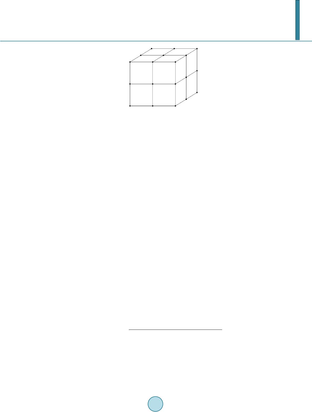 R. Ellman Figure 7. A Small Piece of a Cubic Crys tal . Earth’s gravitation the flow from the atoms of the slit must also be much more concentrated. The only way to achieve that more concentrated flow is to create a configuration in which the flow of Earth’s gravitation is forced to pass much closer to the atoms of the slit so that, per the inverse square variation in the atoms’ flow, it will pass through a concentration of the slit atom’s flow comparable to the concentration in the Earth’s gravita- tional flow. The spacing between the edges of the diffracting slit is about 5 × 10⁻⁶ meters. The spacing of the atoms at the corners of the “cubes” in a Silicon cubic crystal is 5.4 × 10⁻¹⁰ meters. As developed in the references, an in- ter-atomic spacing of less than 3 × 10⁻¹⁹ meters, much closer than the natural spacing in the Silicon cubic crystal, is required to obtain deflection of a major portion of the incoming Earth’s gravitational flow. Such a close atomic spacing cannot be obtained by directly arranging for, or finding a material that has, such a close atomic spacing. However, that close an atomic spacing can be effectively produced relative to just the ver- tical flow of gravitation by slightly tilting the Silicon cubic crystal’s cubic structure relative to the vertical. Figure 8, illustrates the tilting, schematically and not to scale, and shows how it increases the number of crystal atoms closely encountered by the upward gravitational flow. Pure, monolithic, Silicon cubic crystals are grown commercially in diameters from 25.4 millimeters (1 inch) to 300 millimeters (11.8 inches) for making the “chips” used in many electronic devices. By appropriate tilting of the cubic structure each of its 5.4 × 10⁻¹⁰ meters inter-atomic spaces is effectively sub-divided into 1010 “sub-spaces” each of them 5.4 × 10⁻²⁰ meters long and with an atom in each. A 4.5 millimeters shim on a 300 millimeters diameter Silicon cubic crystal ingot produces such an effect, producing a tilt tangent = 0.015 for a tilt angle = 0.86˚ that produces the objective effective sub-division of the crystals’ natural inter-atomic spacing, a sub-division that acts only on vertical flow, as of gravitation. The gravitational deflector requires a large, thick piece of Silicon cubic crystal rather than the thin wafers sawed from the “mother” crystal for “chip” making. Per the detailed analysis in the references, The Silicon cubic crystal ingot for the deflector is to be: • Diameter appropriate to the application, • 0.5 meters or more thick, • with the orientation of the cubic structure marked for proper placement of tilt-generating shims, and • with the bottom face of the cylinder sawed and polished flat at a single cubic structure plane of atoms. Mean free path [MFP] is the average straight line distance a moving particle travels between encounters with another particle. For atoms in solid matter the mean free path is [] [] Atoms PerVolumeAtom Cross-Se 1 ction MEP ⋅ = (1) For the Earth the atoms per unit volume is on the order of 5 × 1028 per cubic meter. In the cubic crystal deflector the atomic spacing produced by the tilt is on the order of 10 - 20 meters. There- fore each atom has cross-sectional space available to it of a circle of that diameter so that for this purpose the atom’s cross-section area is [π/4] × [10−20]2 = 8 × 10−39 square meters. For targets as fine as those in the cubic crystal deflector, the mean free path in the Earth’s outer layers is, therefore 2.5 × 10⁹ meters 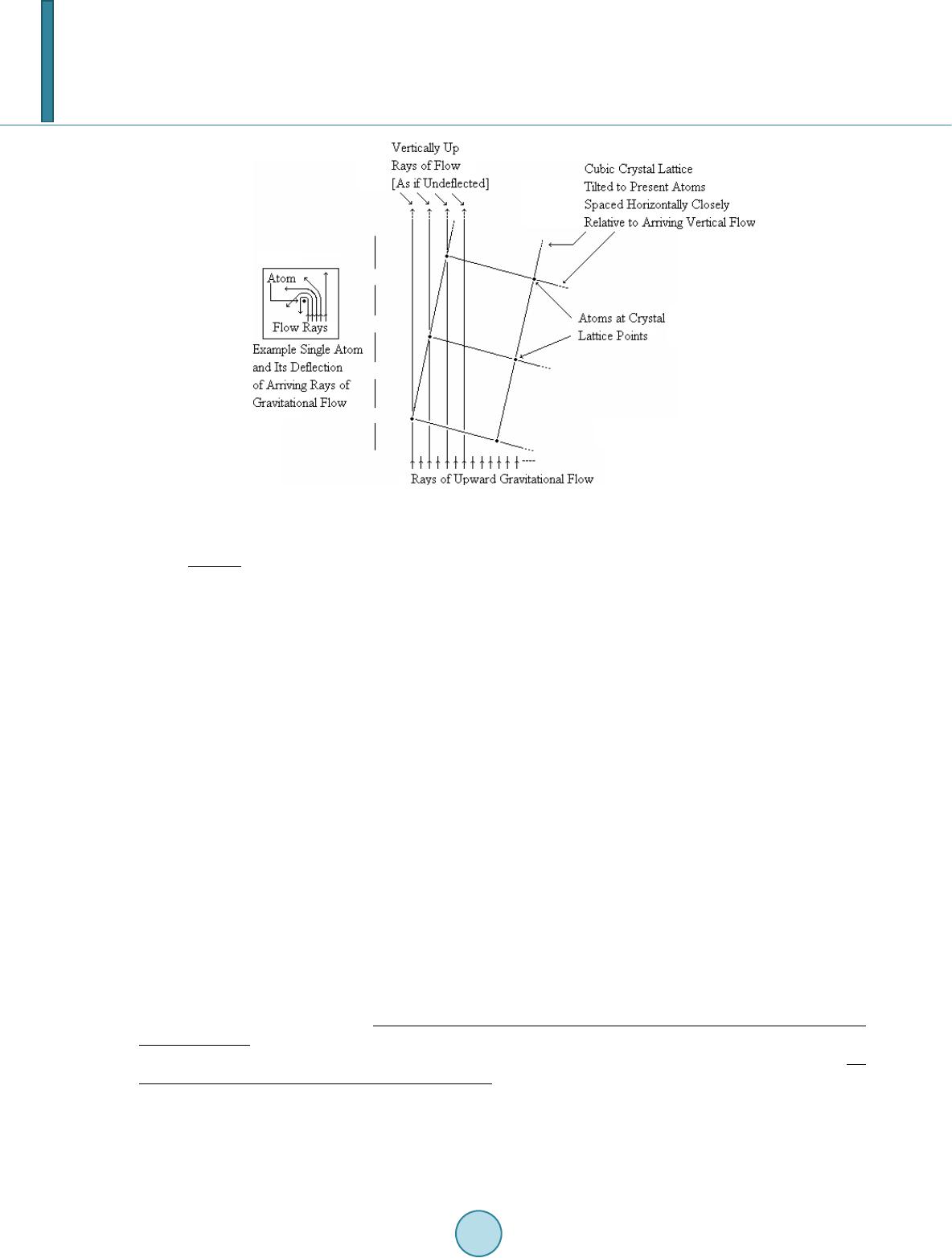 R. Ellman Figure 8. Cubic Crystal Lattice Tilted for Effective Gravitational Flow Deflection. The mean free path in the 0.5 meters thick minutely tilted Silicon cubic crystal ingot for intercepting Earth’s natural vertically outward gravitation is ½ the 0.5 meters thickness of the ingot. Therefore, the gravitational def- lector is about 1010 times more effective than the natural Earth at intercepting Earth’s natural gravitation. However, that effectiveness is only for vertical rays of flow. The Silicon crystal’s mean free path for non-vertical flow—flow already once deflected within the crystal—is that of Earth, 2.5 × 10⁹ meters, which takes the once-deflected flow out of the crystal. The overall deflector consists of: • A support having a verified perfectly horizontal upper surface for the cubic crystal deflector bottom face to rest upon; • The Silicon cubic crystal ingot specified above; and • Precision shims for producing the tilt of the cubic crystal ingot, the shims located at the mid-point of two adjacent sides of the horizontal plane of the cubic structure as in Figure 9. For an array of ingots for a larger area than a single ingot can provide, the individual ingots can be machined to fit snugly together. That could be done by machining to a square cross-section or a hexagonal one. The manner of the deflection is curving of the path of rays of gravitational Flow as they pass close to atoms of the deflector with the direction to which curved depending on the relative positions of the ray and an atom and the amount of the curving depending on how close the ray passes to the atom. Because of the range of those va- riables and their various combinations the “deflection” is essentially a “scattering” in various amounts in various directions, all scattering being away from the perfectly vertical upward which the deflector is designed to solely deflect. The “scattering ” is illustrated two-dimensionally in Figure 10. Three dimensionally it can be visualized as that figure viewed from the top while rotated through a full circle. The physical example of the “scattering” is the diffraction pattern of light diffracted by a slit. Figure 11, pre- sents the diffraction pattern produced by a slit that is 5.4 × 10⁻⁶ meters wide with incoming light of wavelength 4.13 × 10⁻⁷ meters. The peaks and valleys of the pattern, the interference pattern, are a phenomenon of the light imprint on the Flow that carries it. The envelope of the pattern is the relative amounts of the underlying Flow carrying the light. For that reason, while the interference pattern varies according to the wavelength of the light involved, the form of the envelope of that pattern is always the same. The Flow concentration produced by the two slit edges falls off with distance from the edge inversely as the square of distance from its atoms. The Cauchy-Lorentz Distribution is an inverse square function of its variable. Its Density Function can represent the relative Flow intensity pattern produced by the diffraction process by representing the envelope of the diffraction pattern. In Fig ure 12 the Cauchy-Lorentz distribution is fitted to the 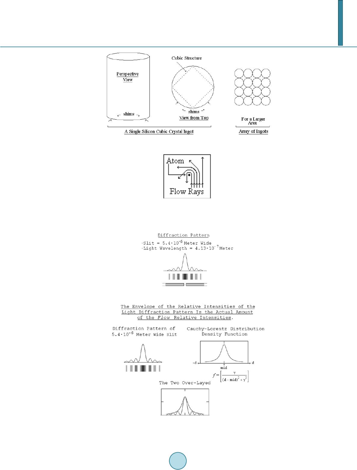 R. Ellman Figure 9. The Overall Deflector. Figure 10. Single Atom Deflection of Rays of Gravitational Flow. Figure 11. A Slit Light Diffraction Pattern. Figure 12. The Cauchy-Lorentz Distribution Diffraction Pattern En- velope.  R. Ellman diffraction pattern by the appropriate choice of value of its distribution parameter γ [Greek gamma]. The deflection angle, Φ, is the angle of deflection of the rays to any particular point on the diffraction pattern and of intensity per the Cauchy-Lorentz Distribution at that point. The interest here is not in the location of the light interference maxima and minima, but in the deflection an- gles the diffraction imposes on the Flow. However, calculation of the deflection angles to the minima provides a good indication of the amount of Flow deflection obtained over the overall diffraction pattern. Table 1 below presents that data for the 5.4 × 10⁻⁶ meters wide slit with incoming light of wavelength 4.13 × 10⁻⁷ meters. [The minimums are counted outward from the center peak of the diffraction interference pattern]. Sin(Φ) = n ∙ [light wavelength/slit width], n = 1, 2, ... Table 1 demonstrates that the deflection of the Flow is at least in amounts up to 90˚. That deflection may well extend to angles beyond 90˚. There is no way of determining that from the diffraction pattern. However, while the light of the diffraction pattern cannot be deflected beyond 90˚ in any case because the light cannot penetrate the material containing the slit, the Flow readily penetrates and permeates all of material reality. The tilt of the cubic crystal structure divides the slit into 1010 sub regions the first and last of which are at the slit’s edge and produce the maximum deflection. The tilt so arranges that ultimately all of the vertical compo- nents of the incoming vertical Flow must pass through one of those “at the edge of the slit” regions and must experience maximum deflection. The overall average effect is equivalent to every ray’s vertical component curving at least 90˚ because the crystal tilt causes every ray to pass extremely close to an atom at some point in the crystal, as the extreme rays in Figure 13, below. There does not appear to be any way to analyze, calculate, or evaluate in advance the overall deflection that is achieved other than by actual experiment. With the overall average effect equivalent to every ray’s vertical component curving 90˚, i.e. to the horizontal, the overall total net effect of the vertical components after deflec- tion is zero. Then the overall amount of deflection is 100% of the natural un-deflected gravitation reducing the gravitation to essentially zero. 7. Gravito-Electric Power Generation Gravito-electric power generation is similar to hydro-electric power generation in which the energy of water Table 1. Diffraction Minimums Deflection Angle. Minimum # Φ° Minimum # Φ° 1 4.39 8 37.72 2 8.80 9 43.50 3 13.26 10 49.89 4 17.81 11 57.28 5 22.48 12 66.60 6 27.36 13 83.86 7 32.37 14 Sin(Φ) > 1.0 Figure 13. Single Slit Gravitation Deflection.  R. Ellman falling in Earth’s gravitational field powers water-turbines that drive electric generators. In gravito-electric power, depicted schematically in Figure 14 below, a gravitation deflector makes the water in the central region of the mechanism lighter than that in the outer region, which is acted on by natural gravita- tion. The lighter reduced gravitation water floats up on the in-flow under it of the heavier natural gravitation water. The result is continuous circulation of the water, like a continuous waterfall. Water turbines like those used in hydro-electric plants can be placed in the gravito-electric continuous water flow to drive electric generators as in hydro-electric plants. 8. Practical Aspects—Design Engineering While the net gravitational field is vertically upward, i.e. radially outward from the Earth’s surface, local gravi- tation is radially outward from each particle of matter. As in Figure 15 below, a mass above the Earth’s surface receives rays of gravitational attraction from all over its surrounding surface and the underlying body of the Earth. The net effect of all of the rays’ horizontal components is their cancellation to zero. The net effect of all of the rays’ vertical components is Earth-radially-outward gravitation. 8.1. Gravitational Ray’s Horizontal and Vertical Components The net gravitational effect on objects is due to the vertical component of all of the myriad rays of gravitational field Flow at a wide variety of angles to the horizontal. This “components aspect” is valid because of the “com- ponents aspect” appearance in the “Gravitational Lensing” effect on cosmic light. The various rays of the Flow propagation from the individual particles of the gravitating body [for example the Earth] are from each individual particle of it to the selected point [above the gravitating body] on which their action is being evaluated. That is the point P in Figure 15 directly above the “A” at height h in the figure. The Earth’s gravitational action along a ray of Flow takes place from the Earth’s surface to deep within the Earth. The inverse square effect, that the strength of a Flow source is reduced as the square of the increase in the radial distance of it from the object acted upon, is exactly offset by that the number of such sources acting [per “ray” so to speak] increases as the square [non-inverse] of that same radial distance. That is, the volume, hence the number, of Flow sources for a ray of propagation at the object is contained in a conical volume, symmetri- cally around the ray with its apex at the object acted upon. Figure 14. A Gravito-Electric Generator. Figure 15. Rays of Gravitation from the Sur- roundings.  R. Ellman However, because the net gravitational effect is produced only by the vertical component of each ray of Flow propagation, the effectiveness of each ray is proportional to the Cosine of the angle between that ray and the perfectly vertical as the angle θ in Figu re 16, below. The actual total gravitational action includes all rays from θ = 0 through to θ = 90˚. That range would require an infinitely large deflector to act on all such rays, that is the deflector would have to be a disk of infinite radius. For lesser values of the maximum θ addressed, the portion of the total gravitation sources included is the integral of Cos θ∙dθ from θ = 0 to θ = Chosen Lesser Value. The integral of the cosine is the sine. Example lesser por- tions of the total gravitational action addressed as θ varies are presented in Table 2, below. The gravitational deflector as a disk beneath the Object to be levitated must extend horizontally far enough to intercept and deflect the Chosen Lesser Value of angle θ rays of gravitational wave Flow that are able to act on the Object of the deflection as depicted in Figure 17, below. For the perfectly vertically traveling rays of gravitation waves the required vertical distance that must be tra- veled within the cubic crystal is the previously presented 0.50 meters and 0 horizontal distance is traversed in so doing. But a ray at angle θ, in order to traverse the required 0.50 meters vertically, must traverse horizontally 0.50·Tan[θ] meters, at the same time. For θ more than 45˚ that can become quite large and the deflector likewise. Because the deflector disk must extend over a large area to deflect most of the gravitation, an alternative, and better, solution to the problem of rays of gravitation arriving over the range from θ = 0 to θ = 90˚ is to wrap the deflector up the sides of the Object to be levitated as Figure 18. In this configur ation the deflector takes up little more space than the Object levitated. However, the non-per- fectly vertical traveling rays must still travel within the cubic crystal the horizontal distance 0.50 ·Tan[θ] meters. That requires that the horizontal thickness of the vertical sides of the cup-shaped deflector must be of that 0.50·Tan[θ] meters thickness. Because the value of Sinθ and, therefore, the fraction of the total gravitational action, increases relatively little above θ = 60˚ whereas the value of Tan[θ] increases quite rapidly, from 1.7 to ∞ above θ = 60˚ that θ = 60˚ is the appropriate value to which to design. The thickness of the “walls” of the “cup” would then be 0.50·Tan[60˚] = 0.85 meters. The deflector would be only slightly larger than the Object levitated. Table 2. The Effect of θ. θ Sin θ = Fraction of Total Maximum Gravitational Action 0˚ 0.000 30˚ 0.500 45˚ 0.707 60˚ 0.866 Figure 16. The Angle θ. Figure 17. The Deflector as a Disk.  R. Ellman Figure 18. Cup-Shaped Deflector. 8.2. Gravitation Deflector Design Parameters The Deflector is a cup shaped array of monolithic Silicon cubic crystals. The crystals forming the flat “base” of the “cup” must be 0.50 meters in height. The “sides” of the “cup” will be the same kind of 0.50 meter crystals stacked and aligned vertically. The thickness of the “sides” must be 0.85 meters. The crystals are grown with circular cross-section and in diameters up to 0.30 meters; however, those cylin- drical pieces must then be machined to hexagonal or square cross section for a number of them to fit together with negligible open space. The cross-section area of these crystals is π∙d2/4 = 0.785·d2 before machining. For a circular deflector the configuration is poorly compatible with arranging the crystals in a close-fitting ar- ray unless it involves a large number of crystals each of small cross-section relative to the horizontal cross-sec- tion of the overall deflector. For that case the crystals should be machined to hexagonal cross-section. For smaller deflectors the configuration should be of rectangular cross-section and the crystals machined to square cross-section, Table 3. 8.2.1. Circular Cross-Section Gravitation Deflector Structure A circular cross-section gravitation deflector structure to provide deflection for an object of height, h, and di- ameter, d meters would have the Table 4 parameters. From the above the examples of Table 5 obtain. The 0.85 meters thickness of the “cup” “sides” requires 20 layers horizontally of 50.8 millimeters [2inch] crystals. 8.2.2. Square Cross-Section Gravitation Deflection Structure A square cross-section gravitation deflector structure to provide deflection for an object of square cross-section side, s, and height, h meters would have the parameters of Table 6. From the above the examples of Table 7 obtain. The 0.85 meter thickness of the “cup” “sides” requires 3 lay- ers horizontally of 300 millimeters [11.8 inch] crystals. Figure 19 depicts a resulting deflector. 8.3. Calibrating the Individual Silicon Crystals The individual crystals cannot be grown exactly identical to each other. In each the orientation of the long axis of the cubic crystal structure may vary minutely from each of the others. To find the optimum tilt and orientation for a single crystal the tilt must be varied over the range of possibili- ties while the effect from exactly below it is observed on a balance scale. But most of the effect of gravitation on a single crystal is not from exactly below it. The solution to that problem is to conduct the optimization atop a structure, that relying on the inverse square effect, effectively isolates the crystal from most of the gravitation from surrounding sources except that exactly below it—a high pedestal having a cross section comparable to that of the crystal, as in Figure 20. To conduct that calibration on thousands of crystals should not be necessary if a method can be developed to exactly measure the long axis orientation in any given crystal. The process can then determine the optimum ori- entation of the crystal tilt relative to the actual long axis of a few cubic crystals being calibrated. That same crystal tilt relative to the actual long axis can then be applied to each of the other crystals by means of appropri- ate shims once the particular long axis orientation of each has been exactly measured.  R. Ellman Table 3. Crystal Cross-Sections. Deflector Crystal Cross-Section Crystal Cross-Section Area Percent of Crystal Circular Hexagonal [√3/3]∙d2 = 0.577∙d2 73.5 Rectangular Square d2/2 = 0.500∙d2 63.7 Table 4. Round Deflector Parameters. Part Dimension Size Cup Sides Thickness, t 0.85 m Inside diameter, ID d Outside diameter, OD d + 2∙t = d + 1.7 Height h Height Layers h ÷ 0.5 Layer Area π∙[OD2 – ID2] ÷ 4 == 0.785∙[OD2 – ID2] Base Disk Thickness 1 crystal layer = 0.5 m Diameter d + 2∙t = d + 1.7 Area π∙[OD2 – ID2] ÷ 4 == 0.785∙[OD2 – ID2] Table 5. Example Round Deflectors. d h Cup Disk Base Cup Sides Total Volume Nr. of 2” Hex Crystals Area Volume Area Volume 1 1 5.72 5.75 4.94 4.94 10.7 13,280 10 10 131 1310 29 290 319 779,570 Table 6. Square Deflector Parameters. Part Dimension Size Cup Sides Thickness, t 0.85 m Square inside, IS s Square outside, OS s + 2∙t = s + 1.7 Height h Height Layers h ÷ 0.5 Layer Area OS2 – IS2 Base Square Thickness 1 crystal layer = 0.5 m Side s + 2∙t = s + 1.7 Area [s + 2∙t]2 = [s + 1.7∙t]2 Table 7. Example Square Deflectors. s h Cup Disk Base Cup Sides Total Volume Nr. of 11.8” Square Crystals Area Volume Area Volume 1 1 7.3 7.3 6.3 6.3 13.6 195 10 10 137 1370 36.9 369 1,739 2,486  R. Ellman Figure 19. Highly Schematic Depiction of a Rectangular Gravitation Deflector. Figure 20. Crystal Calibration. 8.4. Alternative to Calibration Monolithic silicon cubic crystals are commercially available with the ends nearly a single plane, that is within 0.2 degrees of the (100) plane of the cubic structure. In view of the various effects analyzed in Appendix C to the book, Gravitics—The Physics of the Behavior and Control of Gravitation, and their resolution in its section The Random Distribution Solution to The Crystal Tilt [2], that amount or moderately more of inaccuracy in the crystal tilt is of no significance except that it potentially may call for crystal thicknesses moderately greater than 0.5 m. The task, then, is research and development to better optimize the design so that practical implementation can begin See the references [1-3], below, for the detailed development of mass, field, gravitation, the flow, the expo- nential decay and the time constant. References [1] Ellman, R. (2004) The Origin and Its Meaning. 2nd Edition, The-Origin Foundation, Inc., Santa Rosa. [2] Ellman, R. (2008) Gravitics—The Physics of the Behavior and Control of Gravitation. 2nd Edition, The-Origin Foun- dation, Inc., Santa Rosa. [3] Ellman, R. (2011) Gravito-Electric Power Generation. US Patent No. 13/199,867.
|