Journal of Power and Energy Engineering, 2014, 2, 694-703
Published Online April 2014 in SciRes. http://www.scirp.org/journal/jpee
http://dx.doi.org/10.4236/jpee.2014.24093
How to cite this paper: Blumschein, J., Yelgin, Y. And Kereit, M. (2014) Blackout Prevention by Power Swing Detection and
Out-of-Step Protection. Journal of Power and Energy Engineering, 2, 694-703. http://dx.doi.org/10.4236/jpee.2014.24093
Blackout Prevention by Power Swing
Detection and Out-of-Step Protection
J. Blumschein, Y. Yelgin, M. Kereit
Infrastructure & Cities Sector, Siemens AG, Munich, Ger ma ny
Email: joerg.blumschein@siemens.com
Received December 2013
Abstract
Power swing evoked by sudden changes like faults or switching operations will become more and
more important for protective relaying, due to the growing load flow in electrical power networks.
Unwanted trips of the distance protection function must be avoided to prevent cascading effects
and blackouts in the network. Selective out-of-step-tripping is required to stop unstable power
swing and to prevent damage to affected generators. Therefore a reliable method for detection of
power swing is presented, which requires no settings for operation. Power swing can be detected
from 0.1 Hz up to 10 Hz swing frequency, also during open pole condition and during asymmetric-
al operation. A blocking logic prevents unselective trips by the distance protection. However,
faults that occur during a power swing must be detected and cleared with a high degree of selec-
tivity and dependability. For unstable power swing a flexible out of step tripping function will be
proposed. The coordination of power swing detection, distance protection and out of step protec-
tion provides a reliable system protection.
Keywords
Power Swing Detection; Distance Protection; Out of Step Prot ecti on
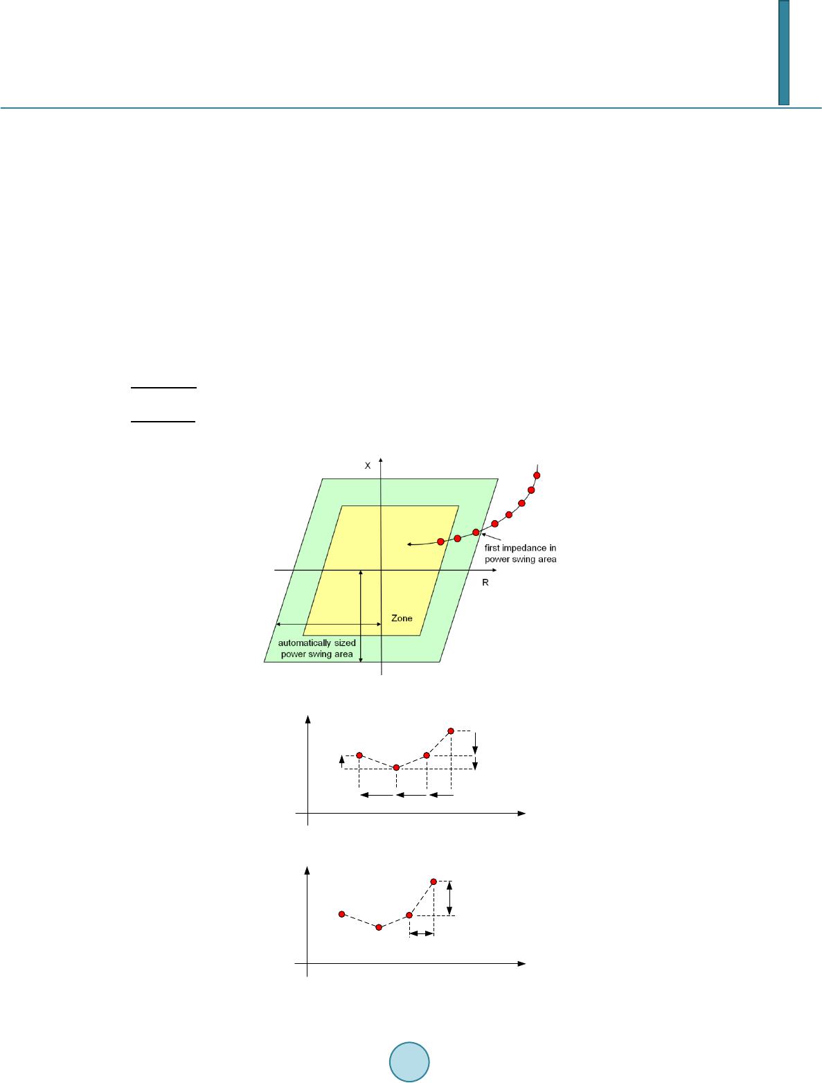
1. Power-Swing-Detection Algorithm Based on Continous Impedance Calculation
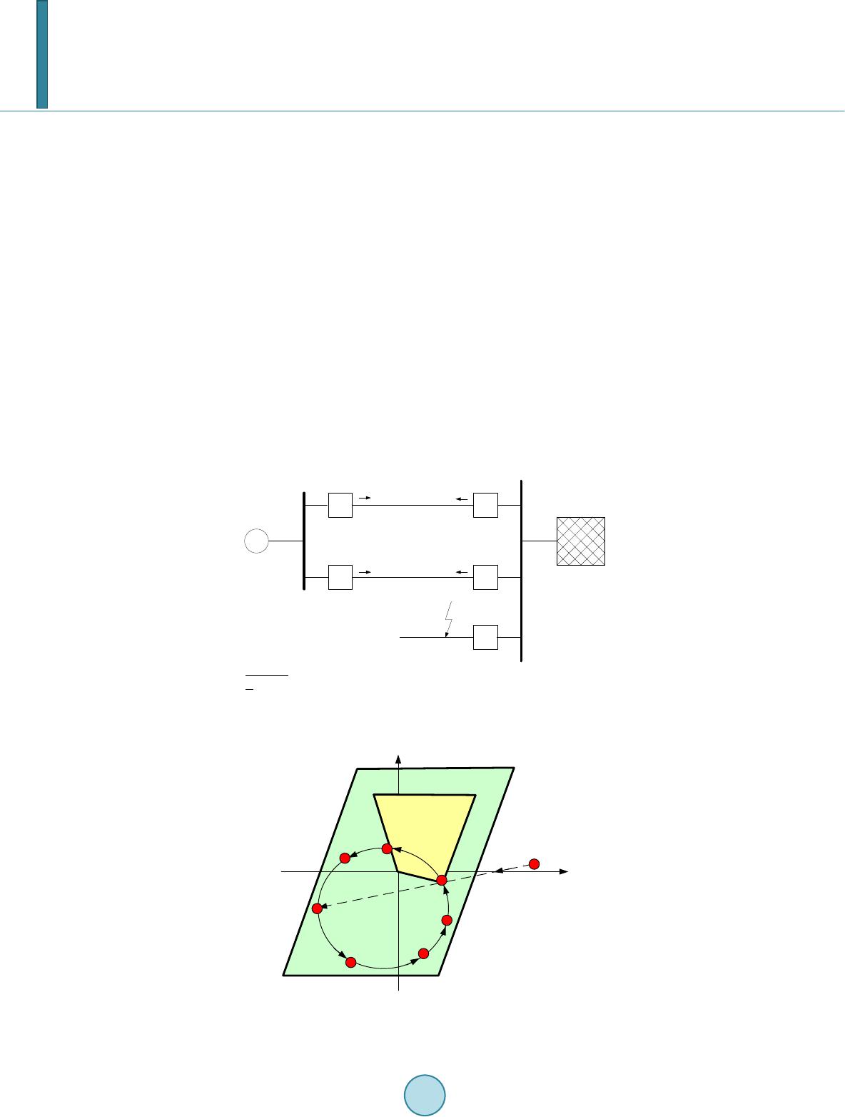
Classical power swing detection methods based on concentric characteristic or blinders need a sophisticated grid
study to determine the correct settings. The settings are fixed and will not adapt to any changed system condition.
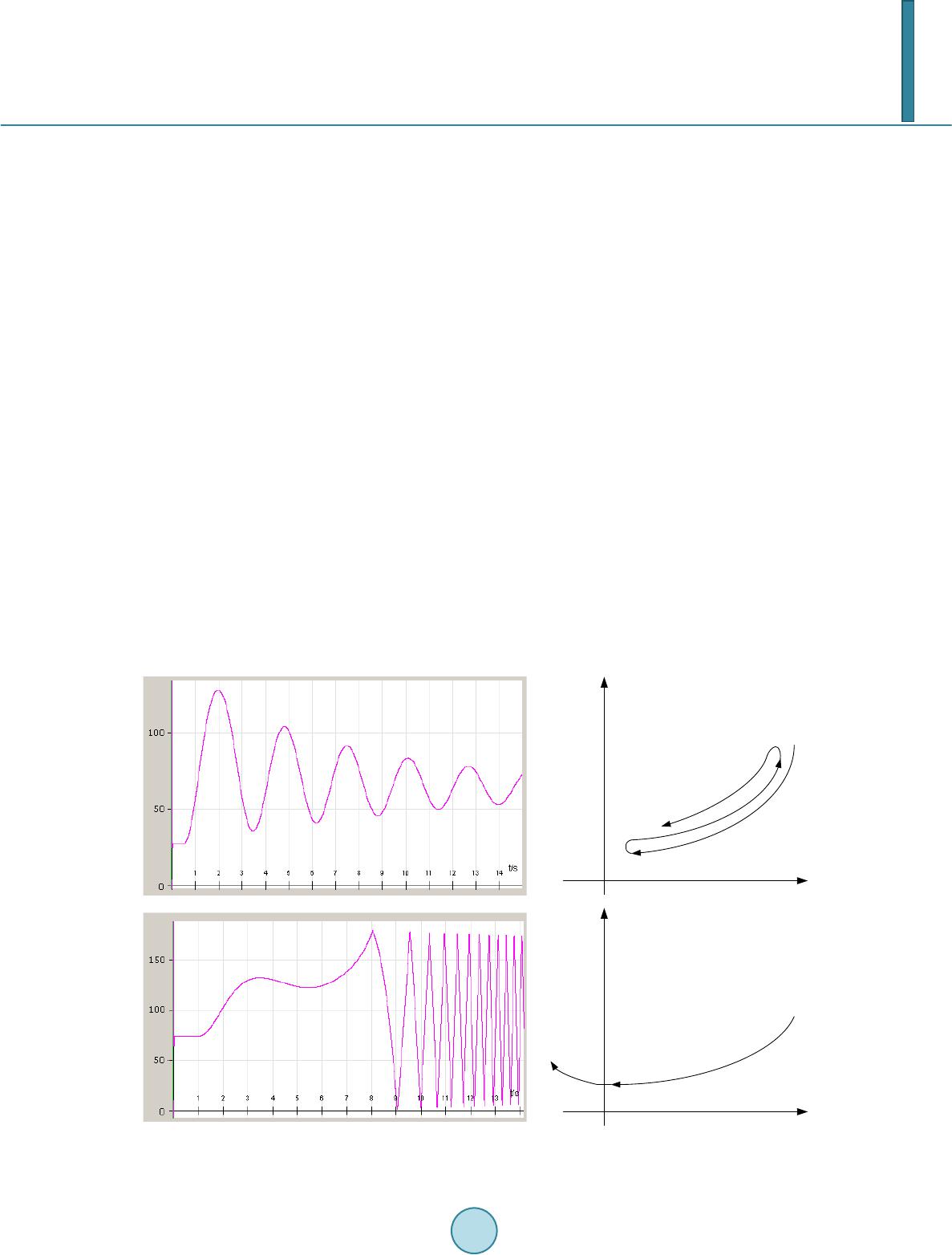
If the grid study does not consider the worst case, then the appearance of a power swing or out of step condition
could lead to a maloperation.
Also the assumption that a power swing is always a symmetrical phenomenon and any asymmetrical current
(or voltage) can be used for releasing the distance protection function is not fulfilled in a complex application. A
proper power swing detection function has to perform also during these conditions.
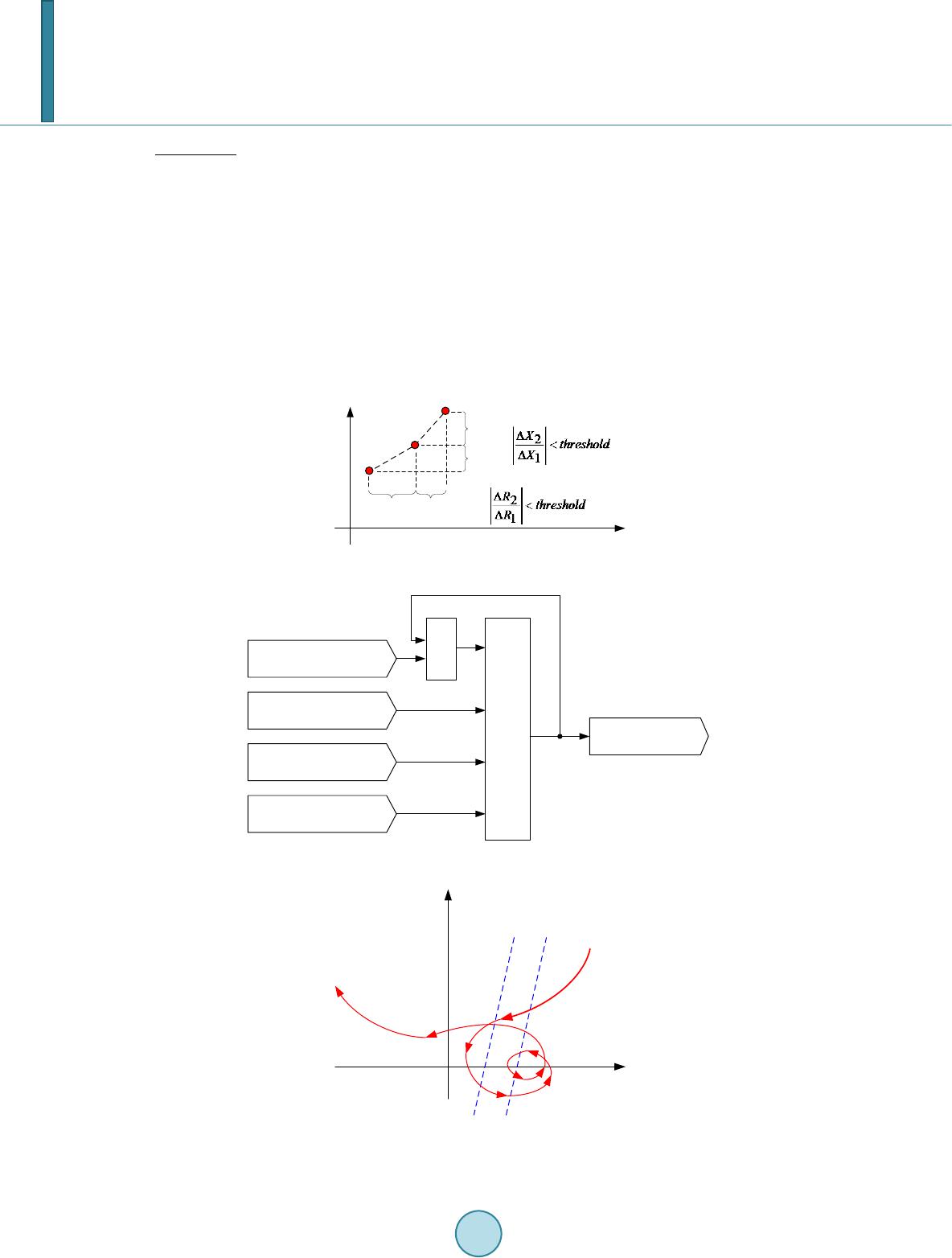
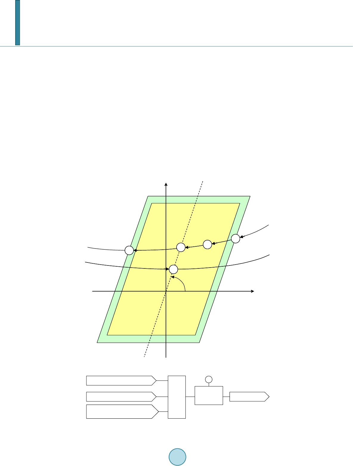
The following method described below solves these problems. It is based on a continuous impedance calcula-
tion [4]. This method has the following features:
No settings are required, thus no complex calculation is needed.
Detection of power swing with frequencies from 0.1 Hz up to 10 Hz.
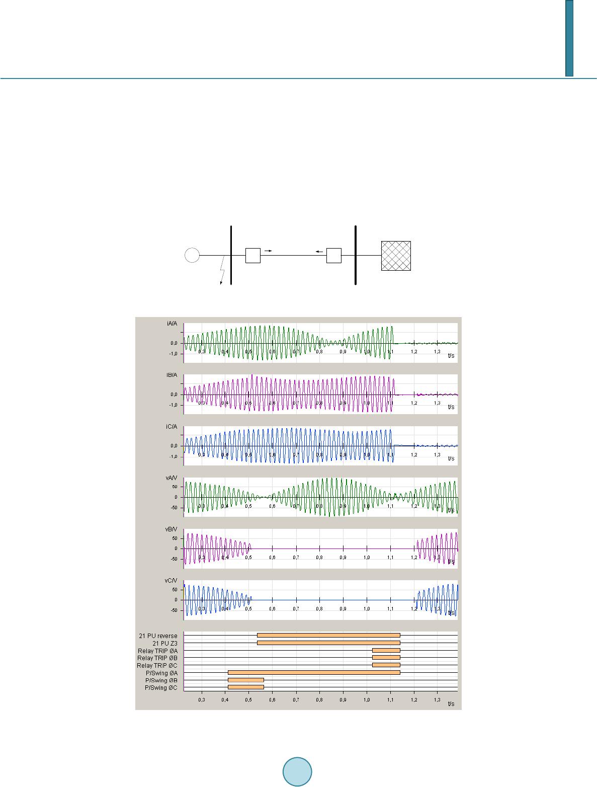
Detection of power swing that occur during single-pole open condition and during faults.
J. Blumschein et al.
695
Unblocking of distance protection on all kind of faults occurring during power swing.
Out-of-step tripping in case of unstable power swing.
The power swing detection function is based on continuous impedance calculations. The impedances are mo-
nitored continuously four times per cycle of the power system frequency for each phase separately. During
power swing condition these vectors move on an elliptical path. When the impedance vector of at least one
phase enters the power swing area, as shown in Figure 1, the power swing algorithm starts to analyze each im-
pedance trajectory separately. The power swing area will be calculated automatically so that no settings are
needed.
If a power swing is detected, the power swing detection will stay active, even if the impedance vector leaves
the power swing area. It will drop off in case of a power system fault of if the system turns back to normal load
condition.
The algorithm calculates new R and X values for each phase and compares them with the history (memorized
values). The main criteria, which are used to detect a power swing, are monotony, continuity and smoothness.
The applied thresholds are calculated dynamically. This automatic adaptation to the change of the trajectory
speed enables the function to detect low frequency power swing as well as high frequency power swing.
Monotony: The directions of the derivates of R and X will be evaluated. To guarantee a directional move at
least one of them should not change the direction (Figure 2).
Continuit y: The distance between two R or X values has to exceed a threshold. This ensures that the imped-
ance vector is not stationary (Figure 3).
Figure 1. Automatically sized power swing area.
Figure 2. Monotony criterion.
Figure 3. Continuity criterion.
X
R
ΔX
2
ΔR
1
ΔR
2
ΔX
1
ΔR
3
ΔX
3
ΔR
R
ΔX
X
J. Blumschein et al.
696
Smoothness: The ratio of two successive differences of R or X has to be below a limit. This ensures that the
impedance locus has a uniform movement with no abrupt changes (Figure 4).
These criteria are fulfilled only during power swing condition. Neither during load condition nor during faults,
the impedance vector moves smoothly along an orderly path. During faults, the impedance vectors jump imme-
diately to a fault impedance. During load condition, the impedance vectors usually do not move.
The logic in Figure 5 is used to ensure stable and secure operation of the power swing detection without
risking unwanted power swing blocking during fault s.
In reality the impedance trajectories will not follow a perfect elliptical path. Figure 6 shows an idealized im-
pedance trajectory for a power swing with three machines oscillating against each other.
It is obvious that such impedance trajectories will be difficult to manage if static thresholds like blinders are
used. The above mentioned criteria are able to detect power swing for this kind of impedance trajectory.
Another challenge is to detect stable power swing with low frequency. Figure 7 describes how the velocity of
the impedance vector changes during a stable power swing.
Figure 4. Smoothness criterion.
impedance in power
swing area
AND
monotony
continuity
smoothness
power swing
detected
OR
Figure 5. Logic for power swing detection.
Figure 6. Impedance trajectory for 3-machine power
swi n g .
R
ΔR
1
ΔX
1
ΔR
2
ΔX
2
X
X
R
difficult to manage
with blinders
J. Blumschein et al.
697
Figure 7. Impedance trajectory during stable power swing.
At the beginning of the power swing, the impedance vectors move quite quickly. The velocity of the imped-
ance vectors decreases, until they reach the point of return. At the point of return the velocity of the impedance
vectors is very low, nearly zero. After passing the point of return, the impedance vectors move with increasing
velocity.
At the point of return it looks like a three-phase fault, because all impedance vectors are in the zone with
nearly no change. To distinguish between three-phase faults and stable power swing with low frequencies a time
delay is used. The delay is calculated dynamically and depends on the velocity of the impedance vectors.
2. Selectivity of Distance Protection during Power Swing
To maintain the stability of the power system and to prevent cascading effects a selective tripping of a fault is
very important, more than ever under power swing conditions.
The selectivity of a distance protection device is dependent on the following characteristics:
Determination of the faulted loops (loop selection)
Determination of the direction to the fault
Measurement of the distance to the fault
Loop selection and directional measurement must work in different ways under steady state or power swing
condition to get the best results.
Normally a distance protection device with a polygonal tripping characteristic detects the faulted loops by
checking which of the six loop impedances ZAG, ZBG, ZCG, ZAB, ZBC, and ZCA are within one of the tripping
zones. An additional logic guarantees the correct loop selection even in difficult situations, when not only
faulted loop impedances are within the tripping zones (see also [1]-[4]).
Under power swing condition these measures are not sufficient to prevent unselective trips, because the impe-
dance vectors of the unfaulted loops will also move into the tripping zones and even the phase angles between
the impedances will give no information about the type of fault. A phase selective and reliable power swing de-
tection is necessary to find out the correct type of fault.
3. Determination of the Faulted Loops under Power Swing Condition
A correct determination of the faulted loops is obligatory for a distance protection relay. A selection of a non-
faulted loop for the distance measurement could result either in an unwanted trip in case of an external fault or
the absence of a necessary trip. Under steady state conditions the loop selection is no problem for modern dis-
tance protection relays. The location of the impedance vectors in the impedance plane and the voltage and cur-
rent phasors give enough information about the type of fault. Under power swing conditions the loop selection is
much more difficult: The impedance vectors of the unfaulted loops may be located within the tripping zone and
the voltage and current phasors don’t indicate the faulted loops. A reliable and phase selective power swing de-
tection is necessary to get the faulted loops under power swing conditions. Figure 8 shows a network with an
internal fault in B-G. Figure 9 shows the related fault recording from the distance protection relay D1.
Zone
X
R
point of
return
decreasing
velocity
increasing
velocity
J. Blumschein et al.
698
Figure 8. Internal fault B-G during a power swing.
Figure 9. Internal fault B-G with single pole trip during a power swing.
Before the fault begins a power swing is detected in all phases. After the fault inception, only the power swing
detection for the faulted phase B is dropped off. As can be seen in the binary output signals from the relay, a
pickup-signal is also generated for the non faulted loops. The fault occurs nearly at this time, when the phase
currents reached their maximum value due to the power swing. The phase currents of the unfaulted phases have
nearly the same magnitude than the current of the faulted phase. Standard phase selection methods will not work
under these conditions. The power swing detection for the phases A and C will block a trip-signal signal for all
loops except the faulted loop B-G. With this additional information a single pole trip including an auto reclosing
cycle is possible instead of a definite three pole trip command.
J. Blumschein et al.
699
4. Determination of the Direction to the Fault
During a power swing the frequency of the voltage is permanently changing. Therefore the phase angle of the
stored voltage phasors cannot be matched to the actual phasing. The un-faulted voltage (cross polarization) is
also not valid for the direction measurement during power swing.
The actual faulted loop voltage provides a correct direction decision, but during close in forward faults and
reverse busbar faults this voltage is zero or approximately zero. For this reason the voltage of the actual faulted
loop cannot be used in all cases. In this case, the negative sequence direction measurement is applied.
Contrary to the standard measurement methods the negative sequence impedance is not affected by the power
swing so that it indicates the correct direction. Figure 10 shows a network with an external fault in BC-G. Fig-
ure 11 shows the related fault recording from the distance protection relay D1.
BC-G
D1 D2
~
G
Figure 10. External fault in BC-G during a power swing.
Figure 11. Example of a reverse busbar fault during power swing.
J. Blumschein et al.
700
The impedance vectors of the phases B and C stop moving after fault inception. This leads to a drop off of the
power swing blocking in phases B and C because of the continuity criterion. Due to the fact that the fault is in
reverse direction, the protection relay D1 doesn’t trip immediately. The relay recognizes a fault in reserve direc-
tion and expects a trip signal from another relay that is primarily responsible for that area. If the fault is not
cleared, the backup protection of the relay D1 will trip after the grading time for reverse faults expired, which is
also displayed in Figure 11.
With the negative sequence direction determination it is not possible to determine the direction of each meas-
ured loop separately. For this reason, the negative sequence direction check should only be used under power
swing condition.
The power swing detection is not only needed to generate blocking signals, it can be also used to adapt pro-
tection functions to the actual state of the network. One example for such an adaptive protection function is the
directional check for the distance protection.
5. Backup-Protection for 3-Phase Faults during Power Swing
Another challenge is to ensure backup distance protection for 3-phase -faults during power swing. Figure 12 de-
scribes a simplified network scheme from [3], where a 3-phase -fault on an external radial feeder occurred. A
power swing is evoked as a result of the fact that the protection relay A did not trip on time.
Figure 13 illustrates the impedance trajectory of a phase to phase loop after fault inception by the distance
protection relay D4. The impedance trajectories for the other distance protection relays are similar.
3-Phase
Fault
D1
D3
D2
D4
~
G
A
D1 .. D4: Distance protection relays
A: Protection relay for a single feeder
Figure 12. Power swing due to a 3-phase-fault. Simplified network
scheme from [3].
Figure 13. Impedance trajectory of a phase-phase-loop
after fault inception.
Z2
Z1
Load
Impedance
X
R
Fault
Impedance
J. Blumschein et al.
701
After fault inception the impedance vector jumps from the load impedance to the fault impedance. The dis-
tance protection relay D4 measures a 3-pha se-fault in Zone Z2 and does not trip immediately. Due to the fact
that the protection relay A did not trip on time, a power swing is evoked. As a result of the continuing power
swing, the impedance vector moves on an elliptical trajectory and crosses the Zone Z1. To avoid an unselective
trip in Zone Z1, a special logic is applied. This logic releases only zones for which a pickup was recognized be-
fore the power swing is detected.
6. Out of Step Tripping
A sudden change of load in the power system caused by a fault, by disconnection of loaded lines or automatic
reclosing forces the generators to adjust to this new load condition. The adjustment will not be instantaneous due
to the mass of the generators, but rather in the form of oscillations, which is shown in Figure 14. Normally it
will be a damped oscillation. The generators will be able to return to a normal steady state condition. In some
cases the generators loose synchronism and run out of step. This situation can lead to a blackout of the whole
grid .
During an out of step condition a trip of certain transmission lines can separate the unstable grid into sub grids
with the goal to reach stability in these sub grids. The out of step protection has to distinguish between a stable
power swing, where the system recovers and an unstable out of step condition. A trip is only required for the un-
stable out of step condition.
According to the network structure the out of step trip can be issued at different severity of the out of step
condition.
In a strong network it can be advantageous to trip as fast as possible if the relay detects an out of step condi-
tion. In a weak network however a fast trip in case of out of step condition can lead to a blackout. Here it can be
adva nta geous to keep the line in service as long as possible.
For that reason the out of step protection generates basic signals, which can be logically combined to generate
the trip signal.
Figure 15 illustrates the following basic signals:
Figure 14. Rotor angle and impedance trajectories for stable and unstable power swing.
X
R
X
R
Rotor angle for
stable power swing
Rotor angle for
unstable power swing
J. Blumschein et al.
702
1) impedance in out of step area detected
2) power swing detected
3) impedance crosses the line angle from the right side
4) impedance leaves power swing area at opposite side after complete crossi ng
5) impedance crosses the line angle from the left side
For standard applications the out of step protection will trip if the impedance leaves the power swing area at
opposite side after complete crossing (4). A fast trip for out of step protection is possible if the impedance
crosses the line angle at (3) or (5).
With a flexible combination of these basic signals it is possible to generate an individual out of step trip. Fig-
ure 16 shows special out of step logic which trips only if the power swing impedance crosses the line angle in-
side a predefined out of step area 3 times from the right side.
For the protection of the transmission systems of the future we recommend a strong coordination of power
swing detection, distance protection and out of step protection.
This method, successfully used in Kazakhstan and Romania has the following advantages:
1) distance protection for selective clearing of faults in the protected zone.
2) block distance protection in case of power swing.
3) flexible out of step protection to split the grid selectively according grid study.
222
333
555
444
X
R
α
111
Figure 15. Basic signals for out of step detection.
impedance crosses line angle
from the right side
impedance in out of step area
Power swing detectedAND
COUNTER
3
Out of Step Trip
Figure 16. Logic for special out of step tripping.
J. Blumschein et al.
703
4) optimal coordination of distance protection and out of step protection by using the same algorithm for power
swing detection.
References
[1] Si emens, A.G., Infrastructure & Cities Sector (2006) User Manual Distance Protection 7SA522 V4.61. Ordering Nr.
C53000-G1176-C155-5. http://www.siprotec.com
[2] Sch maranz, R., Renner, H. a nd Hübl, I. (2007) Rotor Angle Stability and the Effects on Protection Devices in Distribu-
tion Networks. KELAG, Klagenfurt, Austria and University of Technology, Graz, Austria. 19th International Confe-
rence on Electricity Distribution, Vienna, 21 May 2007. http://www.ove.at/akademie/cired07.htmT
[3] Juri sch, A. and Sch wenke, M. (2000) Method of Deriving a Signal Ind icating an Oscillation in an Electric Power
Supply System. US -Patent 6104182.
[4] Juri sch, A. and Kereit, M. (20 00) Process for Producing Signals Identifying Faulty Loops in a Polyphase Electrical
Power Supply Network. US-Patent 6034592.