Paper Menu >>
Journal Menu >>
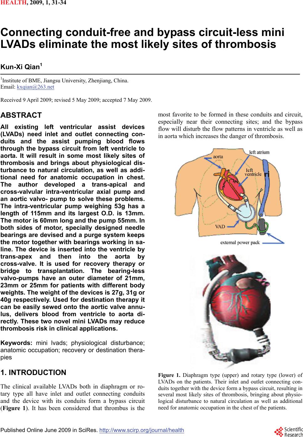 HEALTH, 20 09, 1, 31-34 Published Online June 2009 in SciRes. http://www.scirp.org/journal/health Connecting conduit-free and bypass circuit-less mini LVADs eliminate the most likely sites of thrombosis Kun-Xi Qian1 1Institute of BME, Jiangsu University, Zhenjiang, China. Email: kxqian@263.net Received 9 April 2009; revised 5 May 2009; accepted 7 May 2009. ABSTRACT All existing left ventricular assist devices (LVADs) need inlet and outlet connecting con- duits and the assist pumping blood flows through the bypass circuit from left ventricle to aorta. It will result in some most likely sites of thrombosis and brings about physiological dis- turbance to natural circulation, as well as addi- tional need for anatomic occupation in chest. The author developed a trans-apical and cross-valvular intra-ventricular axial pump and an aortic valvo- pump to solve these problems. The intra-ventricular pump weighing 53g has a length of 115mm and its largest O.D. is 13mm. The motor is 60mm long and the pump 55mm. In both sides of motor, specially designed needle bearings are devised and a purge system keeps the motor together with bearings working in sa- line. The device is inserted into the ventricle by trans-apex and then into the aorta by cross-valve. It is used for recovery therapy or bridge to transplantation. The bearing-less valvo-pumps have an outer diameter of 21mm, 23mm or 25mm for patients with different body weights. The weight of the devices is 27g, 31g or 40g respectively. Used for destination therapy it can be easily sewed onto the aortic valve annu- lus, delivers blood from ventricle to aorta di- rectly. These two novel mini LVADs may reduce thrombosis risk in clinical applications. Keywords: mini lvads; physiological disturbance; anatomic occupation; recovery or destination thera- pies 1. INTRODUCTION The clinical available LVADs both in diaphragm or ro- tary type all have inlet and outlet connecting conduits and the device with its conduits form a bypass circuit (Figure 1). It has been considered that thrombus is the most favorite to be formed in these conduits and circuit, especially near their connecting sites; and the bypass flow will disturb the flow patterns in ventricle as well as in aorta which increases the danger of thrombosis. Figure 1. Diaphragm type (upper) and rotary type (lower) of LVADs on the patients. Their inlet and outlet connecting con- duits together with the device form a bypass circuit, resulting in several most likely sites of thrombosis, bringing about physio- logical disturbance to natural circulation as well as additional need for anatomic occupation in the chest of the patients. 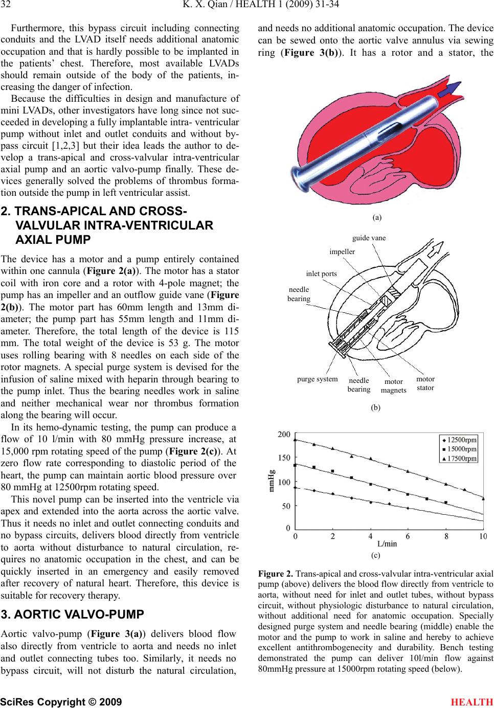 32 K. X. Qian / HEALTH 1 (2009) 31-34 SciRes Copyright © 2009 HEALTH Furthermore, this bypass circuit including connecting conduits and the LVAD itself needs additional anatomic occupation and that is hardly possible to be implanted in the patients’ chest. Therefore, most available LVADs should remain outside of the body of the patients, in- creasing the danger of infection. Because the difficulties in design and manufacture of mini LVADs, other investigators have long since not suc- ceeded in developing a fully implantable intra- ventricular pump without inlet and outlet conduits and without by- pass circuit [1,2,3] but their idea leads the author to de- velop a trans-apical and cross-valvular intra-ventricular axial pump and an aortic valvo-pump finally. These de- vices generally solved the problems of thrombus forma- tion outside the pump in left ventricular assist. 2. TRANS-APICAL AND CROSS- VALVULAR INTRA-VENTRICULAR AXIAL PUMP The device has a motor and a pump entirely contained within one cannula (Figure 2(a)). The motor has a stator coil with iron core and a rotor with 4-pole magnet; the pump has an impeller and an outflow guide vane (Figure 2(b)). The motor part has 60mm length and 13mm di- ameter; the pump part has 55mm length and 11mm di- ameter. Therefore, the total length of the device is 115 mm. The total weight of the device is 53 g. The motor uses rolling bearing with 8 needles on each side of the rotor magnets. A special purge system is devised for the infusion of saline mixed with heparin through bearing to the pump inlet. Thus the bearing needles work in saline and neither mechanical wear nor thrombus formation along the bearing will occur. In its hemo-dynamic testing, the pump can produce a flow of 10 l/min with 80 mmHg pressure increase, at 15,000 rpm rotating speed of the pump (Figure 2(c)). At zero flow rate corresponding to diastolic period of the heart, the pump can maintain aortic blood pressure over 80 mmHg at 12500rpm rotating speed. This novel pump can be inserted into the ventricle via apex and extended into the aorta across the aortic valve. Thus it needs no inlet and outlet connecting conduits and no bypass circuits, delivers blood directly from ventricle to aorta without disturbance to natural circulation, re- quires no anatomic occupation in the chest, and can be quickly inserted in an emergency and easily removed after recovery of natural heart. Therefore, this device is suitable for recovery therapy. 3. AORTIC VALVO-PUMP Aortic valvo-pump (Figure 3(a)) delivers blood flow also directly from ventricle to aorta and needs no inlet and outlet connecting tubes too. Similarly, it needs no bypass circuit, will not disturb the natural circulation, and needs no additional anatomic occupation. The device can be sewed onto the aortic valve annulus via sewing ring (Figure 3(b)). It has a rotor and a stator, the (a) guide vane impeller inslet port needle bearing (b) (c) Figure 2. Trans-apical and cross-valvular intra-ventricular axial pump (above) delivers the blood flow directly from ventricle to aorta, without need for inlet and outlet tubes, without bypass circuit, without physiologic disturbance to natural circulation, without additional need for anatomic occupation. Specially designed purge system and needle bearing (middle) enable the motor and the pump to work in saline and hereby to achieve excellent antithrombogenecity and durability. Bench testing demonstrated the pump can deliver 10l/min flow against 80mmHg pressure at 15000rpm rotating speed (below). purge systemmotor stato r needle bearing motor magnets 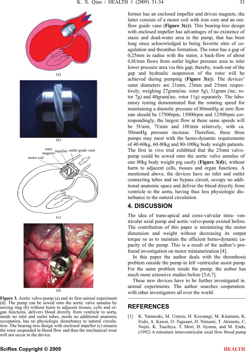 K. X. Qian / HEALTH 1 (2009) 31-34 33 SciRes Copyright © 2009 HEALTH (a) (b) (c) (d) Figure 3. Aortic valvo-pump (a) and its first animal experiment (d). The pump can be sewed onto the aortic valve annulus by sewing ring (b) without harm to adjacent tissues, cells and or- gan functions, delivers blood directly from ventricle to aorta, needs no inlet and outlet tubes, needs no additional anatomic occupation, has no physiologic disturbance to natural circula- tion. The bearing-less design with enclosed impeller (c) ensures the rotor suspended in blood flow and thus the mechanical wear will not occur in the device. former has an enclosed impeller and driven magnets, the latter consists of a motor coil with iron core and an out- flow guide vane (Figure 3(c)). This bearing-less design with enclosed impeller has advantages of no existence of stasis and dead-water area in the pump, that has been long since acknowledged to being favorite sites of co- agulation and thrombus formation. The rotor has a gap of 0,25mm in radius with the stator, a back-flow of about 0,8l/min flows from outlet higher pressure area to inlet lower pressure area via this gap; thereby, wash-out of the gap and hydraulic suspension of the rotor will be achieved during pumping (Figure 3(c)). The devices’ outer diameters are 21mm, 23mm and 25mm respec- tively, weighing 27gram(inc. rotor 5g), 31gram (inc. ro- tor 7g) and 40gram(inc. rotor 11g) separately. The labo- ratory testing demonstrated that the rotating speed for maintaining a diastolic pressure of 80mmHg at zero flow rate should be 17500rpm, 15000rpm and 12500rpm cor- respondingly, the largest flow at these same speeds will be 5l/min, 7l/min and 10l/min relatively, with ca. 50mmHg pressure increase. Therefore, these three pumps may meet with the hemo-dynamic requirements of 40-60kg, 60-80kg and 80-100kg body weight patients. The first in vivo trial exhibited that the 25mm valvo- pump could be sewed onto the aortic valve annulus of one 80kg body weight pig easily (Figure 3(d)), without harm to adjacent cells, tissues and organ functions. A mentioned above, the devices have no inlet and outlet connecting tubes and no bypass circuit, occupy no addi- tional anatomic space and deliver the blood directly from ventricle to the aorta, having thus less physiologic dis- turbance to the natural circulation. 4. DISCUSSION The idea of trans-apical and cross-valvular intra- ven- tricular axial pump and aortic valvo-pump existed before. The contribution of this paper is minimizing the motor dimension and weight without decreasing its output torque so as to maintain the efficient hemo-dynamic ca- pacity of the pump. This is a result of the author’s pro- found investigation on motor miniaturization [4]. In this paper the author deals with the thrombosis problem outside the pump in left ventricular assist pump. For the same problem inside the pump, the author has much more extensive studies before [5,6,7]. These new devices have to be further investigated in animal experiments. The author searches cooperation with other investigators all over the world. REFERENCES [1] K. Yamazaki, M. Umezu, H. Koyanagi, M. Kitamura, K. Eishi, A. Kawai, O. Tagusari, H. Niinami, T. Akimoto, C. Nojiri, K. Tsuchiya, T. Mori, H. Iiyama, and M. Endo, (1992) A miniature intraventricular axial flow blood pump motor coil roto r ma g nets im p elle r outlet g uide vane  34 K. X. Qian / HEALTH 1 (2009) 31-34 SciRes Copyright © 2009 HEALTH that is introduced through the left ventricular apex, Trans ASAIO, 38, 679-683. [2] H. Mitamura, H. Nakamura, E. Okamoto, R. Yozu, S. Kawada, and D. W. Kim, (1999) Development of the valvo pump: An axial flow pump implanted at the heart valve position, Artificial Organs, 23(6), 566. [3] G. Li, H. Zhao, X. Zhu, and B. Ren, (2002) Preliminary in vivo study of an intra-aortic impeller pump driven by an extracorporeal whirling magnet, Artif Organs, 26(10), 890. [4] K. X. Qian, H. Y. Yuan, W. M. Ru, and P. Zeng, (2002) Experimental method to reveal the effect of rotor mag- net size and air-gap on artificial heart driving motor torque and efficiency, J Med. Eng. Tech. 26(5), 199-201. [5] K. X. Qian, (2001) Axial reciprocation of rotating impel- ler: a new concept of antithrombogenecity in centrifugal pump, Journal of Medical Engineering & Technology, 25(1), 25-27. [6] K. X. Qian, P. Zeng, W. M. Ru, H. Y. Yuan, (2003) A novel permanent maglev impeller TAH: Most requirements on blood pumps have been satisfied, Journal of Biomaterials Applications, 18(1), 53-61. [7] K. X. Qian, (1990) Haemodynamic approach to reducing thrombosis and haemolysis in an impeller pump, J Biomed Eng., 12(6), 533-535. |