 Journal of Power and Energy Engineering, 2014, 2, 616-623 Published Online April 2014 in SciRes. http://www.scirp.org/journal/jpee http://dx.doi.org/10.4236/jpee.2014.24083 How to cite this paper: Liu, X.M. and He, Z.Y. (2014) Transmission Lines Distance Protection Using Differential Equation Algorithm and Hilbert-Huang Transform. Journal of Power and Energy Engineering, 2, 616-623. http://dx.doi.org/10.4236/jpee.2014.24083 Transmission Lines Distance Protection Using Differential Equation Algorithm and Hilbert-Huang Transform Xingmao Liu, Zhengyou He School of Electrical Engineering, Southwest Jiaotong University, Chengdu, China Email: liuxingmao1@gmail.com Received December 2013 Abstract This paper proposed the scheme of transmission lines distance protection based on differential equation algorithms (DEA) and Hilbert-Huang transform (HHT). The measured impedance based on EDA is affected by various factors, such as the distributed capacitance, the transient response chara cte ris tics of current transformer and voltage transformer, etc. In order to overcome this problem, the proposed scheme applies HHT to improve the apparent impedance estimated by DEA. Empirical mode decompos ition ( E MD) is used to decompose the data set from DEA into the intrin- sic mode functions (IMF ) and the residue. This residue has monotonic trend and is used to eva- luate the impedance of faulty line. Simulation results show that the proposed scheme improves significantly the accuracy of the estimated impedance. Keywords Hilbert-Huang T ra nsf orm ; Differential Equation Algorithm; Distance Prot ecti on ; Transmission Lines 1. Introduction Transmission lines are responsible for delivering a mass of energy from generator plants to load centers. Due to covering long distance outdoor, those lines have the highest fault rate in the power network. After faults occur- ring, they must be cleared immediately to decrease the disturbance the faults will impose on the power system. Distance protection is one of the most used protective principles for transmission lines. The traditional dis- tance relays which have been widely applied to transmission line calculate the impedance to the fault using the fundamental frequency component of the local voltage and local current [1] [2]. However, the operation time of these relays is at least one cycle and their performance can be affected by current transformer saturation, expo- nentially decaying current component (dc offset), etc. The travelling wave distance protections can achieve ultra high speed operation time [3], while their reliability needs to be improved further. Unlike above protections, the differential equation algorithm (DEA) based distance protection can operate within 6 - 8 ms after fault occurring [4]. This algorithm is not affected by dc offset and can make tripping decision before current transformer satura-  X. M. Liu, Z. Y. He tion [5]. Therefore, DEA is a promising distance relaying algorithm for transmission lines where faster operation time is required. However, affected by various factors, such as the transient response characteristics of voltage transformer and current transformer, the distributed capacitance, etc, the result of DEA fluctuates up and down around the actual value frequently after a fault occurring [6]-[8]. The direct using of the result calculated from DEA might lead to mal -opera tio n of relay. To overcome above problems, several schemes have been suggested. In [9] [10], an ar- tificial neural network (ANN) based methods we r e presented to estimate the impedance of the faulty transmis- sion line. In [11] [12], several filtering algorithms have been applied to DEA based distance relaying system. However, ANN based methods are difficult to be trained and tested in engineering application and filtering al- gorithms cause the time delay for tripping decision of relay. This paper presents a Hilbert-Huang transform (HHT) based scheme to extract high-frequency components of the results estimated by DEA. The data set obtained from DEA was decomposed into two parts: a collection of intrinsic mode functions (IMF) and a residue which has the characteristic of monotonic. Then, the residue was used to evaluate the impedance of the faulty line. 2. The Hilbert-Huang Transform The Hilbert-Huang transform (HHT), presented by an American Scientist Norden E Huang and others in 1998 [13] [14], is a time-freque nc y analysis method. In contrast to other methods like the wavelet transform which has been introduced to analyze linear but nonstationary data, The HHT works well for data that are nonlinea r and nonstationar y. The Hilbert-Huang transform (HHT) consists of the empirical mode decomposition (EMD) and the Hilbert spectral analysis (HSA). The EMD method is the fundamental part of the HHT. Using the EMD method, any given signal can be decomposed into a collection of IMF. An IMF is defined as a function which meets the fol- lowing definition: 1) In the whole data set, the number of extrema and the number of zero-crossings must either be equal or dif- fer at most by one. 2) At any point, the mean value of the envelope defined by the local maxima and the envelope defined by the local minima is zero. The EMD method is implemented to extract IMF through a sifting process. The procedure of the sifting is sum mar ized as follows: 1) For a given signal, x(t), the EMD starts by identify all the local extrema. 2) Separately connect all the local maxima and the local minima with cubic splines interpolation to form the upper envelope, u(t), and the lower envelope, l(t). 3) The mean of the two envelopes is calculated as m1(t) = [u(t) + l(t)]/2. Take the difference between the sig- nal and m1(t) as the proto-IMF, h1(t) = x(t) − m1(t). 4) Check h1(t) against the IMF criteria to determine if it is an IMF. 5) If h1(t) does not satisfy the IMF criteria, repeat step 1 to 4 on h1(t) as k times until the first IMF is realized. That is h1(k−1)(t) − m1k(t) = h1k(t). Then, it is assigned as an IMF component, c1(t) = h1k(t). 6) Repeat the step 1 to 5 on the residue, r1(t) = x(t) − c1(t). 7) The procedure ends when the residue, rn(t), becomes a monotonic function from which no more IMF can be extracted . After completion of the above procedure, the signal can be written as follow: ( )( )( ) 1 n in i xtc trt = = + ∑ (1) where ci(t) is an IMF component and rn(t) is the residual. 3. The Differential Equation Algorithm In order to derive the differential equation algorithm (DEA), the following presumptions are required: 1) The voltage transformer is ideal in the frequency range from 50 to 500 Hz. 2) The transmission line is perfectly transposed. 3) The shunt capacitances of the line are neglected.  X. M. Liu, Z. Y. He A briefly derivation of DEA will be mentioned subsequently and details of DEA is described in [15]. The protected transmission line is modeled as follows: 00 101010 10 00 () () aa a br blb cc c ui iii dd ukRiRRikLiLL i dt dt ui iii =⋅+−+⋅+ −⋅ (2) where ua, ub, uc and ia, ib, ic are the phase quantities of voltages and currents, respectively. The zero sequence current is calculated as i0 = (ia + ib + ic)/3. R1, and L1 are the positive sequence resistance and inductance, respec- tively, and R0 and L0 are the zero sequence resistance and inductance, respectively. The parameters kr and kl are the relative line length for the positive sequence resistive part and the positive sequence inductive part, respec- tively. For a faulty transmission line, both kr and kl should be bounded between 0 and 1. In an ideal case, kr should be equal to kl. According to Equation (2), the equations for each specific fault type can be derived. 3.1. Single Phase-to-Ground Fau lt Assume a single phase-to-ground fault occurs on phase A at an unknown distance of the protected line length, the voltage of the phase A at the relay position is given by () () ( ) 101010 10 ar ala dd ukRiRRikLiLL i dt dt =⋅+−⋅ +⋅+−⋅ (3) For phase-b-ground or phase-c-ground faults, similar equations can be derived based on Equation (3). 3.2. Double Phas e-to-Gr ound Fault For a double phase-to-ground fault, there is no zero sequence current. Consider a fault between phase-a and phase -b, the equation can be written as: ()( )( ) 11a brablab d uukRii kLii dt − =−+− (4) 3.3. Equation s In the case of a three-phase fault, the zero sequence current is null and Equation (2) becomes: 11 aa a b rblb cc c ui i d ukR ikLi dt ui i = ⋅+⋅ (5) Since it is a symmetrical fault, any phase can be used to determine the values kr and kl. 4. HHT Based Distance Relaying Scheme Affected by various factors, such as the transient response characteristics of voltage transformer and current transformer, the distributed capacitance, etc, the parameters kr and kl obtained from DEA fluctuate up and down around the actual value frequently after a fault occurring, which might cause the relay isn’t able to operate cor- rectly. On the fault condition, direct use of DEA does not give acceptable estimates of the parameters kr and kl. Therefore, the paper introduces a HHT based distance relaying algorithm which adopts HHT to process the re- sult from DEA. The procedure of the suggested algorithm is presented below for input data windows which contains the latest K + 1 samples. 1) Input the latest K + 1 samples to first in first out (FIFO) queue. 2) Applying DEA to obtain kr(n − K), ···, kr(n), and kl(n − K), ···, kl(n). 3) Input kr(n − K), ···, kr(n), and kl(n − K), ···, kl(n) to FIFO queue. Two data sets in the FIFO queue are fol- lows.  X. M. Liu, Z. Y. He {(1),...,( )} {(1),...,( )} rr r ll l k kn k kn = = K K (6) 4) Using EMD to decompose Kr and Kl, respectively. According to Equation (1 ) , the residual obtained from EMD can be expressed as follows ' 1 ' 1 n rr i i n ll i i c c = = = − = − ∑ ∑ KK KK (7) where and are monotonic functions from which no more IMFs can be extracted. and can be denoted as: ( )() { } ( )() { } '' ' '' ' 1 ,..., 1 ,..., rr r lll k kn k kn = = K K (8) 5) Translating ,···, , , ···, from normalized values to ohms (resistance and reactance) and determining whether to trip or not. The protection zone can be either Mho or Quadrilateral cha- racteristic which can be found in any conventional distance protection relay. 5. Power System Simulation In order to verify the validity of the proposed scheme in this paper, the following simulation has been conducted using PSCAD/EMTDC. The simulated model which is a 500 kV power system shown in F igure 1. The para- meters of the system model are listed below. The transmission line is 300 km, the sequence data of which are the following: R1 = 0.0201 Ω/km, L1 = 0.9045 mH/km, R0 = 0.1016 Ω/km, L0 = 2.4048 mH/km The parameters of the equivalent source reactance at bus A are: R1 = 1.0518 Ω, L1=0.1371 H, R0 = 0.608 Ω, L0 = 0.0922 H The parameters of the equivalent source reactance at bus B are: R1 = 25.6 Ω, L1 = 0.1426 H, R0 = 21 Ω, L0 = 0.1175 H The voltages of source generators are: , Mho relay was selected to decide whether to trip or not and the relay settings for zone 1 was set to reach 80% of the line length. To evaluate the performance of proposed algorithm, the following algorithms were compared: 1) The differential equation algorithm (DEA). It is direct use of algorithm described by Equations (3)-(5). 2) The least-square (LS) estimate based algorithm. This algorithm was presented in [11]. The data window is a quarter-cycle of fundamental signal. 3) The HHT based algorithm. It is the algorithm presented in this paper. Figures 2 and 3 show the simulation results of the above algorithms. After a fault occurring, the results cal- culated by DEA fluctuate up and down around the actual value frequently, which might lead to mal-operation of the relay. Therefore, it is not acceptable estimates. The LS estimate based algorithm is not very accurate and its operation time is half a period. The HHT based algorithm seems the most precise algorithm and its operation time is about 6 - 8 ms. Figure 1. Diagram of the simulation system. 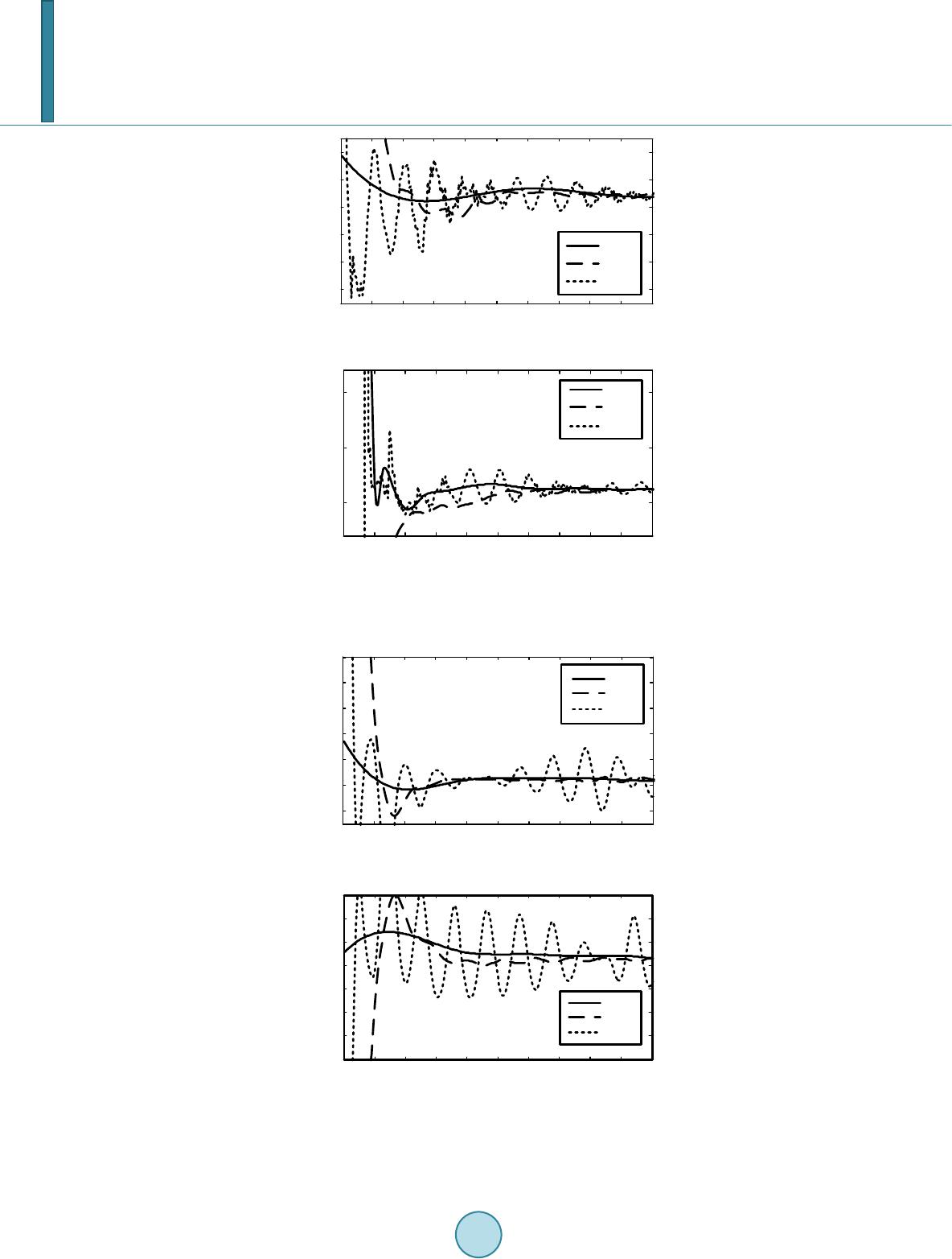 X. M. Liu, Z. Y. He (a) (b) Figure 2. Resistance and reactance of single phase to ground fault on phase-a at 72% of line length. (a) (b) Figure 3. Resistance and reactance of double phase fault be- tween phase-a and phase-b at 72% of line length. 024681012 14 16 18 20 -30 -20 -10 0 10 20 t/ms Resistance/Ω HHT LS DEA 0246810 12 14 16 1820 50 100 150 t/ms Reactance/Ω HHT LS DEA 0246810 12 14 16 1820 -20 0 20 40 60 80 100 t/ms Resistance/Ω HHT LS DEA 024 6 810 12 14 16 18 20 20 30 40 50 60 70 80 90 t/ms Reactance/Ω HHT LS DEA 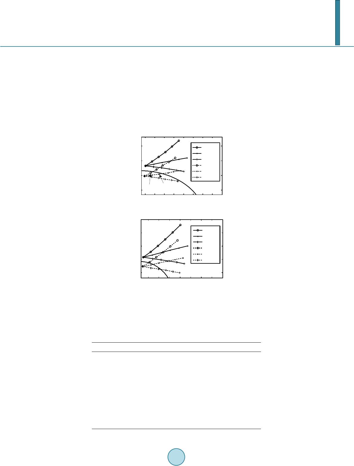 X. M. Liu, Z. Y. He The operation time of HHT based algorithm has been simulated for single phase to ground fault and double phase fault at the location 10%, 50%, 90% of the protected zone. The operation time consists of impedance cal- culation and tripping decision. The fault resistance was set to zero ohm for all cases. Tables 1 and 2 show the simulation results. The proposed algorithm improves the convergence time of DEA algorithm. To analysis the effect of varying the fault resistance, the proposed algorithm has been simulated for single phase to ground fault and double phase fault considering different fault resistances (0, 3, 6, 9, 12 and 15 Ω). Two cases are presented here. In the first case, the faults occurred at the location 95% of the protected zone. The phase difference between the source generator ES and the source generator ER varied from −30˚ to 30˚. In the second case, the faults occurred at the location 105% of the protected zone. The phase difference between the source generator ES and the source generator ER varied from −45˚ to 45˚. F igure 4 shows the estimated imped- ance for different fault resistances. (a) (b) Figure 4. Affect of fault resistance on the evaluated impedance. (a) Single phase to ground fault on phase-a; (b) Double phase fault between phase-a and phase-b. Table 1. Operation time for single phase to ground on phase-a. Fault distance/% Fault angle/˚ Operation time/ms Distance error/% 10 0 7 2.4 45 7 2.3 90 8 2.5 50 0 7 2.0 45 7 2.1 90 8 2.3 90 0 8 1.8 45 8 1.9 90 8 1.9 510 15 20 25 30 35 40 55 65 75 85 R/Ω X/Ω 1.05,-45° 1.05,0° 1.05,45° 0.95,-45° 0.95,0° 0.95,45° 0Ω 3Ω 0Ω 15Ω 6Ω15Ω 10 2030 40 50 60 70 60 70 80 90 100 R/Ω X/Ω 1.05,-30° 1.05,0° 1.05,30° 0.95,-30° 0.95,0° 0.95,30° 0Ω6Ω 15Ω 0Ω 15Ω  X. M. Liu, Z. Y. He Table 2. Operation time for double phase fault between phase-a and phase-b . Fault distance/% Fault angle/° Operation time/ms Distance error/% 10 0 6 2.5 45 6 2.4 90 7 2.4 50 0 7 2.2 45 8 2.3 90 8 2.3 90 0 8 1.7 45 8 1.8 90 8 1.9 6. Conclusion The paper has suggested the HHT based scheme to improve the performance of EDA. The scheme employs Hilbert-Huang transform (HHT) to extract high-frequency components of the results of DEA. Through empirical mode decomposition (EMD), the intrinsic mode functions (IMF) of high frequency harmonics are separated out, and the residue which has monotonic trend is used to evaluate the impedance of faulted line. The proposed scheme improves the convergence time of DEA and accuracy in impedance estimating. Simulation results show that the operation time is around 6 - 8 ms. References [1] P athiran a, V. and M cLaren, P.G. (2 00 5) A Hybrid Algorithm for High Speed Transmission Line Protection. IEEE Transactions on Power Delivery, 20, 2422-242 8. http://dx.doi.org/10.1109/TPWRD.2005.852365 [2] Xu, Z.Y., Huang, S.F. and R an, L. (2008) A Distance Protection Relay for a 1000-kV UHV Transmission Line. IEEE Transactions on Power Delivery, 23, 1795-1804. http://dx.doi.org/10.1109/TPWRD.2008.919038 [3] V azquez, E., Castruita, J., Chacon, O.L. and Conde, A. (20 07) A New Approach Travelling-Wave Distance Protection- Part Ι: Algorithm. IEEE Transactions on Power Delivery, 22, 7 95 -800. [4] Garc ía-Gracia, M., El Halabi, N., Borroy, S. and Giménez de Urtasun, L. (2011 ) Phase Jump Correction Factor Ap- plied to the Differential Equation Algorithm by an Adaptive Scheme. IET Generation, Transactions & Distribution, 5, 266-275. http://dx.doi.org/10.1049/iet-gtd.2010.0247 [5] Mo rais, A.P., Cardoso Jr., G. , Mariotto, L. and Ferreira, G.D. (2011) Numerical Distance Relaying Algorithm Based on Mathematical Morphology and Least-Squares Curve Fitting Method. Electric Power Systems Research, 81, 1144- 1150. http://dx.doi.org/10.1016/j.epsr.2011.01.003 [6] Zhang, Y.X. and Li, K.K. (2000) Study of Adaptive Window Length Algorithm Based on Linear Differential Equation. Proceedings of the CSEE, 20, 24-27. [7] Song, G.B., Liu, L.L., Suonan, J., Yuan, X.H. and Du, B. (20 09 ) Long Transmission Line Protection Based on Para- meter Identification in Time Domain. Automation of Electric Power Systems, 33, 67-70. [8] Ch en, Z.H., Huang, S.F. and Tao, H. L. (2005) Research on the Application of the Bergeron Model to the Differential Equation Algorithm. Automation of Electric Power Systems, 29, 31-34. http://dx.doi.org/10.1016/j.ijepes.2004.07.008 [9] Cho, K.R., Kang, Y.C., Kim, S.S., Park, J.K., Kang, S.H. and Ki m, K.H. (1999 ) An ANN Based Approach to Improve the Speed of a Differential Equation Based Distance Relaying Algorithm. IEEE Transactions on Power Delivery, 14, 349-356. http://dx.doi.org/10.1109/61.754073 [10] Santos, R.C. and Seng e r , E.C. (2011) Transmission Line Distance Protection Using Artificial Neural Networks. Elec- trical Power and Energy Systems, 33, 721-730 . http://dx.doi.org/10.1016/j.ijepes.2010.12.029 [11] Segu i, T., Bertrand, P., Guillot, M., Hanchin, P. and Bastard, P. (2000) Fundamental Basis for Distance Relaying with Parametrical Estimation. IEEE Transactions on Power Delivery, 15, 659-664. http://dx.doi.org/10.1109/61.853001 [12] Garc ía-Gr ac i a , M., El Halabi, N., Montaňés, A., Khodr, H.M. and Villén, M. (2010 ) Improvement of DEA Perfor- mance against Harmonic Distortion. Electric Power Systems Research, 80 , 582-591.  X. M. Liu, Z. Y. He http://dx.doi.org/10.1016/j.epsr.2009.10.012 [13] Qin, S.R. and Zhong, Y. M. (2006) A New Envelope Algorithm of Hilbert-Huang Transform. Mechanical Systems and Signal Processing, 20, 1941-1952. http://dx.doi.org/10.1016/j.ymssp.2005.07.002 [14] Cheng, J.S., Yu, D.J. and Yang, Y. (2007) Application of Support Vector Regression Machines to the Processing of End Effects of Hilbert-Huang Transform. Mechanical Systems and Signal Processing 21, 1197-1211 . http://dx.doi.org/10.1016/j.ymssp.2005.09.005 [15] Akke, M. and Thorp, J.T. (1998) Some Improvements in the Three-Phase Differential Equation Algorithm for Fast Transmission Line Protection. IEEE Transactions on Power Delivery, 13, 66-72. http://dx.doi.org/10.1109/61.660852
|