 Journal of Power and Energy Engineering, 2014, 2, 600-611 Published Online April 2014 in SciRes. http://www.scirp.org/journal/jpee http://dx.doi.org/10.4236/jpee.2014.24081 How to cite this paper: Abu Bakar, A.H., et al. (2014) Comparative Study on Substation Shielding Due to Direct Lightning Strokes. Journal of Power and Energy Engineering, 2, 600-611. http://dx.doi.org/10.4236/jpee.2014.24081 Comparative Study on Substation Shielding Due to Direct Lightning Strokes Ab Halim Abu Bakar1*, Chia Kwang Tan1, Alyaa Zainal Abidin2, Pang Jack Khai2, Hazlie Mokhlis2, Hazlee Azil Illias2 1University of Malaya Power Energy Dedicated Advanced Centre (UMPEDAC), Level 4, Wisma R & D, University of Malaya, Jalan Pantai Baharu, Kuala Lumpur, Malaysia 2Department of Electrical Engineering, Faculty of Engineering, University of Malaya, Kuala Lumpur, Malaysia Email: *a.halim@um.edu.my Received Dec emb er 2013 Abstract Malaysia is one of the many countries that experience high lightning related activities. In fact, ac- cording to Malaysian Meteorological Department the Ground Flash Density (GFD) in Malaysia, it is rated at the fifth place in the ten most lightning cities of the world, with a high keraunic level, which is 240 thunderstorm days per year, and in other words, a Ground Flash Density (GFD) of 48.3 flashes per square kilometer per year. In the power systems, high keraunic level would con- tribute to high possibility of power interruptions such as disruption, degradation, damage and downtime. These outages would ultimately lead to revenue losses and reduction of network relia- bility. These lightning related interruptions may be in terms of direct lightning strikes to the lines or to the equipments in the substation. By the use of Mat Lab GUI (Graphic Users Interface), this study presents a simple computer program which uses the electro-geometric model (EGM) for the designing of substation shielding systems. The EGM uses the concept where the protection zone of a lightning system lies within the radius where the upward channel initiates and propagates through the air terminal to meet the downward leader. This interception point is called “the point of discrimination” and is where the downward leader decides its final jump. The distance at which the last jump occurs is known as the striking distance. With the use of the striking distance and the mathematical equations developed by Young, Brown-Whitehead, IEEE-1992 (IEEE T&D Committee Equations) and IEEE-1995 (IEEE Substations Committee Equations). This project aimed to investi- gate, understand and analyse the substation protection by means of masts and shield wires. The analysis is extended to account for lightning protection provided by single mast to two masts as well as from single shield wire to double shielding wires. The outcomes of these four equations will be compared. Keywords Lightning; El ectro-Geomet ric Model; Striking Distance; Substation Protection; Lightning Protection; M ATLAB *  A. H. Abu Bakar et al. 1. Introduction Malaysia, as a tropical climate country, is situated in one of the highest keraunic region where 180 to 260 thun- derstorm days are recorded per year. It was also recorded that the flash density in Malaysia is within the region of 40 - 50 flashes per square kilometer per year and certain areas up to 50 - 70 flashes per square kilometer per year. High flash density would contribute to high possibility of power interruptions and the effects will be de- pendent upon the extent of the stroke and the sensitivity of the equipment. The effect of the stroke can be graded from minor to severe stages such as disruption of the equipment, which will cause data losses, data and software corruption and false tripping. Degradation of the electronic equipment will shorten its lifetime and increase the percentage of failures. High magnitude of lightning strokes can cause damages to the equipment and facilities and hence, leads to downtime which causes losses of production and business opportunity. As substation and transmission lines were installed, the protection issues of the facilities arises for if there were no shielding against high magnitude of lightning stroke, possible insulation flashover, damage and failure to major substation equipments and substation outage may happen. Since lightning stroke cannot be prevented, researchers studied its characteristics and developed a number of mathematical models for protection against lightning strokes. These models can be categorised into two classes which are Empirical Model and Electro- Geometric Model (EGM). The Empirical Model is based on the concept that “the shielding device (Shielding wires or masts) can intercept all lightning strokes to the protection device if it maintains a certain geometrical relationship (seperation and differential height) to the protected object. Meanwhile, for the EGM, the ‘Protection zone of a lightning protection system may be defined as the volume of space inside which an air termination provides protection against a direct lightning strike by attracting the strike to itself”. This study focuses on comparing and analyzing the outcomes of the four models of EGM with respect to dif- ferent critical current, protective equipment heights and area. A software program was developed to determine the minimum height of the shielding wires and shielding masts for the purpose of substation lightning protec- tion. 2. Electro-Geometric Model: Striking Distance Equations The EGM uses the concept where the potection zone of a lightning system lies within the radius where the upward channel initiates and propagates through the air terminal to meet the downward leader [1] [2]. The interception point is called “the point of discrimination” and is where the downward leader dicides its final jump. The distance at which the act of last jump happens is called the striking distance. In short, the striking distance is the distance between the stepped leader and the object that the leader decides to strike. The EGM models that are used in this study are of Young, Brown-White head, IEEE-1992 and IEEE-1995. Their concepts are the same, which use the striking distance as a basic but with its own individual mathematical equations. The theory was based on Lee’s Rolling Sphere concept and Andrew R Hileman, “Insulation Coordination for Power Sys- tems, Chapter 8, Shielding of Substations.” [3]. When the “air breakdown” point is exceeded, stepped leader starts to propagate slowly towards the ground and it will decide where it wants to strike as it is closer to the earth’s surface. The final jump occurs at “the point of discrimination where the object that the leader wants to strike initiates a return stroke [4]. The distance at which the last jump occurs, which is also called “the point of discrimination” is known as the “striking distance” [5]. The illustration of striking distance is shown in Figure 1. Unlike a transmission protection, the height and size of the protection object changes and so will be the height of the shielding wires and masts. Hence, three striking distances are taken into concern for the design: a) The striking distance to the shielding wire or mast, . b) The striking distance to the object to be protected, . c) The striking distance to ground, . The relationships between the three are: (1) (2) where and refer to the coefficients of the striking distance to shield wire or mast and the striking dis- tance to protected object respectively. 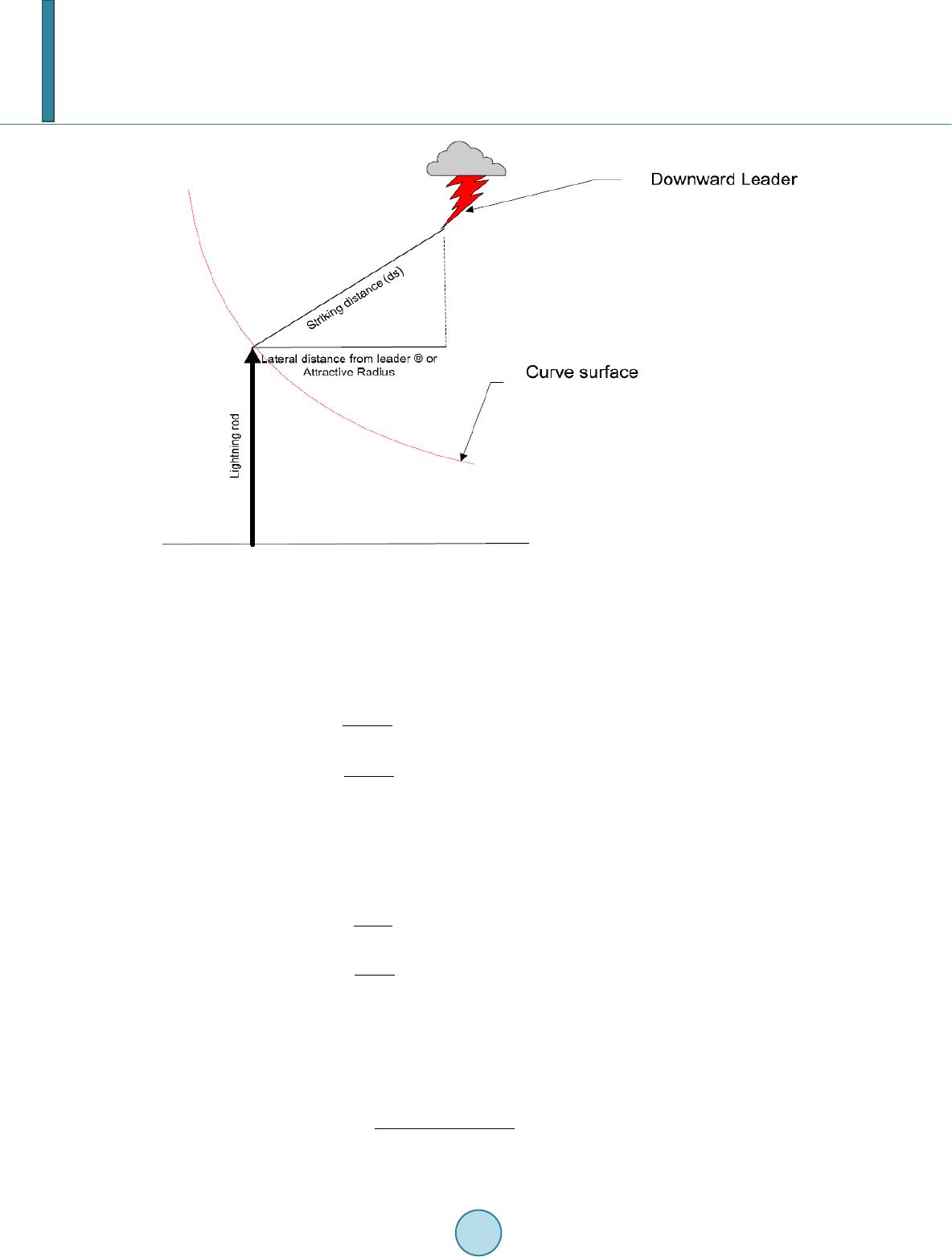 A. H. Abu Bakar et al. Figure 1. Striking distance. 2.1. Young’s Equations The equations used by Young’s for calculating the striking distance to ground, , and the coefficients and are : (3) for h ≥ 18 m otherwise (4) for y ≥ 18 m otherwise (5) 2.2. Brown-White Head—CIGRE Equations The formulas that Brown-White head and CIGRE adopt are: (6) for h ≥ 18 m otherwise (7) for y ≥ 18 m otherwise (8) 2.3. IEEE-1992—IEEE T&D Committee Equations The mathematical model proposed by IEEE-1992–IEEE T&D Committee is: (9) (10)  A. H. Abu Bakar et al. For h ≥ 30, set h = 30 (11) For y ≥ 30, set y = 30 2.4. IEEE-1995—IEEE Substations Committee Equations The mathematical equations generated by the IEEE-1995—IEEE Substations Committee are: (12) (13) where, k = 1 for strokes to wires k = 1.2 for strokes to mast s All the magnitude of I are in kA while , , , , , h and y are in meters. 3. Software Development: Substation Shielding MATL AB ® (MATrix LABoratory) is chosen as the computer programming software to be used for the simula- tion of the substation shielding. In order for comparative studies, a general criterion is set. The models will be simulated under two different Design Current (Ic): 3 kA and 5 kA, which would be the design currents for the nominal voltage used in our transmission systems that is: 132 kV and 275 kV. Besides that, the protected area or object would be set to have a length and width of 6 m × 6 m. As for the object’s height, it would vary from 3 m to 18 m and that the distance between the masts or wires and the protected object should be equal or greater than 2 m. Table 1 shows the pa- rameter for the type of shielding used in the simulation [3]. The formulas and equations used in this program are: Table 1. Types of shielding. Types of Shielding Protection Zone Single Wire Double Wires ()( ) 2 2 22 s gcg arrhr ry=− −−−− One Mast ( ) 2 22 2 0g cg axSr ry=++ −− Two Masts h = minimum protection height required to protect the equipment; = striking distance to ground; = striking distance to the shielding wire of mast; = striking distance to the object to be protected; = mid-width of equipment; Y = height of equipment; RC = dis- tance to center between two shield wires/masts; a = protective zone radius; Sg = separation distance between the mast and the equipment’s end point; RPO = outward protective zone.  A. H. Abu Bakar et al. I. Young’s Equations II. Bro wn -W hite head —CIGRE Equations III. IEEE-1992—IEEE T&D Committee Equations IV. IEEE-1995—IEEE Substations Committee Equations 4. Results and Discussions The simulations are aimed at comparing the outcomes of each model with respect to different critical design current and protected objects due to direct lightning strokes. It also provides the comparative shielding heights of masts and wires of different models used. For the first part, the results for the design current Ic = 3 kA would be discussed for the four models (Young’s, CIGRE, IEEE-92 and 95) used in the designs of single and two masts as well as single and double wires shielding. In the second part, the outcomes for the design current Ic = 5 kA would be discussed. 4.1. Simulation Results for Single Mast Shielding with Design Current 3 kA & 5 kA The values used in the single mast shielding for a design current of 3 kA and 5 kA is shown in Table 2. The striking distance to ground, rg, was calculated for the four models: Young’s = 38.37 m, CIGRE = 14.59 m, IEEE-92 = 18.36 m and IEEE-95 = 19.61 m respectively for Ic = 3 kA. For Ic = 5 kA, the striking distance to ground, rg are: Young’s = 31.71 m, CIGRE = 21.40, IEEE-92 = 25.62 m and IEEE-95 = 27.33 m respectively. The striking distance to ground, rg, was very important because it represents the maximum effective height or limits of the shielding masts or wires for effective protection on the substation’s equipment and thus, it was the limitation of each model for providing useful masts and wires height for shielding against lightning strokes. Furthermore, it also influences the radius of the protective zone (striking distance to protected object, rc). Espe- cially when using single and double masts as well as single wire shielding for the three types of shielding were influenced by ground or rg. Thus, those objects that needed a protection height that exceed the value of rg would be exposed to potential lightning strokes. As for the simulation results, the equations used in the four models will set the limitation at rg and hence, those protective heights that were equal to rg will be considered as ineffective shielding for the respective pro- tected equipment. By comparing the rg of Ic = 5 kA and the rg of Ic = 3 kA, the Ic = 5 kA has a larger rg. This is due to its higher design current (Ic) and from the formula given. The rg of all four models were directly related to the values of Ic and hence, higher the value of Ic, the higher rg is. From Table 3, when Ic = 3 kA, the results show that Young’s model could successfully protect the equipment from height varies from 3 m to 16 m while the other models were inapplicable for protection. This was because Young’s model has the biggest value in rg and hence, could provide a much higher effective mast height for the object and also a larger radius of protective zone (striking distance to object, rc) for the protected equipment since . Meanwhile, for Ic = 5 kA, Young’s model shows effective shielding for all heights from y = 3 m to 18 m for the protected object, while CIGRE model could only provide effective protection for object’s height of y = 3 m and 4m. Both IEEE-92 and 95 could provide protection for object’s height from y = 3 m up to 7 m. By comparing the results between Ic = 3 kA and Ic = 5 kA, one could notice that when Ic = 5 kA, a s horte r masts is required in protecting an object of the same size. This was due to its larger rg values that will increase the ra- dius of the striking distance to mast, rs, and intentionally increases the radius of the striking distance to object, rc, which will finally increase the area of the protective zone. Thus, a shorter mast height is required for the protec- tion of the object with the same size. Table 2. Simulation parameters for single mast shielding with Ic = 3 kA, 5 kA. Description Value Type of Shielding Method Apply Single Mast Shielding Design Current for Substation (I) 3 kA & 5 kA Mid -Width of Protected Equipment (x) 3 m Starting Iteration Height (h) 18 m Protected Equipment Height (y) 3 m - 18 m  A. H. Abu Bakar et al. Table 3. Simulation results for variation of protected equipment height for single mast shiel- ding with Ic = 3 kA, 5 kA. Height, h (m) Ic = 3 kA Height, h (m) Ic = 5 kA y (m) Yo ung ’s GIGRE IEEE-92 I E EE -95 Young ’s GIGRE IEEE -92 IE EE -95 3 7.97 14. 59 13. 51 1 4. 64 7.37 12.52 9.39 9.83 4 9.79 14. 59 18. 38 1 9. 61 9.05 17.29 11.52 1 2. 23 5 11.59 1 4. 59 1 8.38 1 9. 61 1 0.71 2 1. 40 1 3.68 1 4. 83 6 13.41 1 4. 59 1 8.38 1 9. 61 1 2.35 2 1. 40 1 5.90 1 7. 85 7 15.27 1 4. 59 1 8.38 1 9. 61 1 4.00 2 1. 40 1 8.23 2 2. 03 8 17.19 1 4. 59 1 8.38 1 9. 61 1 5.67 2 1. 40 1 5.11 2 7. 33 9 19.02 1 4. 59 1 8.38 1 9. 61 1 7.36 2 1. 40 1 8.44 2 7. 33 10 20.79 14. 59 18. 38 1 9. 61 1 8.93 2 1. 40 2 5.62 2 7. 33 11 22.63 14. 59 18. 38 1 9. 61 2 0.42 2 1. 40 2 5.62 2 7. 33 12 24.56 14. 59 18. 38 1 9. 61 2 1.93 2 1. 40 2 5.62 2 7. 33 13 26.63 14. 59 18. 38 1 9. 61 2 3.46 2 1. 40 2 5.62 2 7. 33 14 28.90 14. 59 18. 38 1 9. 61 2 5.01 2 1. 40 2 5.62 2 7. 33 15 31.51 14. 59 18. 38 1 9. 61 2 6.61 2 1. 40 2 5.62 2 7. 33 16 32.06 14. 59 18. 38 1 9. 61 2 8.25 2 1. 40 2 5.62 2 7. 33 17 38.37 14. 59 18. 38 1 9. 61 2 9.94 2 1. 40 2 5.62 2 7. 33 18 38.37 14. 59 18. 38 1 9. 61 3 1.71 2 1. 40 2 5.62 2 7. 33 In the column of IEEE-92, it shows a steady increase in mast height in accordance to the increase of object height. But, it suffered a sudden dip at y = 8 m and gradually climb back up at y = 9 m and finally reaches its saturation state at y = 10 m (the cells which were painted in green represent the object’s height that the models fail in providing effective shielding). The cause of the dip was due to the iteration process which it could not converge into a final value but instead tend to oscillate from h = rg and h = 15.11 m and finally, ended up at h = 15.11 m when the iteration process finished. As a result, the required shielding height was undetermined and thus, the model could not provide the effective protection for the specified object height. The oscillation of the mast height also occurs at y = 9 m before it goes to saturation at y = 10 m. As a conclusion, all masts height re- sults for IEEE-92 starting from y = 8 m to y = 18 m could not supply effective protection to the object. 4.2. Simulation Results for Two Masts Shielding with Design Current of 3 kA & 5 kA The values used in the two masts shielding for a design current of 3 kA and 5 kA was shown at Table 4. Table 5 shows the simulation results for two masts shielding with design current of 3 kA and 5 kA. In this case, the striking distance to ground, rg, still plays an important role because double masts shielding was still influenced by ground. The rg results for all four models were the same as those of one mast shielding. But, since the protected object was situated between the two masts, the influence of rg would be on the sides of the object (side strokes of lightning) but not on top of the object (direct lightning strokes). The protective zone of the two masts shielding was larger compared to the single mast shielding and hence, the required shielding mast’s height for protecting the same object would be shorter. So, from Table 5, it was shown that there where improvement from the four models where the required masts height were reduced compared to the results when one mast was used and that Young’s model could successfully protect object for height from y = 3 m to 18 m and that CIGRE model could provide protection for y = 3 m and 4 m while IEEE-92 and 95 could offer effective protection for object’s height from 3 m to 8 m when the Ic = 3 kA was used. When Ic = 5 kA used, the results also improved in the usage of  A. H. Abu Bakar et al. Table 4. Simulation parameters for two masts shielding with Ic = 3 kA, 5 kA. Description Val ue Type of Shielding Method Apply Two Mast Shielding Design Current for Substation (I) 3 kA & 5 kA Mid -Width of Protected Equipment (x) 3 m Starting Iteration Height (h) 18 m Protected Equipment Height (y) 3 m - 18 m Table 5. Simulation results for variation of protected equipment height for two masts shiel- ding with Ic = 3 kA, 5 kA. Height, h (m) Ic = 3 kA Height, h (m) Ic = 5 kA y (m) Yo ung ’s GIGRE IEEE-92 I E EE -95 Young ’s GIGRE IEEE -92 IE EE -95 3 4.79 7.72 6.15 6.22 4.58 5.94 5.25 5.35 4 6.04 10. 36 7.73 7.84 5.81 7.47 6.58 6.72 5 7.29 14. 59 9.36 9.56 5.81 7.47 6.58 6.72 6 8.53 14. 59 11. 10 1 1. 46 8.22 10.72 9.24 9.49 7 9.78 14. 59 13. 02 1 3. 71 9.42 12.55 10.57 1 0. 91 8 11.03 1 4. 59 1 5.27 1 7. 18 1 0.62 1 4. 66 1 1.92 1 2. 37 9 12.28 1 4. 59 1 8.38 1 9. 61 1 1.82 1 7. 51 1 3.29 1 3. 90 10 13.55 14. 59 18. 38 1 9. 61 1 3.03 1 7. 33 1 4.67 1 5. 52 11 14.84 14. 59 18. 38 1 9. 61 1 4.24 2 1. 40 1 6.08 1 7. 27 12 16.14 14. 59 18. 38 1 9. 61 1 5.47 2 1. 40 1 7.52 1 9. 25 13 17.47 14. 59 18. 38 1 9. 61 1 6.70 2 1. 40 1 8.97 2 1. 70 14 18.70 14. 59 18. 38 1 9. 61 1 7.94 2 1. 40 1 4.89 2 6. 63 15 19.87 14. 59 18. 38 1 9. 61 1 9.02 2 1. 40 1 6.72 2 7. 33 16 21.05 14. 59 18. 38 1 9. 61 2 0.08 2 1. 40 1 8.90 2 7. 33 17 22.24 14. 59 18. 38 1 9. 61 2 1.15 2 1. 40 2 2.06 2 7. 33 18 23.45 14. 59 18. 38 1 9. 61 2 2.21 2 1. 40 2 5.62 2 7. 33 CIGRE, IEEE-92 and 95 models, where CIGRE provides protection from y = 3 m to 9 m, IEEE-92 supplies protection from y = 3 m to 13 m and IEEE-95 could give protection up to y = 14 m. It can be seen from the re- sults of Ic = 5 kA, the IEEE-92 suffered from a sudden dip at y = 14 m and thus, it ineffective shielding starts at that object’s height. 4.3. Simulation Results for Single Wire Shielding with Design Current of 3 kA & 5 kA The values used in the single wire shielding for a design current of 3 kA and 5 kA is shown in Table 6. The use of wire shielding was a method where wires were stretched on top of the protected object for the purpose of lightning strokes protection. It could be assumed that the shielding wire is equal to a couple of masts lining on a straight line to provide lightning protection and thus it offers a much larger protective area. In conclusion, wires shielding should provide better shielding compare to masts shielding. The single wire shielding was a two masts shielding with an additional shield wire attached to its masts which is situated directly above the protected object. From Table 7, for Ic = 3 kA, it shows that the Young’s model were capable of giving effective shielding to all  A. H. Abu Bakar et al. Table 6. Simulation parameters for single wire shielding with Ic = 3 kA & 5kA. Description Value Type of Shielding Method Apply Single Wire Shielding Design Current for Substation (I) 3 kA & 5 kA Mid -Width of Protected Equipment (x) 3 m Starting Iteration Height (h) 18 m Protected Equipment Height (y) 3 m - 18 m Table 7. Simulation results for variation of protected equipment height for single wire shiel- ding with Ic = 3 kA, 5 kA. Height, h (m) Ic = 3 kA Height, h (m) Ic = 5 kA y (m) Young’s GIGRE IEEE-92 IEEE-95 Young’s GIGRE IEEE-92 IEEE-95 3 4.42 6.10 5.28 5.74 4.28 5.15 4.72 5.05 4 5.66 8.04 6.76 7.45 5.49 6.60 6.03 6.46 5 6.89 10.47 8.27 9.34 6.69 8.08 7.33 7.89 6 8.12 14.59 9.85 11.65 7.88 9.61 8.62 9.36 7 9.34 14.59 11.52 16.34 9.07 11.23 9.92 10.89 8 10.57 14.59 13.37 16.34 1 0. 26 13. 01 11.23 1 2. 51 9 11.81 14.59 18.38 16.34 1 1. 45 15. 07 12.56 1 4. 29 10 13.05 14.59 18. 38 16.34 1 2. 64 1 7.89 13.90 1 6. 37 11 14.31 14.59 18. 38 16.34 1 3. 84 1 7.37 15.26 1 9. 22 12 15.58 14.59 18. 38 16.34 1 5. 05 2 1.40 16.64 2 2. 77 13 16.88 14.59 18. 38 16.34 1 6. 26 2 1.40 18.05 2 2. 77 14 18.17 14.59 18. 38 16.34 1 7. 48 2 1.40 13.78 2 2. 77 15 19.31 14.59 18. 38 16.34 1 8. 61 2 1.40 15.41 2 2. 77 16 20.46 14.59 18. 38 16.34 1 9. 67 2 1.40 17.24 2 2. 77 17 21.62 14.59 18. 38 16.34 2 0. 72 2 1.40 19.48 2 2. 77 18 22.78 14.59 18. 38 16.34 2 1. 77 2 1.40 23.02 2 2. 77 varied object’s height from y = 3 m to 18 m, CIGRE model provides protection for object’s height from y = 3 m to 5 m, IEEE-95 supplied protection from y = 3 m to 8 m and lastly, IEEE-95 could protect object’s height from y = 3 m to 6 m. Whereas, for Ic = 5 kA, the CIGRE model could provide protection for object’s height of y = 3 m to 11 m, IEEE-92 for y = 3 m to 13 m and last but not least, IEEE-95 for y = 3 m to 11 m. It was noticed that the wire height required for protection was much lesser than the two masts shielding. Thus, confirming that the wire shielding method provides better shielding and larger protective area. The rg of IEEE-95 was 16.34 m while the others rg remain the same as shielding masts. This will make the striking distance to object, rc, to become smaller. Although IEEE-95 shielding wire required lesser height com- pare to masts, it could only provide efficient protection up to y = 6 m only for Ic = 3 kA. For Ic =5 kA, it could only give effective shielding for y = 3 m to 11 m instead of until 14 m which was the ability of the two masts shielding. This is because of the rg is multiplied by a coefficient of 1 and this intentionally decreases its striking distance and hence, decreases its area of protection. But nonetheless, for the object’s height that it could give protection to, the required shielding height was reduced. 4.4. Simulation Results for Double Wires Shielding with Design Current of 3 kA & 5 kA The values used in the double wires shielding for a design current of 3 kA and 5 kA is shown in Table 8. The concept of the two wires shielding is the same as the single wire shielding but it provides a much larger shiel- ding area and thus requires less shielding height compared to the single wire shielding method. Table 9 shows the simulation results for double wires shielding with a design current of 3 kA and 5 kA The  A. H. Abu Bakar et al. Table 8. Simulation parameters for two wires shielding with Ic = 3 kA, 5 kA. Description Value Type of Shielding Method Apply Two Wires Shielding Design Current for Substation (I) 3 kA & 5 kA Mid -Width of Protected Equipment (x) 3 m Starting Iteration Height (h) 18 m Protected Equipment Height (y) 3 m - 18 m Table 9. (a) Simulation results for variation of protected equipment height for two wires shielding with Ic = 3 kA, 5 kA using Young’s Equations; (b) Simulation results for variation of protected equip- ment height for two wires shielding with Ic = 3 kA, 5 kA using CIGRE Equations; (c) Simulation re- sults for variation of protected equipment height for two wires shielding with Ic = 3 kA, 5 kA using IEEE-92 Equations; (d) Simulation results for variation of protected equipment height for two wires shielding with Ic = 3 kA, 5 kA using IEEE-95 Equations. (a) Young’s Ic = 3 kA Yo ung’s Ic = 5 kA y (m) h (m) a (m) h (m) a (m) 3 3.33 0.76 3.28 0.71 4 4.33 0.64 4.28 0.60 5 5.33 0.57 5.28 0.53 6 6.33 0.51 6.28 0.48 7 7.33 0.46 7.28 0.43 8 8.33 0.42 8.28 0.40 9 9.33 0.38 9.28 0.37 10 10.33 0.35 10.28 0.34 11 11.33 0.33 11.28 0.32 12 12.33 0.31 12.28 0.30 13 13.33 0.29 13.28 0.28 14 14.33 0.27 14.28 0.26 15 15.33 0.25 15.28 0.25 16 16.33 0.23 16.28 0.23 17 17.33 0.22 17.28 0.22 18 18.30 0.22 18.28 0.22  A. H. Abu Bakar et al. (b) CIGRE Ic = 3 kA CIGRE Ic = 5 kA y (m) h (m) a (m) h (m) a (m) 3 3.88 1.05 3.59 0.94 4 4.88 0.86 4.59 0.79 5 5.88 0.71 5.59 0.68 6 6.88 0.60 6.59 0.59 7 7.88 0.50 7.59 0.52 8 8.88 0.41 8.59 0.46 9 9.88 0.33 9.59 0.41 10 10.88 0.26 10.59 0.36 11 11.88 0.20 11.59 0.32 12 12.88 0.13 12.59 0.28 13 13.88 0.07 13.59 0.24 14 14.88 0.01 14.59 0.21 15 15.88 −0.05 15.59 0.18 16 16.88 −0.11 16.59 0.15 17 17.88 −0.18 17.59 0.12 18 18.77 −0.10 18.49 0.17 (c) IEEE -92 Ic = 3 kA IEEE-92 Ic = 5 kA y (m) h (m) a (m) h (m) a (m) 3 3.63 0.95 3.44 0.84 4 4.63 0.79 4.43 0.71 5 5.62 0.68 5.43 0.61 6 6.62 0.58 6.42 0.54 7 7.61 0.51 7.42 0.48 8 8.61 0.45 8.42 0.44 9 9.60 0.39 9.41 0.40 10 10.60 0.34 10.41 0.36 11 11.59 0.30 11.40 0.33 12 12.58 0.26 12.40 0.30 13 13.58 0.23 13.39 0.28 14 14.57 0.19 14.39 0.25 15 15.56 0.16 15.38 0.23 16 16.56 0.14 16.38 0.21 17 17.55 0.11 17.37 0.20 18 18.54 0.09 18.37 0.18  A. H. Abu Bakar et al. (d) IEEE -95 Ic = 3 kA IEEE-95 Ic = 5 kA y (m) h (m) a (m) h (m) a (m) 3 3.78 1.02 3.56 0.92 4 4.78 0.84 4.56 0.77 5 5.78 0.71 5.56 0.67 6 6.78 0.60 6.56 0.58 7 7.78 0.51 7.56 0.52 8 8.78 0.44 8.56 0.46 9 9.78 0.37 9.56 0.41 10 10.78 0.31 10.56 0.36 11 11.78 0.25 11.56 0.32 12 12.78 0.20 12.56 0.29 13 13.78 0.14 13.56 0.25 14 14.78 0.09 14.56 0.22 15 15.78 0.05 15.56 0.19 16 16.78 0 16.56 0.17 17 17.78 −0.05 17.56 0.14 18 18.78 −0.10 18.56 0.11 striking distance to ground, rg, is the same as single wire shielding and from Table 9, it is noticeable that there is a column for “a”, which is the outer protective zone of the shielding wires. From Table 9 also, it shows that all four models satisfy the criterion of protection and thus could provide effective shielding to the object against lightning strikes at object’s height from y = 3 m to 18 m with the lowest shielding height needed. Note that the outer protective zone, a ≥ −2 m, where the 2 m is the minimum separation between the shield wires and the pro- tected object. Finally, by comparing the outcomes of the two methods (masts and wires shielding), it was ob- vious that wires shielding provides better protection and larger shielding area than the masts shielding and with a lesser shielding height; and also it was plain in sight that the more masts or wires are used the better protection it gives against potential strokes but this leads to higher costs. 5. Conclusion The paper presents a comparative study of the various substation shielding methods together with various ma- thematical models. It was found that the use of more masts and shield wires is superior to lesser masts and shield wires. Besides, the wires shielding is superior against masts shielding. It was also shown that Ic = 5 kA is ad- vantageous because the protected object will require a shorter shielding masts or wires height as compared to Ic = 3 kA. Finally, it was shown that the Young’s Equation is the most superior model due to its capability in of- fering lightning protection to large majority of the protected equipment height. References [1] Eriksson, A.J. (1987) An Improved Electrogeometric Model for Transmission Line Shielding Analysis. IEEE Transac- tions on Power Delivery, 2, 871 -886. http://dx.doi.org/10.1109/TPWRD.1987.4308192 [2] Mousa, A.M. and Srivastava, K.D. (1989 ) The Implications of the Electrogeometric Model Regarding Effect of Height of Structure on the Median Amplitude of Collected Lightning Strokes. IEEE Transactions on Power Delivery, 4, 1450- 1460. [3] Hileman, A.R. (1999) Insulation Coordination for Power Systems. CRC Press, Taylor & Francis Group.  A. H. Abu Bakar et al. [4] Chowdhuri, P. and Kotapalli A.K. (1989 ) Significant Parameters in Estimating the Striking Distance of Lightning Strokes to Overhead Lines. IEEE Transactions on Power Delivery, 4, 1970-1981. http://dx.doi.org/10.1109/61.32697 [5] Cooray, V., Rakov, V. and Theethayi, N. (2007) The Lightning Striking Distance—Revisited. Journal of Electrostatics, 65, 296-306. http://dx.doi.org/10.1016/j.elstat.2006.09.008
|