 Journal of Power and Energy Engineering, 2014, 2, 564-572 Published Online April 2014 in SciRes. http://www.scirp.org/journal/jpee http://dx.doi.org/10.4236/jpee.2014.24076 How to cite this paper: Zhao, X.D., Li, K. and Zheng, M. (2014) Analysis of Transmission Loss in Droop Control of a Multi- Terminal HVDC System. Journal of Power and Energy Engineering, 2, 564-572. http://dx.doi.org/10.4236/jpee.2014.24076 Analysis of Transmission Loss in Droop Control of a Multi-Terminal HVDC System Xiaodong Zhao1, Kang Li1, Min Zheng2 1School of Electronics, Electrical Engineering and Computer Science, Queen’s University, Belfast, UK 2School of Mechatronic Engineering and Automation, Shanghai University, Shanghai, China Email: xzhao06@qub.ac.uk Received January 2014 Abstract High Voltage Direct Current (HVDC) electric power tran smission is a promising technology for in- tegrating offshore wind farms and interconnecting power grids in different regions. In order to maintain the DC voltage, droop control has been widely u sed. Transmission line loss c on sti tute s an import part of the total power loss in a multi-terminal HVDC scheme. In this paper, the relation between droop controller design and transmission loss has been investigated. Different MTDC layout configurations are compared to examine the effect of droop cont roller design on the trans- mission loss. Keywords MTDC ; HVDC ; VSC; Transmission Loss; Droop Control 1. Introduction Renewable energy is predicted to supply 12% of the world’s electricity by 2020 [1]. In order to integrate various renewable energies such as offshore wind farms into the existing AC grid, the concept of multi-terminal HVDC (MTDC) has been proposed. The biggest possible future project is the European Super-grid [2]. A MTDC net- work can connect AC power grids of different voltages, frequencies with decoupled connection and reduce the effect of wind power fluctuation on power transmission and maximize power transmission efficiency. Seamless integration of offshore energy into the existing power grid has brought in the utilization of HVDC transmission, which draws little capacitive current compared with the high voltage AC (HVAC) solution [3]. Voltage source converter (VSC) can work as an interface between DC and AC networks. Compared with tradi- tional line commutated converters (LCC), VSC using high voltage IGBT is capable of switching at a higher op- erating frequency. Advantages of VSC-HVDC include independent control of active and reactive power, fast and reversible con- trol of power flow, and asynchronously decoupling AC grids, etc. The control of VSC in a MTDC has been well studied in the literature. Its operation modes can be generally classified as DC voltage control or active power control, and reactive power or AC voltage control. For the control of DC voltages involving more than one VSC terminal, two categories of control methods exist: master-slave control and DC voltage droop control. In a mas-  X. D. Zhao et al. ter-slave controlled network, one VSC terminal works as a master terminal, maintaining the DC voltage at a fixed level. Other slave terminals can be assigned to deliver power out of the DC network using active power control. Power transmitted in the master terminal is thus influenced by other terminals’ capabilities. Its normal operation will determine the whole system stability, so fast communication between terminals is needed. While using voltage droop control, there is no DC voltage regulating terminals. Each terminal will maintain the DC voltage, delivering active power at the same time [4]-[6]. Power transmitted by each terminal is determined by the DC voltage so influenced by every terminal. The power transmission duties are shared between different terminals with no communication needed, providing a more reliable network. The idea of droop control is based on frequency-power control in the traditional AC power systems. It is more widely used compared with the master-slave method, due to its simplicity and the ease of power sharing be- tween different terminals. However, unlike frequency in a traditional AC system, voltage is not a universal mea- surement of the DC network when using DC voltage droop control. DC voltage error caused by droop control and power loss on the transmission line will add mismatch to the ideal droop control design. This impact on the power dispatch has been analyzed in [5]. Different power dispatch modes using voltage droop control have been compared in [4] [6]. In [7], a methodology to design the required droop gains is proposed to optimize system power transmission. On the other hand, the operation and transmission cost of the MTDC network is part of the overall power loss. In order to minimize the loss, this optimal power flow (OPF) problem of a MTDC network- ing in traditional AC environment can be solved based on traditional optimal algorithms. In [8], the losses of the different components of a VSC HVDC system and the impact of the installation on overall system losses in meshed networks are studied. A sequential AC/DC power flow algorithm is proposed to solve networks con- taining VSC MTDC systems in [9]. Two different VSC control strategies, namely the constant DC voltage con- trol (master-slave control) and DC voltage droop control, are considered in [10] to minimize the transmission loss of the whole AC/DC network. Reference [11] combines the OPF approach with the control of a multi-ter- minal HVDC system. The optimal power flow computes optimal voltages and communicates them to the grid- side VSC in order to ensure minimum losses in the power transmission. However, the relation between the droop control parameters and minimum transmission loss is not clear when OPF is involved in the operation of MTDC using droop control. In this paper, the dependence of transmission loss on droop control design is analyzed, i.e., the condition for achieving a minimum loss operation point. The requirement on DC voltage is derived in order to minimize the transmission loss and the effect of DC voltage drop is considered in achieving the best droop control design. The paper is organized as follows. Section II introduces different control modes for grid side and wind farm side converters. In Section III, the effect of grid side DC voltage on transmission loss is analyzed. Then DC voltage variations caused by droop control are considered to investigate the changes in the power loss. Simulations using Simulink are carried out in Section V. Finally Section VI is the conclusion. 2. Control Modes for Different Converters In a typically configured MTDC system, there exist two kinds of converters: grid side converter (GSVSC) and wind farm side converter (WFVSC). GSVSC and WFVSC have different working modes, determined by the DC voltage and current. The voltage–current characteristics of WFVSC and GSVSC have been introduced and studied in [7] [12] [13]. In this paper, a four terminal MTDC network is studied, as shown in Figure 1. On the left side of MTDC is the WFVSC integrating various wind farms, such as DIFG or full converter based induction generators. The duty for the WFVSC is to deliver all the possible wind power collected by the wind farm to the DC cable, meanwhile maintaining the AC side voltage or providing reactive power support if necessary. The GSVSC will try to control the DC voltage at a desired level, delivering the power out of the DC cable. Proper power transfer is indicated by the DC voltage. If the injected power is higher than delivered, the DC voltage will rise, otherwise it will fall. Thus for a MTDC network in normal operation, the basic tasks are to transfer power while maintaining the DC voltage. 2.1. Wind Farm Side Converter Control The WFVSCs have three operation modes, characterized by Equation (1),  X. D. Zhao et al. Figure 1. Typical four-terminal HVDC network. () /& k kwfLkwfL kk kkwfLkkh khk kh KE EEE IPEE EII I II − ≥ <<= ≥ (1) where Ik is the transmitted DC current from the k-th terminal, Kk is the voltge droop, Ek is the DC voltage, Ewf L is the maximum voltage allowed, Pk is the power injected at the k-th terminal, Ikh is the maximum current al- lowed. In normal operation, the WFVSC delivers all the power collected from wind farm to the DC grid, as a constant power source. If fault occurs in the onshore AC grid, the DC voltage will rise. When the DC voltage is higher than EwfL, the WFVSC will enter droop control mode, just like GSVSC, trying to reduce the DC voltage. Otherwise, if the current exceeds the limitation of converter, the WFVSC will also work in the current limitation mode. 2.2. Grid Side Converter Control Each GSVSC has two operation modes, as shown in Equation (2) 0 () k kkkkh kkhk kh KE EII II II −< =≥ (2) where Ek is the DC voltage, Ek0 is the reference voltage, Ikh is the maximum current limitation for the converter, Kk is the droop control parameter. In normal operation, each GSVSC works like constant voltage source with a pure resistance characterized by the droop parameter Kk, so each terminal can deliver power out of the DC grid while contributing to maintain the DC voltage. Under an AC grid fault, the power delivered will be limited by the maximum current Ikh. 3. Effect of Terminal Voltages on Transmission Loss In a four-terminal HVDC system using droop control, the control scheme for each GSVSC in normal operation can be represented by Figure 2. Using the number order in Figure 1, the relation between DC current and voltage for each GSVSC and WFVSC is, 1 11 2 22 333 0 444 0 / / () () I PE I PE IKE E IKE E = = = − = − (3) The transmission loss is determined by the cable resistance and cable current. (4) where Ii is the cable DC current and Ri is the equivalent cable resistance.  X. D. Zhao et al. Figure 2 . Droop control scheme of a VSC. In an existing MTDC network, the cable resistance is almost unchanged and the current is determined by the power injected from the power source such as wind farms or generators. In order to analyse the effect of droop parameter on the transmission loss, two steps are carried out. First, each wi nd farm is simplified with a constant current i njectio n, thus neglecting the voltage change caused by the droop control, to inspect effect of voltage difference between droop controlled terminals on the power transmission loss. Second, the impact of voltage change caused by droop control is analysed. Three different layout cases are considered for a four terminal HVDC connection, with two WFVSCs and two GSVSCs. In each case, the WFVSC is modelled with co nstant c urr e nt inje ction, thus omitting the DC voltage variations. The requirements for grid side DC voltages are inspected to achieve the minimum transmission loss. 3.1. Case 1: With Wind Farm Interconnection Case 1 is two wind farms interconnected by a common cable, then connected to grid side converters respectively, as shown in Figure 3. If we define the voltage difference between the two grid side converters as , the power loss on the line resistance can be calculated as 22 22222 32 21 12 231 12 23123 123 () loss x RI RIE PIRIR IRIRIRRRR RRR −∆ =++=+− + ++ ++ (5) It can be easily observed that the power consumption can be minimized when , which means the ter- minal side voltage should be equal in order for the maximal efficiency. In this case, the minimal power loss is 2 22 32 21 12 23123 () loss RI RI PIR IRRRR − =+− ++ (6) Another important observation is that, the power loss can be further minimized when R3I2-R2I1=0, this means that the wind farm side power should be assigned inversely to their transmission line resistance. This result can also be verified if we assume the interconnection current between this two transmission lines is Ix, 2 22 1223 1 ()( ) lossxx x PIIR IIRIR=− ++ + (7) In order to get the minimal power loss, the first order of power loss with respect to current Ix can be deduced as, 2 1321 /2( )2()2 loss xxxx PIRIIR IIIR∂∂=− +++ (8) Thus we can get the optimal current for this case with is (9) 3.2. Case 2: With No Wind Farm Interconnection If the two wind farm locations are close enough, then the cable resistance can be omitted. This is also the case when only one wind farm is transmitting power to two GSVSCs, or the two GSVSCs have a joint connection, as discussed in [7]. In both situations, the transmission loss is given a s , 22 2222 32 21 12 2312 2323 23 () loss RI RIE PIR IRIR IRRRRR −∆ =+=+− + ++ (10) It can be seen that the minimal power loss can also be achieved when the terminal voltages are the same, which is consistent with the result in [7]. In order to get the same terminal voltage for the two GSVSCs, it is ob- vious that the DC current should be reversely proportional with the cable resistance, e.g.  X. D. Zhao et al. Figure 3. Case 1: with wind farm interconnection. Figure 4. Case 2: with no wind farm interconnection. (11) which is also true that 333 033 444 042 () () IKE EKR IKE EKR − == = − (12) 3.3. Case 3: With Grid Side Interconnection Two grid side converters are connected near on-shore grid and are represented by Figure 5. In this case, the transmission loss is 222 1 2231 loss x PIRIR IR= ++ (13) We can get (14) Thus it is obvious that (15) So the minimal loss can be achieved when there is no current flow between the two GSVSCs, which means the voltage difference between them is also zero. It can be concluded that in all cases the minimum cost can be achieved when the voltages on the power shar- ing terminals are balanced. However, because the voltage errors caused by droop control are neglected, this will not be the optimal case when using voltage droop control. As the voltage rises, the optimal point will change, and this will be demonstrated in the next sectio n. 4. Impact of Voltage Drop on Transmission Loss In a real power system, the WFVSC normally works on the mode of constantly injecting all the available wind power into the DC grid. The DC current injected is determined by the wind power and the DC voltage. Since there are no voltage regulators to keep the DC voltage at a fixed level using droop control, the DC voltage will change when the injected wind power varies. Ideally when the two GSVSCs’ DC voltages are equal, then the transmission loss is minimized. However, when the DC voltage rises, the injected WFVSC current will decrease if wind power is kept constant. So the transmission loss may be further decreased even though the GSVSC volt-  X. D. Zhao et al. Figure 5. Case 3: with grid side interco nnecti on. ages do not match. Taking Case 2 as an example, the transmission loss can be divided into two parts, determined by current and voltage difference respectively. (16) The first part is solely determined by current and will decrease with voltage rise, while the second part is de- termined by voltage difference. So when the injected wind farm current decreases with the voltage difference, the working point will change. The new working point for a given MTDC network with known P1, P2 and E0 can be solved using various algorithms. Meanwhile, boundaries for the minimum loss working point can also be found. If we assume the current injected by wind farms are I1a, I2a with no voltage drop and I1b, I2b with maxi- mum voltage drop Ewfh-E0. The minimum power loss Pmin should be bounded by, 11 2211 22 (,) ()(,) () aaminb b fIIf E PfIIfE +∆< <+∆ (17) 5. Simulations To verify the effect of terminal voltage on transmission loss and impact of droop control on the optimum tran s- mission, simulations are carried out using Matlab SimPo werSystem package. A four terminal VSC-HVDC sys- tem has been built in Simulink as shown in Figure 6 and system parameters are listed in Table 1. The interconnection of HVDC cables are configured using Case 1. Two scenarios are simulated. First, the two wind farms are injecting constant currents, and the grid side voltage var ies using droop control. In the second situation, wind farms are working in a constant power mode, and the effect of droop control is demonstrated. 5.1. Scenario 1: Wind Farm Injecting Constant Current When the WFVSCs inject constant current and grid side converters are under droop control, the droop parame- ters are changed incrementally to see the effect on transmission loss. Figure 7 shows the relation between transmission loss and the voltage difference on the two grid side terminals. It can be seen that the minimum transmission loss can be achieved when the voltage difference is zero. Figure 8 shows the two GSVSCs DC voltage change with droop parameters K3 and K4. Each of the hyper- bolic lines is the grid side DC voltage varied with droop parameters. The black line shows the trace of . 5.2. Scenario 2: Wind Farm Injecting Constant Power In the second scenario, the two wind farms are modelled with constant power injectio n, thus representing the case when wind speed is almost constant, injecting constant power. Figure 9 shows the relation between the voltage difference and transmission loss with different K3 and K4 co mbi na tions. It can be seen that when the voltage difference is zero, the transmission loss is not minimized since a slight voltage rise will reduce the in- jected current into the DC cable. Figure 10 shows the two GSVSCs DC voltage change with droop parameters K3 and K4. The solid line shows the trace of and dashed line is the minimum power loss trace. These two traces are not overlapped when the wind farm is injecting constant power. The transmission loss with constant power injection is bounded by the upper and lower current, as shown in Figure 11, between the transmission loss with upper current limit when there is no voltage drop, and with maximal voltage drop. 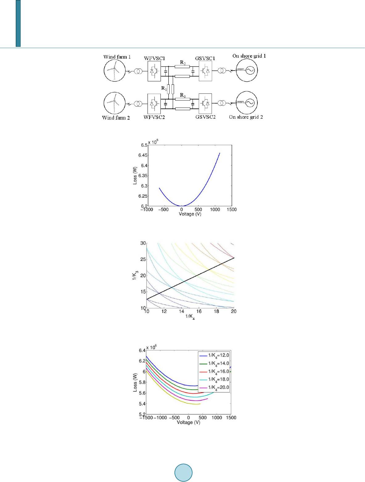 X. D. Zhao et al. Figure 6 . A four-terminal HVDC network simulation. Figure 7. Transmission loss via voltage differ- ence between two GSVSCs. Figure 8. Two GSVSCs DC voltage change via droop parameter. Figure 9. Transmission loss variation via vol t- age difference between two GSVSCs. 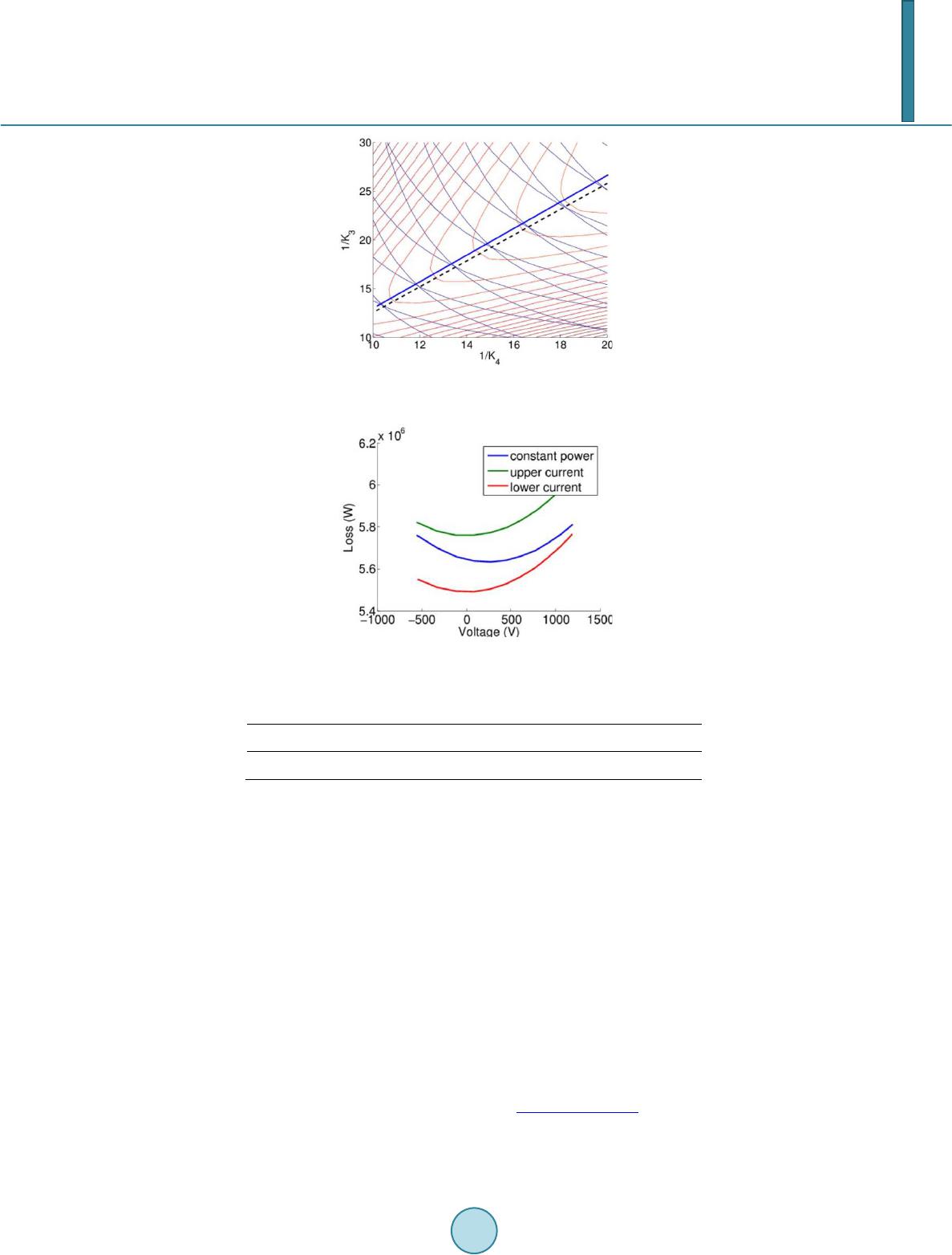 X. D. Zhao et al. Figure 10. GSVSCs DC voltage change via droop parameters. Figure 11. Power loss range bounded by upper and lower current. Table 1. Simulation parameters. Base voltage WF1 po wer WF2 power R1 R2 R3 400e3 V 600 MW 400 MW 0.5 Ω 1.2 Ω 0.8 Ω 6. Conclusion In this paper, three different c onfi g ur a tio ns of a four terminal HVDC network have been i nve s ti ga ted to achieve minimal transmission loss using voltage droop control. The effect of grid side DC voltage change on the trans- mission loss has been analysed. It is found that in order to achieve the minimal transmission loss the grid side DC voltage should be equal with an ideal constant current input from the wind farm side. However, when the wind farm side VSC works in constant power mode, this requirement will change due to the power characteristic of the wind farm power injection. Simulations have been carried out in Simulink and the analysis is verified by simulation results. Acknowledgements X. Zhao would like to thank Chinese Scholarship Council (CSC) for sponsoring his research at Queen's Univer- sity Belfast. The work is partially funded by the EPSRC under grants EP/L001063/1 and EP/G042594/1. References [1] E.W.E. Association and Others (2005) Wind Force 12 . CA. http://www.ewea.org [2] Wikipedia, European super grid. [3] Bresest i, P., Klin g, W. L. , Hend riks, R.L. and Vailati, R. (20 07) HVDC Connection of Offshore Wind Farms to the  X. D. Zhao et al. Transmission System. IEEE Transactions on Energy Conversion, 22, 37-43. http://dx.doi.org/10.1109/TEC.2006.889624 [4] Xu, L. and Yao, L. (2011) DC Voltage Control and Power Dispatch of a Mu l ti -Terminal HVDC System fo r Integrating Large Offshore Wind Farms. IET Renewable Power Generation, 5, 223. http://dx.doi.org/10.1049/iet-rpg.2010.0118 [5] Hail eselassi e, T. M. and Uhlen, K. (2012 ) Impact of DC Line Voltage Drops on Power Flow of MTDC Using Droop Control. IEEE Transactions on Power Systems, 27, 1441-14 49 . http://dx.doi.org/10.1109/TPWRS.2012.2186988 [6] Xu, L., Yao, L. , Bazargan, M. and Yao, L. (2009 ) DC Grid Management of a Multi-Terminal HVDC Transmission System for Large Offshore Wind Farms. 2009 International Conference on Sustainable Power Generation and Supply, 1-7. [7] Abdel-Khalik, A.S., Massoud, A.M., Elserougi, A.A. and Ahmed, S. (2013) Optimum Power Transmission-Based Droop Control Design for Multi-Terminal HVDC of Offshore Wind Farms. IEEE Transactions on Power Systems, 28, 3401-3409. http://dx.doi.org/10.1109/TPWRS.2013.2238685 [8] Daele mans, G. , Srivastava, K., Reza, M., Cole, S. and Belmans, R. (20 09 ) Minimization of Steady-State Losses in Meshed Networks Using VSC HVDC. IEEE Po we r & Energy Society General Meeting, 1-5. [9] Beert en, J., Cole, S. and Belmans, R. (2010) A Sequential AC / D C Power Flow Algorithm for Networks Containing Multi-Terminal VSC HVDC Systems . IEEE Power and Energy Society General Meeting, 1-7. [10] Cao, J., Du, W., Wang, H.F. and Bu, S. (2013) Minimization of Transmission Loss in Meshed AC/DC Grids with VSC-MTDC Networks. IEEE Transactions on Power Systems. http://dx.doi.org/10.1109/TPWRS.2013.2241086 [11] Aragüé s -P eñalb a, M. , Egea-Alvar e z , A. , Gomis-Bellmunt, O. and Sumper, A. (2012) Optimum Voltage Control for Loss Minimization in HVDC Multi-Terminal Transmission Systems for Large Offshore Wind Farms. Electric Power Systems Research, 89, 54-63 . http://dx.doi.org/10.1016/j.epsr.2012.02.006 [12] Lian g , J., Gomis-Bellmunt, O., Ekan a yake, J., Jenkins, N. and An, W. (2012) A Multi-Terminal HVDC Transmission System for Offshore Wind Farms with Induction Generators. International Journal of Electrical Power & Energy Sys- tems, 43, 54-62. http://dx.doi.org/10.1016/j.ijepes.2012.04.063 [13] Gomi s-Bellmunt, O., Liang, J., Ekanayake, J. and Jenkins, N. (20 11) Voltage-Current Characteristics of Multiterminal HVDC-VSC for Offshore Wind Farms. Electric Power Systems Research, 81 , 440-450. http://dx.doi.org/10.1016/j.epsr.2010.10.007
|