 Journal of Power and Energy Engineering, 2014, 2, 280-287 Published Online April 2014 in SciRes. http://www.scirp.org/journal/jpee http://dx.doi.org/10.4236/jpee.2014.24039 How to cite this paper: Li, X.M., Feng, L., Tang, Y. and Chen, Y.H. (2014) Fuzzy Decision Method Applied in Action of Reactive Power Compensation Devices in Wind System. Journal of Power and Energy Engineering, 2, 280-287. http://dx.doi.org/10.4236/jpee.2014.24039 Fuzzy Decision Method Applied in Action of Reactive Power Compensation Devices in Wind System Xueming Li1, Li Feng2, Yi Tang2, Yonghua Chen1 1NARI Group Corporation, Nanjing, China 2School of Electrical Engineering, Southeast University, Nanjing, China Email: lixueming@sg epri.sgcc.com.cn , lfseuee@163.com, tangyi@seu.edu.cn, chenyonghua@sgepri.sgcc.com.cn Received January 2014 Abstract Frequent occurrence of large-scale cascading trip-off of wind turbine raises the concern about the decision process of ordered control of reactive power compensation devices. The theory of fuzzy multi-attribute decision making is adopted to ascertain the action sequence of reactive power compensation devices. First, a set of evaluation indexes including control sensitivity, regulation margin, response time, response level and cost is set up, and fuzziness of the proposed qualitative indexes is introduced to make them com parable to the proposed quantitative indexes. Then a method to calculate fuzzy weight of each index is put forward for evaluating relative importance of the proposed indexes. Finally, the action sequence of reactive power compensation devices is de- termined through the theory of fuzzy compromise decision making. The case study shows that the proposed method is effective to obtain the action sequence of reactive power compensation de- vices which correspond to experience. Keywords Wind Power System; Reactive Power Compensation Device; Ordered Control; Fuzzy Multi-Attribute Decision Making; Evaluation Index 1. Introduction With the development of new energy, the amount of wind power system combined to power gird is increasing. However, the large-scale connection of wind farms with power grid has adverse effect on the safety of power grid [1-3]. In consideration of China’s large-scale centralized development of wind power [4], reactive and vol- tage problems deserve more attention. According to requests of China’s relevant standards in wind power com- bined to power grid such as Q/GDW392-2009, GB/T19963-2011, power system should be able to take part in reactive and voltage control and contain reactive power compensation devices [5]. Equipment like variable speed-constant frequency WTGS, Static Var Compensator (SVC), Static Synchronous Compensator (STATCOM), On Load Tap Changing transformer (OLTC), fixed-switchable shunt capacitors can be used in wind power sys-  X. M. Li et al. tem to release reactive power and obviously these equipment have different dynamic responsive characteristics. Reactive power compensation device taking preset actions according to local electric parameters data is a commonly used control strategy in grid. This control strategy is simple enough to put to use and works well in traditional grid. Nevertheless, this strategy doesn’t take action sequence into account which possibly leads to severe security and stability issues in grid combined with wind power system. For example, several large-scale cascading trip-off of wind turbine happening in 2011 are caused by unordered regulation and actions of reactive power compensation device to a large extent [6]. Hence, a control strategy considering action sequence of vari- ous reactive power compensation devices is desperately needed. It is an important step to evaluate reactive power compensation devices reasonably when designing control strategy for reactive power compensation devices due to different reactive power compensation device require- ments in different power system state. For example, regulation economy comes first in all considered factors when power system is in a good state and when power system is in fault state, recovering the power system as soon as possible is most important. This paper aims to achieve the latter requirement and mainly talks about the action sequence of various reactive power compensation devices in wind power system when a fault happened in power system. As the basis of determining various reactive power compensation devices’ action sequence, it is necessary to find out a variety characteristics of reactive power compensation device and relative importance of these cha- racteristics. Besides this, it is rather difficult to transform all kinds of fuzzy concepts reasonably and take each index into account synthetically. In order to solve the difficulty, fuzzy multi-attribute decision making theory which shows great effects in power system research is involved in this paper. Fuzzy multi-attribute decision making theory has been successfully applied to power system research such as making black-start scheme [7], making equipment maintenance strategy [8], evaluating high voltage transmission mode [9] and so on. First of all, this paper proposes influence factors need to be considered when making action sequence of reactive power compensation devices and quantifies qualitative index with fuzzy number. Then action sequence is determined through the theory of fuzzy compromise decision making. Finally this proposed method is applied to a simula- tion case and works out an action sequence of reactive power compensation devices. 2. Index System for Determining Action Sequence 2.1. Principal Factor of Wind Power System’s Reactive Power Regulation This paper identifies factors from two aspects. On one hand characteristics of reactive power compensation de- vices used in wind farm are taken into consideration such as response time, regulation level and cost etc. On the other hand the effect on power gird that reactive power compensation devices have should also be considered such as voltage regulation ability, impact on other nodes when voltage regulation and so on. From above several important factors of wind power system’s reactive power and voltage regulation are listed below: 1) Voltage of nodes in power system can be regulated by controlling reactive power compensation device for example switching control of compensation capacitors and STATCOM. It is obvious that regulation effects are different because nodes in different electric position have different regulation sensitivity. In order to find out most effective control variable, sensitivity of control variable can be calculated by voltage reactive sensitivity method. 2) Regulation margin is an important index because of limiting conditions of device and operation condition such as voltage limit of wind farm’s terminal, capacity limit of shunt capacitor bank, regulating range limit of voltage regulating transformer, regulating variable limit of SVC and STATCOM. 3) Different control variable has different dynamic operating characteristics, so difference in response time is rather big. The requirement of response time is severe when fault happened in power grid because voltage must be regulated back to normal quickly. 4) Response degree of control variables is different from each other after they changed because of effects of power system’s run- state. This index can only be evaluated qualitatively considering that real-time state of grid changes too fast to be measured. 5) Considering cost and self-character, running cost of control variables is different because of different added losses and fault rate. When fault happens, running cost is an unvalued index in most cases. Index (1), index (2) and index (3) are quantitative indexes according to description of each index above. These three factors usually can be ascertained by off-line calculation or real-time data acquisition and dynamic 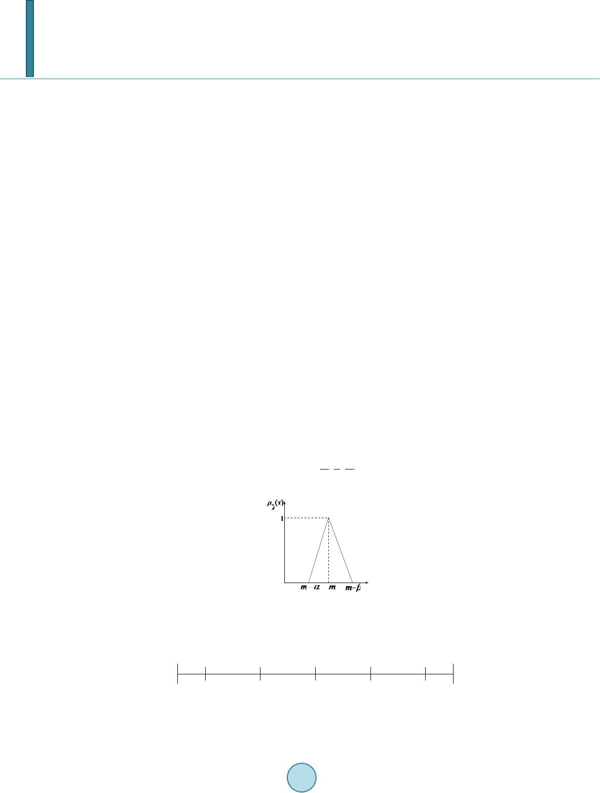 X. M. Li et al. updating for example index (1) can be figured out by network topology and operation mode and index (2), (3) can be directly got by surveying operation condition and intrinsic parameter of device. Index (4) and index (5) are connected with operation condition of gird network which means they hardly can be quantified directly. Considering this characteristic of index (4) and (5), fuzzy number concept is involved in this paper and it is used as a tool to transform qualitative data into math expression. 2.2. Expression of Qualitative and Quantitative Index As previously mentioned, index (4) and index (5) can’t be shown as accurate math expression directly while concept of triangular fuzzy number [10] is helpful to solve this problem. Usually expression of triangular fuzzy number is written as (or , , ). and are recognized as left and right diffusion of fuzzy number and fuzzy number is shown as below: It is easily to transform ordinary number into triangular fuzzy number by set and the expression is . In order to quantify index (4) and (5), Bipolar Scaling proposed by MacCrimmon is used in this paper and its transforming method is shown in Figure 1. In Figure 2, index is divided as earnings index and cost index and there is a one-to-one correspondence be- tween importance level and quantitative data. By analyzing definitions of index (4) and (5), index (4) is judged as earnings index while index (5) is cost index. Both of index (4) and (5) can be transformed into triangular fuzzy number by determining their importance level. 2.3. Weight Analysis Determining weight value for each index is an important step before making compound decision while decision maker usually can’t set accurate weight value for each index by his experience. Under this circumstances, this paper assumes that decision maker know the relative importance of indexes which contributes to working out each index’s weight value in triangular fuzzy number form. By referring to document [10], calculation method is concluded and shown in Table 1. 1) Construct fuzzy reciprocal matrix. Element of this matrix is determined by rule of quantization which is shown below. For example if index I is more important than index j then set where and represents fuzzy level of this judgment. It assumes that in this paper. Since the value for index I to j is determined, the value for index j to I is 1111 ,, 5 ji ijij ij ww lr − == . Then fuzzy reciprocal matrix Figure 1. Form of triangular fuzzy number. Figure 2. Bipolar scaling. (0.0,0.0,0.1) (0.0,0.1,0.2)(0.2,0.3,0.4) (0.4,0.5,0.6)(0.6,0.7,0.8)(0.8,0.9,1.0) (0.9,1.0,1.0) cost earnings MH VH H medium L VL ML ML VL L medium H VH MH  X. M. Li et al. Table 1. Rule of quantization. Relative important degree 1 3 5 7 9 i compared with j equally important Little More important important obviously important absolutely important can be constructed with this method. 2) Work out weight value for each index. Weight value for each index can be calculated by following formu- la. 1 1 1 1 1 1 1 1 1 nn n i iji i j nn n i iji i j nn n i iji i j l lll m m mm r rrr = = = = = = = = = = = = ∑ ∏ ∑ ∏ ∑ ∏ Then weight value for index I is . 3. Fuzzy Multi-Attribute Decision Making Theory Applied in Wind Power System’s Reactive Power Compensation Device Action Plan Optimization It assumes that available reactive power compensation devices set is and from 1.1, indexes set considered in determining action sequence of reactive power compensation devices can be represented as . According to reactive power compensation devices set and indexes set, a full matrix can be constructed. represents value for index and reactive power compensation device . As is mentioned in 1.3 weight value matrix for each index is and represents weight value for index . In this paper, fuzzy ideal solution ( ) and fuzzy negative ideal solution ( ) are used as reference stan- dard. Satisfaction concept is introduced to help measure the difference between action plan and fuzzy ideal solu- tion. After calculating satisfaction value for each device’s index, satisfaction value for each device can be fig- ured out by weighted sum with weight value matrix . Finally, action sequence of reactive power compensation devices can be listed by comparing devices’ satisfaction value each other. Step 1: Fuzzy ideal solution and fuzzy negative ideal solution Fuzzy ideal solution is a set made up of optimal index value in all considered devices. Because of the differ- ence between earnings index and cost index, the way to work out fuzzy ideal solution is different. Take fuzzy index for example and its choosing method is shown in Table 2. Accurate number shares the same method. For fuzzy negative ideal solution, its definition is similar to fuzzy ideal solution which means they have a similar way to worked out. Step 2: Satisfaction matrix with fuzzy weight This is defined as the satisfaction of action device to index . For a fuzzy number, its calculating formu- la is defined as follows: () () () () ,, ,, L ijLjLR ijRjR ij LjL jLRjR jR dxMdxM dM MdM M λ −− +− +− + =+ repres ents hamming distance between and . Multiply satisfaction matrix by weight value matrix and get weighted satisfaction matrix :  X. M. Li et al. Table 2. Method of calculating fuzzy ideal solution. categories Fuzzy ideal solution Membership function earnings ( ) ( ) ( )() ( ) 12 12 12 12 , ,, ,, sup min, jj jmmmj m xx Mxx xxm x xxxR xx xx µµ µµ + =∧∧∧ ∈ = cost () () ()( ) () 12 12 12 12 , ,, ,, sup min, jj jmmmj m xx Mxx xxm x xxxR xx xx µµ µµ + =∧∧∧ ∈ = So the weighted satisfaction matrix can be written as: . Step 3: Determine preferred value is defined as weighted sum of satisfaction value of action device and it can be calculated by follow- ing formula: 12 ,5 Tww w i iiin n λλλ λ =⊕ ⊕⊕= represents general addition of fuzzy number and its membership function is : ( ) ( ) ( ) ( ) ( ) { } 1 121 2 12 1 , ,, , ,, supmin, , T ww ii in nn n n xxxx xx xxx R x xx λ λλ µ µµ =+ ++ ∈ = After getting , greatest fuzzy set and minimal fuzzy set can be determined and their membership function can be defined as follows: ( ) ( ) ( ) ( )() ( ) { } ~12 12 12 12 max , ,, supmin,, , TT T Tm im m n m xx xx xxx R xxx x λλ λ λ µµµ µ =∨ ∨∨ ∈ = ( ) ( ) ( ) ( )() ( ) { } ~12 12 12 12 min , ,, supmin,, , TT T Tm im m n m xx xx xxx R xxx x λλ λ λ µµµ µ =∧ ∧∧ ∈ = Relative utility function can be calculated by membership formula: ( ) () ( )( ) ()( )()( ) ~~ ~~ ~~ ,min ,min max ,minmax,min T i TT TT L iLiLR iRiR fTT TT LiLiL RiRiR dd r dd λ λλ λλ µ λλ λλ + = + Finally the action sequence of reactive power compensation device is worked out by ranking the value of from largest to smallest. 4. Simulation Case In Figure 3, there are several reactive power compensation devices like MCR-SVC, TCR-SVC, fixed capacitor and STATCOM in this local grid. Besides this, this local grid includes wind power system which adds difficulty in regulating voltage and reactive power. In this simulation case, it assumes that a fault happened in power sys- tem and switch off reactive power compensation devices to clear up overvoltage. So in this paper it is aim to de- termine the action sequence of reactive power compensation devices to regulate voltage back to normal as soon as possible (Table 3). Decision-making matrix can be calculated with method in 1.2. ( )( ) ( )( ) ( )() ( )( ) ( )( ) ( ) ~ 0.002830.4,0.5,0.644 0.10.4,0.5,0.6 0.0008090.6,0.7,0.8880.030.2,0.3,0.4 0.0008450.8,0.9,1.011 0.010.0,0.1,0.2 0.00007280.6,0.7,0.8220.030.2,0.3,0.4 0.002820.6,0.7,0.8460.030.2,0.3,0.4 0.000806 0.2,0.3,0.4 D= ( ) 100 10.8,0.9,1.0 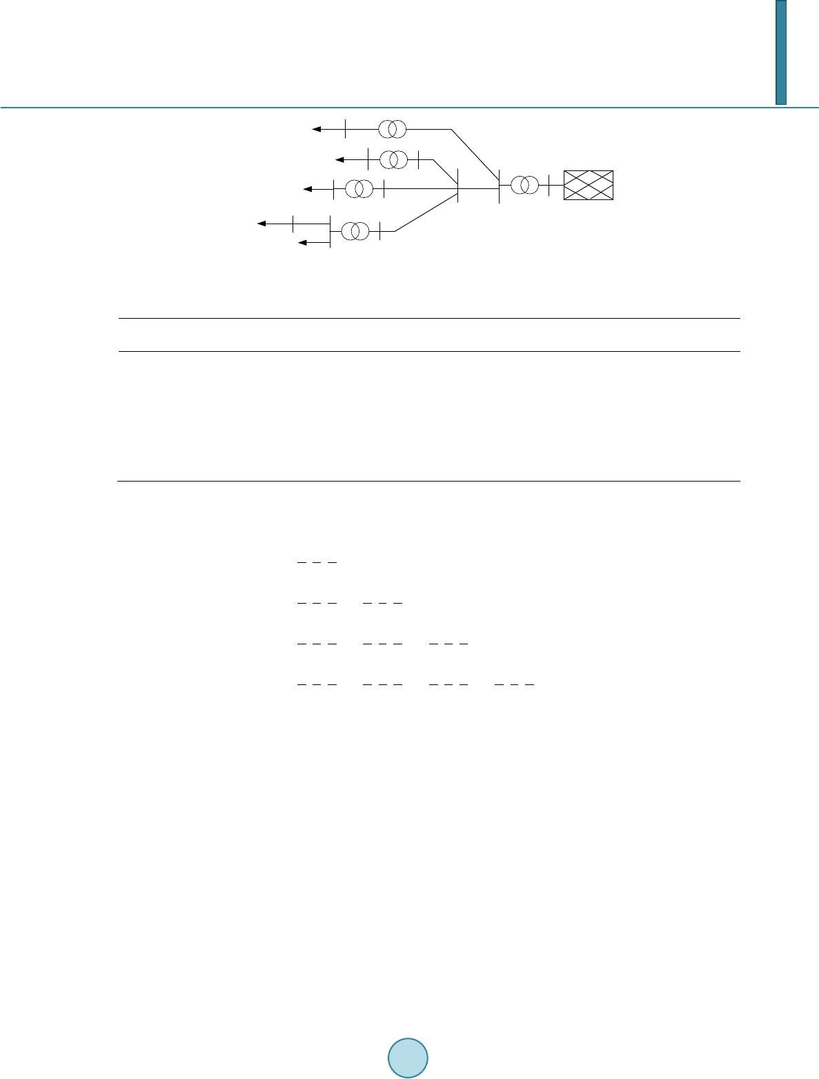 X. M. Li et al. Figure 3. Structure of simulation case. Table 3. Attributes of reactive power compensation devices. nodes Device classification Sensitivity of regulating voltage p.u./Mvar response degree response time Output reactive power/Mvar response cost 1 MCR-SVC 0.00283 me 0.1 44 me 4 TCR-SVC 0.000809 H 0.03 88 VH 3 STATCOM 0.000845 VH 0.01 11 H 5 TCR-SVC 0.0000728 H 0.03 22 VH 2 TCR-SVC 0.00282 H 0.01 46 VH 9 FC 0.000806 L 1 100 L According to rule of quantization fuzzy reciprocal matrix is set up. ()( )()()() ( )( )( )() ()() () ()() 1,1,12,3,4 2,3,4 2,3,44,5,6 111 , ,1,1,12,3,42,3,44,5,6 234 111 111 ,,,,1,1,12, 3,44,5,6 234 234 111 111 111 ,,,,,,1,1,1 4,5,6 234 234 234 111 111 111 1 ,, ,, ,, 456 456 456 4 = W ( ) 11 , ,1,1,1 56 Since fuzzy reciprocal matrix is set up, weight for each index can be calculated. () () ()() () 0.28,0.41,0.57 ,0.21,0.27,0.32 ,0.16,0.17,0.18 ,0.10,0.11,0.12 , 0.03,0.04,0.05w= Fuzzy ideal solution and fuzzy negative ideal solution can be found out by using method mentioned in 2.2. ( )( ) 0.00283, 0.8,0.9,1.0 ,100,1,0.8,0.9,1.0M + = () () 0.0000728, 0.2,0.3,0.4 ,11,0.01, 0.0,0.1,0.2M − = Relative satisfaction matrix is set up and shown as follows. 10.30.371 0.0910.5 0.2670.5 0.865 0.0200.25 0.280 0.7000 00.5 0.1240.020 0.25 0.9960.5 0.393 0.020 0.25 0.266 0111 ij λ == λ 风电场群1-1 风电场群3 风电场群2 风电场群4 无穷大电网 汇集站 D525母线 汇集站 D230母线 汇集站 B230母线 风电场群1-2 1 2 3 4 5 6 7 8 9 1011  X. M. Li et al. Weighted satisfaction matrix is worked out easily. ()() () () () () ( ) ( ) () () 0.28,0.41,0.570.063,0.081,0.096 0.060,0.063,0.067 0.075,0.109,0.152 0.105,0.135,0.16 0.138,0.147,0.156 0.078,0.115,0.160 0 00.105,0.135,0.16 0.020,0.021,0.022 0.279,0 0.147,0.189,0.224 w ijj ij w λλ = = = ⊗ w λ ()() () ()( ) () () () () () () .408,0.568 0.105,0.135,0.160.063,0.067,0.071 0.074,0.109,0.152 00.16,0.17,0.18 0.009,0.010,0.011 0.015,0.020,0.025 0.002,0.0022,0.0024 0.008,0.010,0.013 00 0.002,0.0022,0.0024 0.008,0.010,0.013 0.002,0 () () () () .0022,0.0024 0.008,0.010,0.013 0.10,0.11,0.12 0.03,0.04,0.05 1) Sum weighted matrix can be worked out. ( ) ( ) ( ) ( ) ( ) ( ) 0.508 0.584 0.769 0.328 0.403 0.483 0.225 0.304 0.384 =0.135,0.168,0.197 0.457 0.622 0.814 0.364,0.429,0.502 T i λ , , , , , , , , 2) Finally relative utility function can be figured out with . ( ) 0.911 0.405 0.216 =0.106 0.789 0.998 f T i λ By ranking from largest to smallest, the action sequence of reactive power compensation devices is determined. The action sequence is: fixed capacitor at pooling station B230, MCR-SVC at wind farm 1, TCR-SVC at wind farm 1, TCR-SVC at wind farm 2, STATCOM at wind farm 3 and TCR-SVC at wind farm 4. 5. Conclusion This paper proposes a method to determine action sequence of reactive power compensation devices in wind power system at the time of voltage regulating. Characteristics of reactive power compensation devices have impact on grid and these characteristics include qualitative index and quantitative index which can’t be eva- luated by a certain judging standard. Fuzzy theory is introduced in this paper to solve this problem. Each index of reactive power compensation device can be expressed perfectly with fuzzy multi-attribute decision making theory and by using this theory result corresponds to real condition more accurately. References [1] Hao, Z.H. and Yu, Y.X. (2011) The Influence of Doubly -Fed Induction Generator on Stability of Power System. Pow- er System Protection and Control, 39, 7-11.  X. M. Li et al. [2] Huang, X.L., Liu, Z.R., Zhu, R.J., et al. (2010) Impact of Power System Integrated with Large Capacity of Variable Speed Constant Frequency Wind Turbines. Transactions of China Electrotechnical Society, 24, 142-149. [3] Ni, L., Yuan, R.X., Zhang, Z.B. and Liu, C. (2011) Research on Control Method and Dynamic Characteristic of Large Wind Farm Integration. Power System Protection and Control, 39, 75-81. [4] Yin, M., Wang, C.S., Ge, X.B. and Zhang, Y.B. (2010) Comparison and Analysis of Wind Power Development be- tween China and Germany. Transactions of China Electrotechnical Society, 25, 157-164. [5] Jiang, W., Yan, Z. and Yang, J.L. (2010) Reliability Assessment of Composite Generation and Transmission System Considering Wind Farms. Power System Protection and Control, 38, 126-130. [6] He, S.E. and Dong, X.Z. (2012) Cause Analysis on Large-Scale Wind Turbine Tripping and Its Countermeasures. Power System Protection and Control, 40, 131-137. [7] Zhang, Z.Y. and Chen, Y.P. (2007) Optimization of Power System Black-start Schemes Based on the Fuzzy Multiple Attribute Decision-Making Method . High Voltage Engineering, 33, 42-45. [8] Yuan, Z.J. , Sun , C.X. , Li, J., et al. (2004) Study on Condition-Based Maintenance Policy of Transformer Based on Fuzzy Multiple Expert and Multiple Attribute Group Decision Making. Automation of Electric Power Systems, 28, 66- 70. [9] Dai, S.Y. and Peng, X. T., et al. (2012) Comprehensive Evaluation Method of Ultra High Voltage Transmission Modes Based on Fuzzy Optimization. High Voltage Engineering, 38, 3316-3322. [10] Li, R.J. (2002) Fuzzy Multi-Attribute Decision Making. Fuzzy Multi-Attribute Decision Making Theory and Applica- tion. Science Publishing House, Beijing, 138-200.
|