 Journal of Power and Energy Engineering, 2014, 2, 47-52 Published Online April 2014 in SciRes. http://www.scirp.org/journal/jpee http://dx.doi.org/10.4236/jpee.2014.24007 How to cite this paper: Miyaji, T., Kasahara, R., Kanemoto, T., Kim, J.-H., Choi, Y.-S. and Umekage, T. (2014) Power Stabilization System with Counter-Rotating Type Pump-Turbine Unit for Renewable Energy. Journal of Power and Energy Engineering, 2, 47-52. http://dx.doi.org/10.4236/jpee.2014.24007 Power Stabilization System with Counter-Rotating Type Pump-Turbine Unit for Renewable Energy Toru Miyaji1*, Risa Kasahara1, Toshiaki Kanemoto2, Jin-Hyuk Kim3, Young-Seok Choi3, Toshihiko Umekage2 1Graduate School of Engineering, Kyushu Institute of Technology, Fukuoka, Japan 2Faculty of Engineering, Kyushu Institute of Technology, Fukuoka, Japan 3Green Energy System Technology Center, Korea Institute of Industrial Technology, Cheonan, Korea Email: *n344154t@tobata.isc.kyutech.ac.jp Received December 2013 Abstract Traditional type pumped storage system contributes to adjust the electric power unbalance between day and night, in general. The pump-turbine unit is prepared for the power stabilization system, in this serial research, to provide the constant power with good quality for the grid system, even at the suddenly fluctuating/turbulent output from renewable energies. In the unit, the angular momentum changes through the front impeller/runner must be the same as that through the rear impeller/runner, that is, the axial flow at the outlet should be the same to the axial flow at the inlet. Such flow conditions are advantageous to work at not only the pumping mode but also the turbine mode. This work discusses experimentally the performance of the unit, and verifies that this type unit is very effective to both operating modes. Keywords Power Stabilization; Pump-Turbine; Counter-Rotation; Impeller; Generator Motor 1. Introduction To contribute preventing the global warming, the efficient use of clean energy resources, such as a solar power, a wind power and so on, is indispensable, while the electric power is provided steadily for the grid system. In this serial research, a power stabilization system with a counter-rotating type pump-turbine unit is devel- oped for providing instantaneously the constant output to the grid system. In the pump-turbine unit, front and rear impellers/runners rotate conversely, inner and outer armatures also counter-rotate at the same torque. In the pumping mode, the rotating speeds of both the impellers are adjusted automatically by the smart control. Hence, the unstable characteristic and cavitation can be suppressed effectively [1]. Moreover, the unit in the turbine mode has fruitful advantages that not only the induced voltage is sufficiently high without supplementary *Corresponding author. 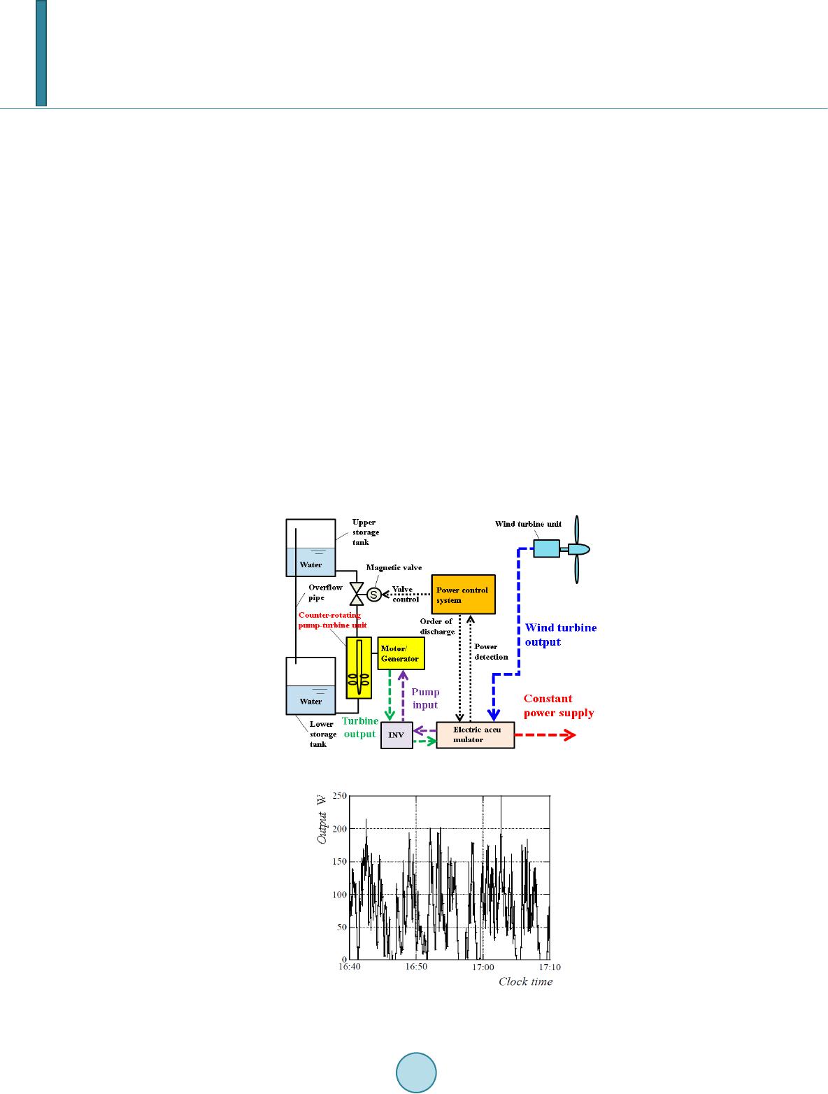 T. Miyaji et al. equipment such as a gearbox, but also the rotational moment hardly acts on the mounting bed because the rota- tional torque is counter-balanced in the armatures/runners [2]. In this paper, the hydrodynamic performance of the pump-turbine unit with the counter-rotating type impellers designed exclusively for pump mode is investi- gated experimentally in the power stabilization system. 2. Power Stabilization System with Pumped Storage Figure 1 shows the diagram of the power stabilization system with the counter-rotating type pump-turbine unit. The system is mainly composed of the electric accumulator with the minimal capacity, the power control device, and counter-rotating type pump-turbine unit. As the wind power station is the most distinctive for the unstable and fluctuating output among the renewable energy resources, it was applied as an example for the power stabilization system of this work. Figure 2 shows the output from field tests of the intelligent wind power unit in house works [3], and its output was averaged every one minute as shown in Figure 3, where the average output is arbitrarily 16,000 times as high as one in Figure 2. It is assumed conveniently, here, that the wind power station should provide the constant power PG of 1 MW for the grid system. The output from the wind power unit connects directly to the electric accumulator, and the power control device detects that the output is higher or lower than PG. The power control device de- mands the electric accumulator not only to provide the constant power PG for grid system but also to operate the pump-turbine unit at the pumping mode by the surplus power, while the wind velocity is faster than that giving PG, as shown in Figures 1 and 3. That is, the surplus output is stored, at once, as the potential energy by the pumping mode. On the contrary, as shown in the same figures, the power control device demands the pump-turbine unit to operate at the turbine mode converting from the stored potential energy to the hydroelectric output, so as to take PG with accompanying the shortage output from the wind power unit. Then, the pumping Figure 1. Power stabilization system. Figure 2. Output from the wind power unit in house. 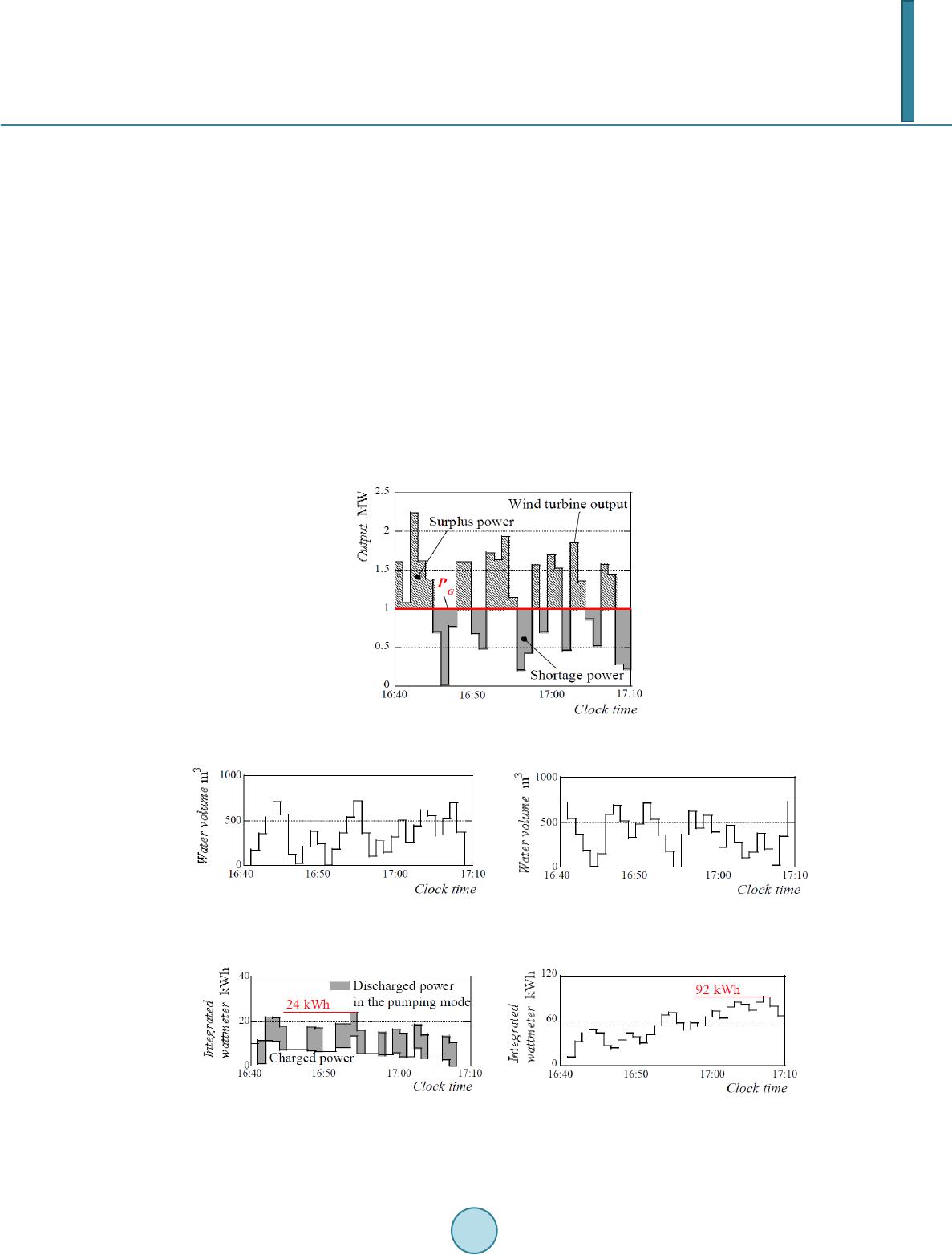 T. Miyaji et al. mode or the turbine mode is instantaneously operated in the alternative every one minute in Figure 3, judging the output from the wind power unit. The final target of this serial work is to make average time short as possi- ble. Figure 4 shows the water volume of the upper and the lower storage tanks in the power stabilization system while operated just above. Moreover, Figure 5 shows the integrated wattmeter in the accumulator, where the pumping/turbine head is 15 m, the input is 625 kW at the pumping mode, and the hydroelectric output is ad- justed to guarantee PG in response to the output from the wind power unit. The electrical accumulator re- quires the capacity up to 24 kWh as shown in Figure 5(a), while the power stabilization system operates in Figure 4. The capacity 24 kWh is 1 - 8th of the capacity of the electrical accumulator installed traditionally in the wind power station without the proposed stabilization system, as confirmed in Figure 5. To put the above stabiliza- tion system into the practical use, the suitable pump-turbine unit suitable for above operations should be pre- pared. 3. Counter-Rotating Type Pump-Turbine Unit 3.1. Model Unit The unit designed exclusive for the pumping mode, which is very important for the pumped storage, was Figure 3. Resultant output averaged every 1 minute. (a) (b) Figure 4. Water volume in the storage tanks. (a) Upper storage tank; (b) Lower storage tank. (a) (b) Figure 5. Capacity in the electric accumulator. (a) With power stabilization system; (b) Without power stabilization system. 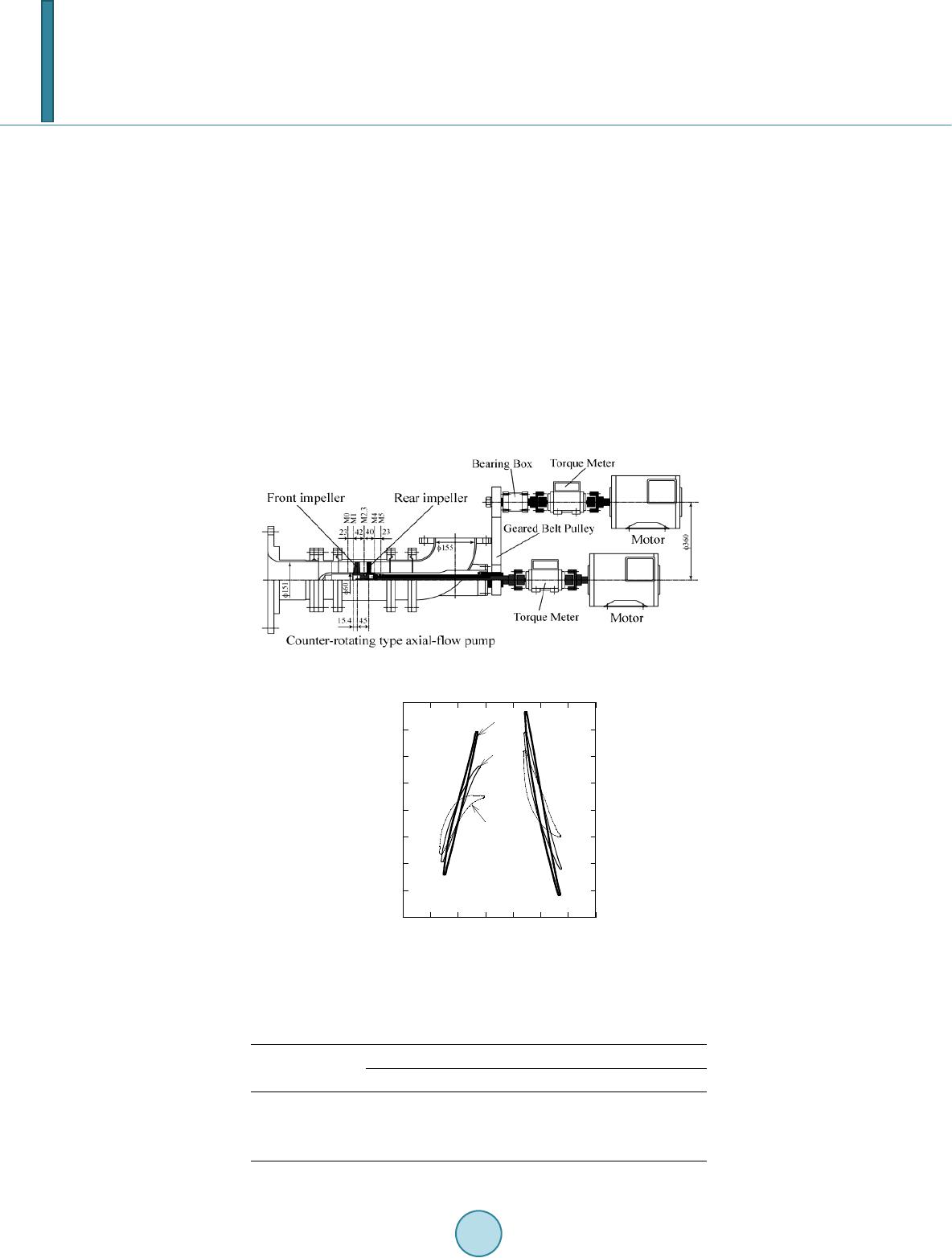 T. Miyaji et al. prepared for the preliminary experiments. Figure 6 shows the counter-rotating type axial-flow pump unit. The major specifications at the normal operation are the theoretical head HET = 4.4 m, the discharge Q = 1.78 m3/min, the individual impeller speed nF = nR = 1500 min−1 (subscripts F and R denote the front and the rear impellers). The specific speed of the individual impeller is NS = 1100 m, m3/min, min-1, and the specific speed as the pump- ing unit with the counter-rotating type impellers is NST = 1320 m, m3/min, min−1. The impeller diameters D are 150 mm, and the boss ratio is 0.4. 3.2. Counter-Rotating Type Impellers The blade profiles of this unit are shown in Figure 7 and its dimensions are given in Table 1, where RQ and Z are the distances in the circumferential/tangential and the axial directions divided by D, and bd is the inlet and the outlet angles of the blades measured from the axial direction (subscript 1 to 4 denote the inlet and the outlet of the front and rear impellers, respectively). The numbers of the front and rear blades are 5 and 4 in the pumping mode (the numbers of the front and the rear blades are 4 and 5 in the turbine mode). Impeller/Runner B used in the experiments was designed by the three-dimensional inverse method to improve the exclusively pump performance [4]. Figure 6. Trail model of the counter-rotating type pump turbine unit. -0.4 -0.3 -0.2 -0.1 0.0 0.1 0.2 0.3 0.4 -0.2 -0.10.0 0.1 0.2 0.3 0.40.5 Front impeller blade Impeller B Mean plane Hub plane Tip plane Rear impeller blade Circumferential direction R Θ Axial direction Z Figure 7. Blade profiles of the counter-rotating type impeller. Table 1. Blade angles and solidities. Impeller Blade angle (deg.) Solidity βd1 βd2 βd3 βd4 Front Rear B Hub −76.9 −14.9 71.9 42.9 0.99 0.89 Mean −79.2 −58.0 77.2 70.1 0.82 0.82 Tip −80.4 −79.0 79.9 75.9 0.81 0.78 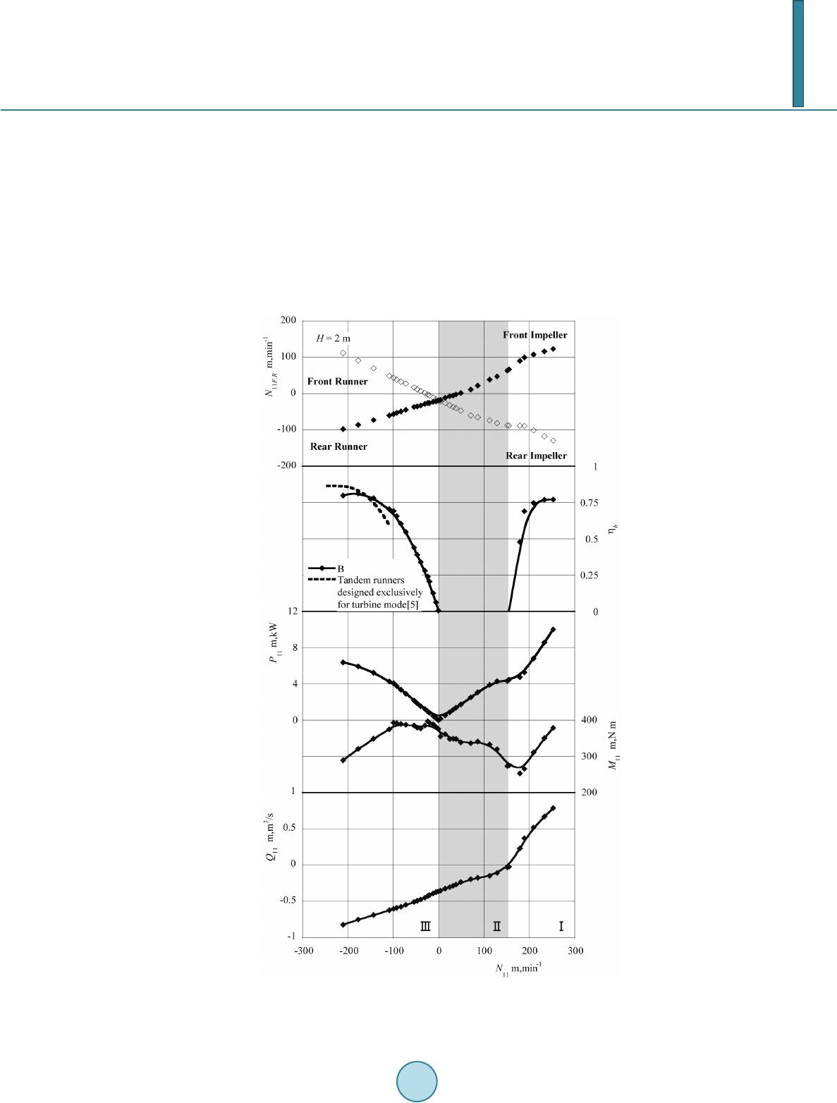 T. Miyaji et al. 4. Performance Figure 8 shows the unit discharge Q11[= Q/(D2H1/2)], unit torque M11[= M/(D3H)], unit input or the output P11[= P/(D2H3/2)], the hydraulic efficiencies in the pumping mode hh[=rgQH/P], and the turbine mode hh[= P/(rg Q H)], the unit rotational speeds of the front and the rear impellers/runners N11 F,R(= nF,RD/H1/2), and the unit relative rotational speed N11(= nD/H1/2), while the head is kept constant H = 2 m. The water is pumped up while the discharge Q11 is positive at the positive N11 and Q11, which is called the pumping area (I). It is necessary to make the rotational speed N11 faster than 150 m, min−1, for pumping up. The slower rotational speed cannot pump up, because the pump head is in proportion to the square rotational speed. Therefore, the braking area (II) exists where Q11 is negative even at the positive N11. The negative rotational speed is in the turbine mode (III). That is, the rotational speed must be increased rapidly when the operation changes from the turbine to the pumping Figure 8. Overall performances of the counter-rotating type pump-turbine unit.  T. Miyaji et al. modes. In Q11 = −0.45 ~ −0.35 m, min−1 at the turbine mode, the front runner N11F rotates in the same direction as the rear runner N11R but faster than N11R to take the output. The hydraulic efficiency is maximum at the mo- derate rotational speed, and the value nearly corresponds to the efficiency (the dot line) of the counter-rotating type hydroelectric unit designed exclusively for turbine mode [5]. These results suggest that this type unit has greatly effective performance for both pumping and the turbine modes. 5. Conclusion The power stabilization system with the counter-rotating type pump-turbine unit was proposed to provide the constant power with high quality for the grid system. The hydrodynamic performance of the counter-rotating type pump-turbine unit with the impellers designed exclusively for pumping mode was also investigated experimentally, and proved beneficial operation at not only the pumping but also the turbine modes. References [1] Kanemoto, T., Kimura, S. , Ohba, S. and Satoh, M. (2000) Smart Control of Axial Flow Pump Performances by Means of Counter-Rotating Type (1st Report, Counter-Rotating Type and Performances). JSME , Series B, 66, 2927-2933. (in Japanese) http://dx.doi.org/10.1299/kikaib.66.651_2927 [2] Kanemoto, T., Tana ka, D. , Kashiwab ara, T., Uno, M. and Nemoto, M. (2001) Tidal Current Power Generation Syste m Suitable for Boarding on a Floating Buoy. International Journal of Offshore and Polar Engineering, 11, 77-79. [3] Nunoya, T., Takata, C., Makit a, K. and Kanemoto, T. (2011) Field Test of the Intteligent Wind Power Unit. 2011 COWEOE Conference Proceeding (International Conference on Offshore Wind Energy and Ocean Energy. [4] Oba, S. and Kanemoto, T. (2004) Performance Comparison by Design Change of Counter-Rotating Impeller. 22th IAHR Symposium on Hydraulic Machinery and Systems, Stockholm. [5] Suzuki, T., Takano, G., Nakamura, Y. and Kanemoto , T. (2011) Counter-Rotating Type Hydroelectric Unit (Effects of Blade Numbers on On-Cam Operations). ASME-JSME-KSME 2011 Joint Fluids Engineering Conference, Hamamatsu.
|