Paper Menu >>
Journal Menu >>
 Engineering, 2009, 1, 1-54 Published Online June 2009 in SciRes (http://www.SciRP.org/journal/eng/). Copyright © 2009 SciRes. Engineering, 2009, 1, 1-54 Skyhook Surface Sliding Mode Control on Semi-Active Vehicle Suspension System for Ride Comfort Enhancement Yi Chen* Department of Mechanical Engineering, University of Glasgow, Glasgow, United Kingdom Email: yichen@mech.gla.ac.uk Received March 25, 2009; revised April 11, 2009; accepted April 18, 2009 Abstract A skyhook surface sliding mode control method was proposed and applied to the control on the semi-active vehicle suspension system for its ride comfort enhancement. A two degree of freedom dynamic model of a vehicle semi-active suspension system was given, which focused on the passenger’s ride comfort perform- ance. A simulation with the given initial conditions has been devised in MATLAB/SIMULINK. The simula- tion results were showing that there was an enhanced level of ride comfort for the vehicle semi-active sus- pension system with the skyhook surface sliding mode controller. Keywords: Sliding Mode Control, Skyhook Damper, Fuzzy Logic Control, Semi-Active Suspension System 1. Introduction The ride comfort is one of the most important character- istics for a vehicle suspension system. By reducing the vibration transmission and keeping proper tire contacts, the active and semi-active suspension system are de- signed and developed to achieve better ride comfort per- formance than the passive suspension system. The active suspension is designed to use separate actuators which can exert an independent force on the suspension, this action is to improve the suspension ride comfort per- formance. The active suspension system has been inves- tigated since 1930s, but for the bottle neck of complex and high cost for its hardware, it has been hard for a wide practical usage and it is only available on premium luxury vehicle [1]. Semi-active (SA) suspension system was introduced in the early 1970s, it has been considered as good alternative between active and passive suspen- sion system. The conceptual idea of SA suspension is to replace active force actuators with continually adjustable elements, which can vary or shift the rate of the energy dissipation in response to instantaneous condition of mo- tion. SA suspension system can only change the viscous damping coefficient of the shock absorber, it will not add additional energy to the suspension system. The SA sus- pension system is also less expensive and energy cost than active suspension system in operation [2]. In recent years, research on SA suspension system has been con- tinuing to advance with respect to their capabilities, nar- rowing the gap between SA and active suspension sys- tem. SA suspension system can achieve the majority of the performance characteristics of active suspension sys- tem, which cause a wide class of practical applications. Magnetorheological / Electrorheological (MR/ER) [3 -5] dampers are both of the most widely studied and tested components of the SA suspension system. MR/ER fluids are materials that respond to an applied mag- netic/electrical field with a change in rheological behav- iour. Variable structure control (VSC) with sliding mode control was introduced in the early 1950s by Emelyanov and was published in 1960s [6], further work was devel- oped by several researchers [7-9]. Sliding mode control (SMC) has been recognized as a robust and efficient control method for complex high order nonlinear dy- namical system. The major advantage of sliding mode control is the low sensitivity to a system's parameter changing under various uncertainty conditions, and it can decouple system motion into independent partial com- *Yi Chen is with the Department of Mechanical Engineering, Univer- sity of Glasgow, Glasgow, United Kingdom, G12 8QQ. Tel: 44(0)-141-330-2477, Fax: 44(0)-141-330-4343. 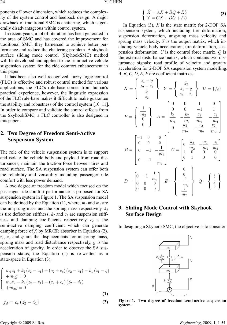 24 Y. CHEN Copyright © 2009 SciRes. Engineering, 2009, 1, 1-54 ponents of lower dimension, which reduces the complex- ity of the system control and feedback design. A major drawback of traditional SMC is chattering, which is gen- erally disadvantageous within control system. In recent years, a lot of literature has been generated in the area of SMC and has covered the improvement for traditional SMC, they harnessed to achieve better per- formance and reduce the chattering problem. A skyhook surface sliding mode control (SkyhookSMC) method will be developed and applied to the semi-active vehicle suspension system for the ride comfort enhancement in this paper. It has been also well recognized, fuzzy logic control (FLC) is effective and robust control method for various applications, the FLC’s rule-base comes from human's practical experience, however, the linguistic expression of the FLC rule-base makes it difficult to make guarantee the stability and robustness of the control system [10-11]. In order to compare and validate the control effects from the SkyhookSMC, a FLC controller is also designed in this paper. 2. Two Degree of Freedom Semi-Active Suspension System The role of the vehicle suspension system is to support and isolate the vehicle body and payload from road dis- turbances, maintain the traction force between tires and road surface. The SA suspension system can offer both the reliability and versatility including passenger ride comfort with less power demand. A two degree of freedom model which focused on the passenger ride comfort performance is proposed for SA suspension system in Figure 1. The SA suspension model can be defined by the Equation (1), where, m1 and m2 are the unsprung mass and the sprung mass respectively, k1 is tire deflection stiffness, k2 and c2 are suspension stiff- ness and damping coefficients respectively, ce is the semi-active damping coefficient which can generate damping force of fd by MR/ER absorber in Equation (2). z1, z2 and q are the displacements for unsprung mass, sprung mass and road disturbance respectively, g is the acceleration of gravity. In order to observe the SA sus- pension status, the Equation (1) is re-written as a state-space in Equation (3). (1) (2) (3) In Equation (3), X is the state matrix for 2-DOF SA suspension system, which including tire deformation, suspension deformation, unsprung mass velocity and sprung mass velocity. Y is the output matrix, which in- cluding vehicle body acceleration, tire deformation, sus- pension deformation. U is the control force matrix. Q is the external disturbance matrix, which contains two dis- turbance signals: road profile of velocity and gravity acceleration for 2-DOF SA suspension system modelling. A, B, C, D, E, F are coefficient matrixes. 3. Sliding Mode Control with Skyhook Surface Design In designing a SkyhookSMC, the objective is to consider Figure 1. Two degree of freedom semi-active suspension system.  Y. CHEN 25 Copyright © 2009 SciRes. Engineering, 2009, 1, 1-54 the non-linear tether system as the controlled plant, and therefore defined by the general state-space in Equation (4), where x ∈ Rn is the state vector, n is the order of the non-linear system, and u ∈ Rm is the input vector, m is the number of inputs. (4) s(e,t) is the sliding surface of the hyper-plane, which is given in Equation (5) and shown in Figure 2, where λ is a positive constant that defines the slope of the sliding surface. (5) In the 2-DOF SA suspension system, we let n = 2, given that, as it is a second-order system in which s de- fines the position and velocity errors. (6) From Equations (5) and (6), the second-order tracking problem is now being replaced by a first-order stabiliza- tion problem in which the scalar s is kept at zero by means of a governing condition [12]. This is obtained from use of the Lyapunov stability theorem, given in Equation (7), and it states that the origin is a globally asymptotically stable equilibrium point for the control system. Equation (7) is positive definite and its time de- rivative is given in inequality (8), to satisfy the negative definite condition, the system should satisfy the inequal- ity in (8). (7) (8) The ideal Skyhook control strategy was introduced in 1974 by Karnopp et al. [13], which is known as one of the most effective in terms of the simplicity of the con- trol algorithm. Figure 3 gives the ideal skyhook control scheme, the basic idea is to link the vehicle body sprung Figure 2. Sliding surface design. mass to the stationary sky by a controllable ‘skyhook’ damper, which could generate the controllable force of fskyhook and reduce the vertical vibrations by the road dis- turbance of all kinds [14-15]. Their original work uses only one inertia damper between the sprung mass and the inertia frame. The skyhook control is applicable for both a semi-active system as well as an active system. In practical, the skyhook control law was designed to modulate the damping force by a passive device to ap- proximate the force that would be generated by a damper fixed to an inertial reference as the ‘sky’. The skyhook control can reduce the resonant peak of the sprung mass quite significantly and thus can achieve a good ride quality. By borrowing this idea to reduce the sliding chattering phenomenon, in Figure 4, a soft switch- ing control law is introduced for the major sliding sur- face switching activity in Equation (9), which is to achieve good switch quality for the SkyhookSMC. The variable of s is defined in Equation (6), which contains the system information. It can be taken as a part of the SkyhookSMC control law in Equation (9), where c0 is an Figure 3. Ideal Skyhook control scheme. Figure 4. Sliding mode surface design with skyhook con- trol law.  26 Y. CHEN Copyright © 2009 SciRes. Engineering, 2009, 1, 1-54 assumed positive damping ratio for the switching control law. The SkyhookSMC needs to be chosen in such a way that the existence and the reachability of the slid- ing-mode are both guaranteed. Noting that δ is an as- sumed positive constant which defines the thickness of the sliding mode boundary layer [16]. (9) 4. Fuzzy Logic Controller Design Fuzzy logic control is a practical alternative for a vari- ety of challenging control applications, because it pro- vides a convenient method for constructing nonlinear controllers via the use of heuristic information. The fuzzy logic control’s rule-base comes from an operator’s experience that has acted as a human-in-the-loop con- troller. It actually provides a human experience based representing and implementing the ideas that human has about how to achieve high-performance control. The structure of the FLC for the 2-DOF SA suspen- sion system is shown in Fig. 5, the ‘If-Then’ rule-base is then applied to describe the experts' knowledge. Fig. 6 is the 2-in-1-out FLC rule-base cloud which can drive the FLC inference mechanism. The FLC rule-base is char- acterized by a set of linguistic description rules based on conceptual expertise which arises from typical human situational experience. The 2-in-1-out FLC rule-base for Figure 5. 2-in-1-out fuzzy logic control workflow diagram. defines the relationship between 2 inputs of the error (E) and the change in error (EC) with 1 output of the semi-active control force (U). The full 2-in-1-out FLC rule-base is given in Table 1, which can map the FLC rule-base based on the inputs information of semi-active suspension body acceleration to the output control force. the ride comfort of the 2-DOF SA suspension system is given in Table 1, which came from previous experience gained for the semi-active damping force control during body acceleration changes for ride comfort. Briefly, the main linguistic control rules are: 1) when the body ac- celeration increases, the SA damping force increases; 2) Conversely, when the body acceleration decreases, the SA damping force decreases. Fuzzification is the process of decomposing the sys- tem inputs into the fuzzy sets, that is, it is to map vari- ables from practical space to fuzzy space. The process of fuzzification allows the system inputs and outputs to be expressed in linguistic terms so that rules can be applied Figure 6 is the a rule-base 3D cloud map plot, which Table 1. 2-in-1-out FLC rule table for 2-DOF SA suspension system. U EC NLNMNS ZE PS PMPL NL PLPLPM PS PS PSZE NM PLPM PS PS PS ZENS ENSPMPSZE ZE ZE NS NM ZE PMPSZE ZE ZE NSNM PS PMPSZE ZE ZE NSNM PM PSZEZE ZE ZE NMNL PL ZENSNS NS NM NLNL Figure 6. FLC rule-base 3D cloud map.  Y. CHEN 27 Copyright © 2009 SciRes. Engineering, 2009, 1, 1-54 in a simple manner to express a complex system. In the FLC for 2-DOF SA suspension system, there are 7 ele- ments in the fuzzy sets for 2 inputs of Error(E) and Er- ror-in-Change(EC) and 1 output of FL are: < NL, NM, NS, ZE, PS, PM, PL >, the Fuzzy Inference System (FIS) of Mamdani-type inference for the FLC is shown in Fig- ure 8. Defuzzification is the opposite process of fuzzifica- tion, it is to map variables from fuzzy space to practical space. Figure 7. 2-in-1-out FLC inference system. Basically, a membership function (MF) is a generali- zation of the indicator function in classical sets, which defines how each point in the input space is mapped to a membership value between 0 and 1. The MF for the 2-DOF SA suspension system is the triangular-shaped membership function, the MF for E is shown in Figure 8, the MF for EC and U are also triangular-shaped mem- bership function with same elements range. The inputs of E and EC are interpreted from this fuzzy set, and the degree of membership is interpreted. Figure 8. Tr iangular -shaped membership function for FLC controller. 5. Simulation and Conclusions In the simulation for the control on 2-DOF SA suspen- sion system, it is excited by a random road disturbance loading which is described by the road profile with the parameters of reference space frequency n0 and road roughness coefficient P(n 0) in Table 2. The numerical esults are obtained using a MATLAB/SIMULINK. The velocity and acceleration of vehicle body are selected as error (e) and change in error (ec) feedback signals for the 2-DOF SA suspension system control. Unless stated oth- erwise all the results are generated using the following parameters for SA suspension system and controller in Table 2. Generally and partly, there are three perform- ance indexes for vehicle suspension system, which in- clude body acceleration, suspension deformation and tire load. In this context, the three indexes are good enough to evaluate the performance of the 2-DOF SA suspension system. r Table 2. 2-DOF SA suspension parameters. m1 Unsprung mass, kg 36 m2 Sprung mass, kg 240 c2 Suspension damping coefficient, Ns/m 1400 k1 Tire stiffness coefficient, N/m 160000 k2 Suspension stiffness coefficient, N/m 16000 g Gravity acceleration, m/s2 9.81 Ke FLC scaling gains for e −1 Kec FLC scaling gains for ec −10 Ku FLC scaling gains for u 21 C0 SkyhookSMC damping coefficient −5000 δ Thickness of the sliding mode boundary layer 28.1569 λ Slope of the sliding surface 10.6341 n0 Reference space frequency, m−1 0.1 P (n0)Road roughness coefficient, m3/cycle 256 × 10−6 v0 Vehicle speed, km/h 72  28 Y. CHEN Copyright © 2009 SciRes. Engineering, 2009, 1, 1-54 Figure 9. MATLAB/SIMULINK block for 2-DOF SA suspension system. Figure 9 is the SkyhookSMC and FLC MAT- LAB/SIMULINK block for 2-DOF SA suspension sys- tem, which can compare the ride comfort performance with both SkyhookSMC and FLC control methods, all the post-simulation data analysis and plots are also gen- erated by this SIMULINK block and its support MAT- LAB functions. Mostly, a road profile is a series of random data in the actual surroundings. That is reason to describe the road profile by statistical techniques. One practical statistical way to generate road input is describing the road rough- ness in power spectral density (PSD). To generate the road profile of a random base excitation for the 2-DOF SA suspension simulation disturbance, a spectrum of the geometrical road profile with road class roughness-C is considered. The vehicle is travelling with a constant speed v0, the time histories data of road irregularity are described by PSD method [17-19]. According to Inter- national Standard Organization (ISO)2631 [20], the ride comfort is specified in terms of root mean square (RMS) acceleration over a frequency range, in this simulation the RMS values for SkyhookSMC and FLC are {1.0530, 1.3134}, respectively, which confirms the validation of the SkyhookSMC on the ride comfort enhancement for 2-DOF SA suspension system. The FLC parameters require a judicious choice of the scaling gains of {Ke, Kec} for fuzzification and the scal- ing gain of {Ku} for defuzzification, in which, the {Ku} is used to map the control force from the fuzzy space range to practical space range that actuators can work practi- cally. Similarly, the SkyhookSMC damping coefficient c0 is required to expand the normalised controller output force into a practical range. The thickness of the sliding mode boundary layer is given by δ = 28.1569, and the slope of the sliding surface λ = 10.6341. Both of δ and λ value came from previous passive 2-DOF SA suspension system simulation results without control. With different simulation results of SkyhookSMC and FLC for the 2-DOF SA suspension system, all the control methods have an effect on the ride comfort enhancement for the 2-DOF suspension system in the given initial conditions. Figure 10 gives the vertical behaviour of body accel- eration - ride comfort performance. The upper subplot in Fig. 10 contains the body acceleration plots for SA sus- pension with FLC and passive suspension system, the FLC has body acceleration reducing effects on the pas- sive suspension system to some extend, which depends on the human experience in FLC’s rule-base. Meanwhile, the lower subplot in Figure 10 compares the control ef- fects of SkyhookSMC and FLC control methods, it shows SkyhookSMC has better control effect than the FLC on body acceleration reducing.  Y. CHEN 29 C opyright © 2009 SciRes. Engineering, 2009, 1, 1-54 Figure 10. 2-DOF SA suspension system body acceleration response with SkyhookSMC vs. FLC control. Figure 11. 2-DOF SA suspension deformation response with SkyhookSMC vs. FLC control methods. Figure 11 shows the relative displacement between vehicle sprung mass and unsprung mass - suspension deformation, both of the plots in the simulation are showing the appearance of better and stable ride comfort. In Figure 11 the SkyhookSMC has also smaller suspen- sion deformation than the FLC and passive suspension system, which also provides better ride comfort per- formance. According to Figure 10 and Figure 11, Sky- hookSMC can provide better body acceleration and sus- pension deformation at the same time.  30 Y. CHEN Copyright © 2009 SciRes. Engineering, 2009, 1, 1-54 Figure 12 shows the tire load of the 2-DOF SA sus- pension system. In the upper subplot of Figure 12, when the FLC taking its effects on the SA system, the tire load staying in the same level as the passive suspension sys- tem. In the lower subplot of Figure 12, the tire load per- forms smaller and better when SkyhookSMC taking ef- fects on the 2-DOF SA suspension system than FLC act- ing on the 2-DOF SA suspension system. Figure 13 is the body acceleration amplitude in fre- quency domain, it shows that all the control methods of SkyhookSMC and FLC can reduce at two of the key resonance peak points (10 and 101 Hz). It also shows the SkyhookSMC has better control effects on 2-DOF SA suspension system ride comfort enhancement than tradi- tional FLC and passive suspension system, but in higher frequency range, FLC has better performance than the SkyhookSMC to some extent in higher frequency range (>101Hz). Figure 12. 2-DOF SA tire load response with SkyhookSMC vs. FLC control methods. Figure 13. 2-DOF SA suspension system body acceleration response in frequency domain.  Y. CHEN 31 Copyright © 2009 SciRes. Engineering, 2009, 1, 1-54 Figure 14. 2-DOF SA suspension system body response phase plot. Figure 15. Sliding surface switching plot. The phase plot (body velocity vs. body acceleration) is shown in Figure 14 as limit cycles with behaviour for 2-DOF SA suspension body vertical vibration, the curves started from the initial value point of (0,g), and gathered to the stable points area around (0,0) in close-wise direc- tion, clearly, SkyhookSMC controller goes faster from the start point to steady status point, which corroborated the 2-DOF SA suspension system’s SkyhookSMC con- trollable steady-state. 6. Future Work The further study on the FLC and SkyhookSMC control methods by experimental system for the 2-DOF SA sus- pension system need to be designed. The further control methods will be studied to balance the control ability of FLC and SkyhookSMC to make obvious enhancement for the 2-DOF SA suspension system ride comfort in both time and frequency domain.  32 Y. CHEN Copyright © 2009 SciRes. Engineering, 2009, 1, 1-54 The parameter settings for the FLC and SkyhookSMC, including the SkyhookSMC damping coefficient c0, thickness of the sliding mode boundary layer δ, slope of the sliding surface λ and FLC scaling gains of {Ke, Kec, Ku}, need further consideration because the current simulation results come from manual parameter selection which based on passive suspension system simulation results. In order to enhance the parameter selection proc- ess and validation, some computational intelligence (CI) optimisation tools, such as Genetic Algorithms (GA) and Artificial Neural Networks (ANN), could be applied for parameter selection for the FLC and SkyhookSMC, this can hopefully give some reference sets for parameter selection. A GA has been used as an optimisation tool for parameter selection of the motorised momentum ex- change tether system payload transfer from low Earth orbit to geostationary Earth orbit, and the GA’s optimisa- tion ability has therefore been reasonably demonstrated [21]. 7. Acknowledgements The author would like to acknowledge the support pro- vided by the Overseas Research Students Awards Scheme and the Scholarship awarded by the University of Glasgow’s Faculty of Engineering. 8. References [1] K. Yi, M. Wargelin, and K. Hedrick, “Dynamic tire force control by semiactive suspensions,” Journal of Dynamic Systems, Measurement, and Control, Vol. 115, No. 3, pp. 465-474, 1993. [2] N. Jalili, “A comparative study and analysis of semi-active vibration-control systems,” Journal of Vibra- tion and Acoustics, Vol. 124, No. 4, pp. 593-605, 2002. [3] R. Stanway, “The development of force actuators using ER and MR fluid technology,” Actuator Technology: Current Practice and New Developments, IEE Collo- quium on (Digest No: 1996/110), Vol. 6, pp. 1-5, 1996. [4] L. Caracoglia and N. P. Jones, “Passive hybrid technique for the vibration mitigation of systems of interconnected stays,” Journal of Sound and Vibration, Vol. 307, No. 3-5, pp. 849-864, 2007. [5] Q. Zhou, S. R. K. Nielsen, and W. L. Qu, “Semi-active control of shallow cables with magnetorheological dampers under harmonic axial support motion,” Journal of Sound and Vibration, Vol. 311, No. 3-5, pp. 683-706, 2008. [6] S. V. Emelyanov, “Variable structure control systems (in Russian),” Moscow: Nauka, 1967. [7] Y. Itkis, “Control systems of variable structure,” New York: Wiley, 1976. [8] V. A. Utkin, “Sliding modes and their application in vari- able structure systems,” Moscow: Nauka (in Russian), 1978. [9] J. Y. Hung, W. Gao, and J. C. Hung, “Variable structure control: A survey,” IEEE Transactions on Industrial Elec- tronics, pp. 2-22, 1993. [10] L. A. Zadeh, “Fuzzy sets,” Information and Control, Vol. 8, No. 3, pp. 338–353, 1965. [11] K. M. Passino and S. Yurkovich, “Fuzzy control,” Addi- son Wesley Longman, Menlo Park, CA, 1998. [12] J. J. E. Slotine and W. P. Li, “Applied nonlinear control,” Prentice-Hall International, 1991. [13] D. C. Karnopp, M. J. Crosby, and R. A. Harwood, “Vi- bration control using semi-active force generators,” Journals of Engineering for Industry, Transactions of the ASME, Vol. 94, pp. 619-626, 1974. [14] H.-S. Kima and P. N. Roschke, “Design of fuzzy logic controller for smart base isolation system using genetic algorithm,” Engineering Structures, Vol. 28, No. 1, pp. 84-96, 2006. [15] S. M. Savaresi, E. Silani, and S. Bittanti, “Accelera- tion-Driven-Damper (ADD): An optimal control algo- rithm for comfort-oriented semiactive suspensions,” ASME Transactions: Journal of Dynamic Systems, Measurement and Control, Vol. 127, No. 2, pp. 218-229, 2005. [16] J. J. E. Slotine, “Tracking control of non-linear systems using sliding surfaces with application to robot manipula- tions,” PhD Dissertation, Laboratory for Information and Decision Systems, Massachusetts Institute of Technology, 1982. [17] E. M. Elbeheiry and D. C. Karnopp, “Optimal control of vehicle random vibration with constrained suspension deflection,” Journal of Sound and Vibration, Vol. 189, No. 5, pp. 547-564, 1996. [18] Y. Liu, H. Matsuhisaa, and H. Utsunoa, “Semi-active vibration isolation system with variable stiffness and damping control,” Journal of Sound and Vibration, Vol. 313, No. 1-2, pp. 16-28, 2008. [19] K. Ramji, A. Gupta, V. H. Saran, V. K. Goel, and V. Kumar, “Road roughness measurements using PSD ap- proach,” Journal of the Institution of Engineers, Vol. 85, pp. 193-201, 2004. [20] International Organization for Standardization, “Me- chanical vibration and shock – evaluation of human ex- posure to whole-body vibration – Part 1: General re- quirements,” ISO 2631-1, 1997. [21] Y. Chen and M. P. Cartmell, “Multi-objective optimisa- tion on motorised momentum exchange tether for pay- load orbital transfer,” IEEE Congress on Evolutionary Computation, pp. 987-993, September 25-28, 2007. |