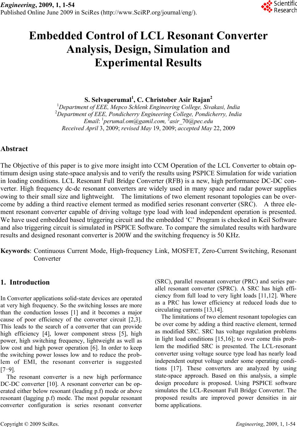
 Engineering, 2009, 1, 1-54 Published Online June 2009 in SciRes (http://www.SciRP.org/journal/eng/). Copyright © 2009 SciRes. Engineering, 2009, 1, 1-54 Embedded Control of LCL Resonant Converter Analysis, Design, Simulation and Experimental Results S. Selvaperumal1, C. Christober Asir Rajan2 1Department of EEE, Mepco Schlenk Engineering College, Sivakasi, India 2Department of EEE, Pondicherry Engineering College, Pondicherry, India Email: 1perumal.om@gamil.co m, 2asir_70@pec.edu Received April 3, 2009; revised May 19, 2009; accepted May 22, 2009 Abstract The Objective of this paper is to give more insight into CCM Operation of the LCL Converter to obtain op- timum design using state-space analysis and to verify the results using PSPICE Simulation for wide variation in loading conditions. LCL Resonant Full Bridge Converter (RFB) is a new, high performance DC-DC con- verter. High frequency dc-dc resonant converters are widely used in many space and radar power supplies owing to their small size and lightweight. The limitations of two element resonant topologies can be over- come by adding a third reactive element termed as modified series resonant converter (SRC). A three ele- ment resonant converter capable of driving voltage type load with load independent operation is presented. We have used embedded based triggering circuit and the embedded ‘C’ Program is checked in Keil Software and also triggering circuit is simulated in PSPICE Software. To compare the simulated results with hardware results and designed resonant converter is 200W and the switching frequency is 50 KHz. Keywords: Continuous Current Mode, High-frequency Link, MOSFET, Zero-Current Switching, Resonant Converter 1. Introduction In Converter applications solid-state devices are operated at very high frequency. So the switching losses are more than the conduction losses [1] and it becomes a major cause of poor efficiency of the converter circuit [2,3]. This leads to the search of a converter that can provide high efficiency [4], lower component stress [5], high power, high switching frequency, lightweight as well as low cost and high power operation [6]. In order to keep the switching power losses low and to reduce the prob- lem of EMI, the resonant converter is suggested [7-9]. The resonant converter is a new high performance DC-DC converter [10]. A resonant converter can be op- erated either below resonant (leading p.f) mode or above resonant (lagging p.f) mode. The most popular resonant converter configuration is series resonant converter (SRC), parallel resonant converter (PRC) and series par- allel resonant converter (SPRC). A SRC has high effi- ciency from full load to very light loads [11,12]. Where as a PRC has lower efficiency at reduced loads due to circulating currents [13,14]. The limitations of two element resonant topologies can be over come by adding a third reactive element, termed as modified SRC. SRC has voltage regulation problems in light load conditions [15,16]; to over come this prob- lem the modified SRC is presented. The LCL-resonant converter using voltage source type load has nearly load independent output voltage under some operating condi- tions [17]. These converters are analyzed by using state-space approach. Based on this analysis, a simple design procedure is proposed. Using PSPICE software simulates the LCL-Resonant Full Bridge Converter. The proposed results are improved power densities in air borne applications. 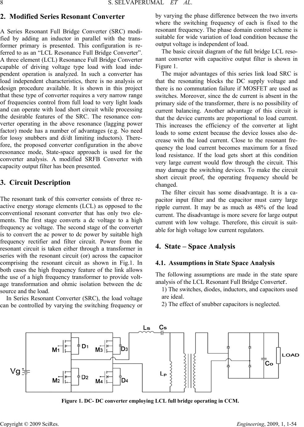 8 S. SELVAPERUMAL ET AL. Copyright © 2009 SciRes. Engineering, 2009, 1, 1-54 2. Modified Series Resonant Converter A Series Resonant Full Bridge Converter (SRC) modi- fied by adding an inductor in parallel with the trans- former primary is presented. This configuration is re- ferred to as an “LCL Resonance Full Bridge Converter”. A three element (LCL) Resonance Full Bridge Converter capable of driving voltage type load with load inde- pendent operation is analyzed. In such a converter has load independent characteristics, there is no analysis or design procedure available. It is shown in this project that these type of converter requires a very narrow range of frequencies control from full load to very light loads and can operate with load short circuit while processing the desirable features of the SRC. The resonance con- verter operating in the above resonance (lagging power factor) mode has a number of advantages (e.g. No need for lossy snubbers and di/dt limiting inductors). There- fore, the proposed converter configuration in the above resonance mode, State-space approach is used for the converter analysis. A modified SRFB Converter with capacity output filter has been presented. 3. Circuit Description The resonant tank of this converter consists of three re- active energy storage elements (LCL) as opposed to the conventional resonant converter that has only two ele- ments. The first stage converts a dc voltage to a high frequency ac voltage. The second stage of the converter is to convert the ac power to dc power by suitable high frequency rectifier and filter circuit. Power from the resonant circuit is taken either through a transformer in series with the resonant circuit (or) across the capacitor comprising the resonant circuit as shown in Fig.1. In both cases the high frequency feature of the link allows the use of a high frequency transformer to provide volt- age transformation and ohmic isolation between the dc source and the load. In Series Resonant Converter (SRC), the load voltage can be controlled by varying the switching frequency or by varying the phase difference between the two inverts where the switching frequency of each is fixed to the resonant frequency. The phase domain control scheme is suitable for wide variation of load condition because the output voltage is independent of load. The basic circuit diagram of the full bridge LCL reso- nant converter with capacitive output filter is shown in Figure 1. The major advantages of this series link load SRC is that the resonating blocks the DC supply voltage and there is no commutation failure if MOSFET are used as switches. Moreover, since the dc current is absent in the primary side of the transformer, there is no possibility of current balancing. Another advantage of this circuit is that the device currents are proportional to load current. This increases the efficiency of the converter at light loads to some extent because the device losses also de- crease with the load current. Close to the resonant fre- quency the load current becomes maximum for a fixed load resistance. If the load gets short at this condition very large current would flow through the circuit. This may damage the switching devices. To make the circuit short circuit proof, the operating frequency should be changed. The filter circuit has some disadvantage. It is a ca- pacitor input filter and the capacitor must carry large ripple current. It may be as much as 48% of the load current. The disadvantage is more severe for large output current with low voltage. Therefore, this circuit is suit- able for high voltage low current regulators. 4. State – Space Analysis 4.1. Assumptions in State Space Analysis The following assumptions are made in the state spare analysis of the LCL Resonant Full Bridge Converter. 1) The switches, diodes, inductors, and capacitors used are ideal. 2) The effect of snubber capacitors is neglected. Figure 1. DC- DC converter employing LCL full bridge operating in CCM. 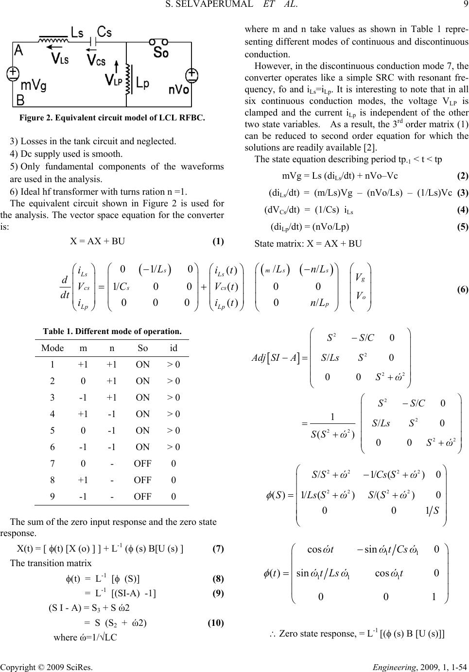 S. SELVAPERUMAL ET AL. 9 Copyright © 2009 SciRes. Engineering, 2009, 1, 1-54 Figure 2. Equivalent circuit model of LCL RFBC. 3) Losses in the tank circuit and neglected. 4) Dc supply used is smooth. 5) Only fundamental components of the waveforms are used in the analysis. 6) Ideal hf transformer with turns ration n =1. The equivalent circuit shown in Figure 2 is used for the analysis. The vector space equation for the converter is: X = AX + BU (1) where m and n take values as shown in Table 1 repre- senting different modes of continuous and discontinuous conduction. However, in the discontinuous conduction mode 7, the converter operates like a simple SRC with resonant fre- quency, fo and iLs=iLp. It is interesting to note that in all six continuous conduction modes, the voltage VLP is clamped and the current iLp is independent of the other two state variables. As a result, the 3rd order matrix (1) can be reduced to second order equation for which the solutions are readily available [2]. The state equation describing period tp-1 < t < tp mVg = Ls (diLs/dt) + nVo–Vc (2) (diLs/dt) = (m/Ls)Vg – (nVo/Ls) – (1/Ls)Vc (3) (dVCs/dt) = (1/Cs) iLs (4) (diLp/dt) = (nVo/Lp) (5) State matrix: X = AX + BU 01/ 0// () 1/00( )00 000() 0/ smss Ls Lsg cs scs o p Lp Lp LLn iit V dVC Vt dt V iit L nL (6) Table 1. Different mode of operation. Mode m n So id 1 +1 +1 ON > 0 2 0 +1 ON > 0 3 -1 +1 ON > 0 4 +1 -1 ON > 0 5 0 -1 ON > 0 6 -1 -1 ON > 0 7 0 - OFF 0 8 +1 - OFF 0 9 -1 - OFF 0 The sum of the zero input response and the zero state response. X(t) = [ (t) [X (o) ] ] + L-1 ( (s) B[U (s) ] (7) The transition matrix (t) = L-1 [ (S)] (8) = L-1 [(SI-A) -1] (9) (S I - A) = S3 + S ώ2 = S (S2 + ώ2) (10) where ώ=1/√LC 2 2 22 2 2 22 22 /0 /0 00 /0 1/0 () 00 SSC AdjSIAS LsS Sώ SSC SLs S SS ώ Sώ 22 22 22 22 /1/() ()1/ ()/()0 00 SS ώCs Sώ SLsSώSS ώ S 0 1 11 11 1 cos sin0 () sincos0 00 ώtώtCsώ tώtLsώώt 1 Zero state response, = L-1 [( (s) B [U (s)]]  10 S. SELVAPERUMAL ET AL. Copyright © 2009 SciRes. Engineering, 2009, 1, 1-54 22 22 122 22 11 11 1 ()/sin( /1/()0/// 1/()/()000[1c o s() ] 0010// /( ) p p p mVgnVo Zosώtt SS ώCs SώmLsnLsVgS LLsSώSS ώmVg nVoώtt SnLpVoS VoLp tt ) p x(t) = [ (t) [ x(o) ] + L-1 [ (s) B[U (s)] ] 1 1111111 111 11 1 cos()sin()/0 ()()/sin() () ()sin()/cos1( )0( )[1 () 001() ppLsp Ls cs cs ppp Lp Lp p ώtt tώttLsώittmVgnVo Zosώtt it Vt ώtt Csώώ ttVtt mVgnVo it itt 11 1 cos ()] /( ) p p ώtt nVoLp tt I Ls(t) = cos ώ1 (t-tp-1) ILs(tp-1) + (sin ώ 1(t-tp-1) / Ls ώ1) VCs(tp-1)+ ( ( mVg-nVo) / Zos) sin ώ1 (t-tp-1) (11) I Ls(t) = ILs ( tp-1 ) cos[ώ1(t - tp-1)] + [(mVg – nVo –Vcs (tp-1) / Zos ] sin[ώos(t - tp-1)] (12) Vcs(t) = iLs (tp-1) Zos sin [ώos ( t - tp-1)] + (m Vg - nVo) [1-cos ώ1(t-tp-1)] + Vcs (tp-1) cos [ώ1(t-tp-1)] (13) iLp (t) = iLp ( t p-1) + ( n / Lp ) Vo ( t - tp-1 ) (14) where, tp-1 is the time at the start of any, ccm. tp is the time at the end of the same ccm. Similarly, the solutions for the discontinuous conduction mode are: iLs = iLp. iLs(t) = iLp(t) = iLs ( tp-1 ) cos [ώo ( t – t p-1) ] + [(mVg-Vcs (tp-1) / Zo) sin( t - tp-1)] (1 5) VCs(t) = iLs (t p-1) Zo sin [ώo( t - tp-1)] + mVg[1-cos[ώo(t - tp-1)]] + Vcs(tp-1) cos (ώo (t -t p-1)] (16) where D is the duty cycle = / (Ts / 2) From Mo equation, it can be concluded that the output voltage is not dependent on the load resistance and con- verter gain follows a sine function. These results are completely validated experimentally by plotting the variation of Mo with duty ratio. At the optimum normal- ized switching frequency fno, mo is independent of varia- tions in the load resistance for all pulse widths. The de- viation increases with reducing values of load resistance or increasing values of load current for the given voltage. This arises because of sensing resistance of 0.5 used in series with the resonant element for monitoring its and also finite resistance offered by diodes and MOSFET’S in conduction. In order to maintain the output voltage constant at desired value against the variations in the load resistance and supply voltage variations, the pulse width has to be changed in a closed-loop manner. How- ever, the required change in pulse width to maintain con- stant output voltage against load variations and constant input voltage is very small. 5. Design Procedure 5.1. Design: (Operating Switching Frequency = 50khz) It is desired to design the converter with the following specifications: 1) Power output =200W 2) Minimum input voltage =100V 3) Minimum output voltage =125V 4) Maximum load current = 1.6 A 5) Maximum overload current = 4A 6) Inductance ratio (KL) = 1 The hf transformer turns ratio assumed to be unity. The load resistance: RL= Maximum output voltage / maximum output current. = 100 / 1.6 = 62.5 63 Figure 3. Variation of voltage gain with the duty ratio. 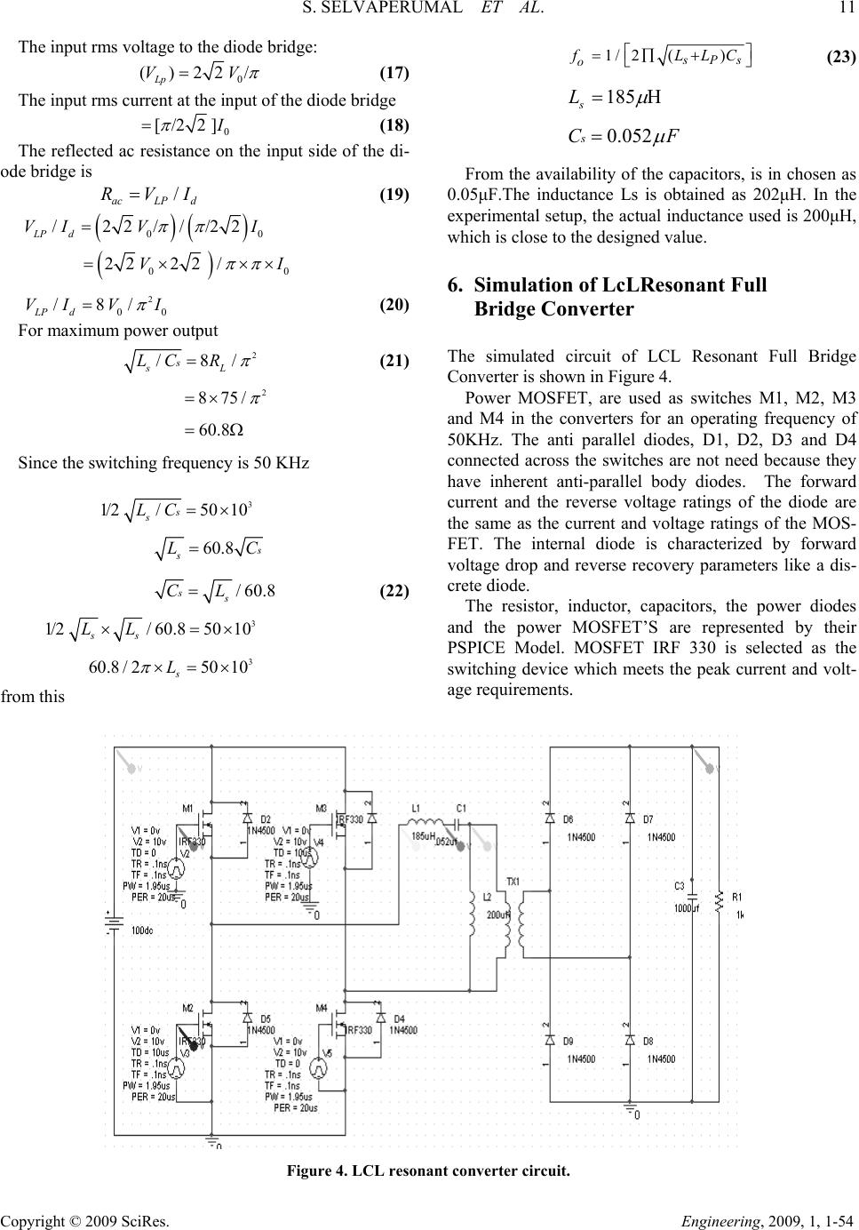 S. SELVAPERUMAL ET AL. 11 Copyright © 2009 SciRes. Engineering, 2009, 1, 1-54 The input rms voltage to the diode bridge: 0 ()22/ Lp VV (17) The input rms current at the input of the diode bridge 0 [/22] (18) The reflected ac resistance on the input side of the di- ode bridge is / acLP d VI (19) 00 / 22///22 LP d VI VI 00 2222 /VI 0 2 0 /8/ LP d VIV I (20) For maximum power output 2 /8/s sL LC R (21) 2 875/ 60.8 Since the switching frequency is 50 KHz 3 1/2/5010s s LC 60.8 s LC /60.8ss CL (22) 3 1/2/ 60.85010 ss LL 3 60.8 /25010 s L from this 1/ 2() Ps o LLC (23) 185 s L 0.052sCF From the availability of the capacitors, is in chosen as 0.05μF.The inductance Ls is obtained as 202μH. In the experimental setup, the actual inductance used is 200μH, which is close to the designed value. 6. Simulation of LcLResonant Full Bridge Converter The simulated circuit of LCL Resonant Full Bridge Converter is shown in Figure 4. Power MOSFET, are used as switches M1, M2, M3 and M4 in the converters for an operating frequency of 50KHz. The anti parallel diodes, D1, D2, D3 and D4 connected across the switches are not need because they have inherent anti-parallel body diodes. The forward current and the reverse voltage ratings of the diode are the same as the current and voltage ratings of the MOS- FET. The internal diode is characterized by forward voltage drop and reverse recovery parameters like a dis- crete diode. The resistor, inductor, capacitors, the power diodes and the power MOSFET’S are represented by their PSPICE Model. MOSFET IRF 330 is selected as the switching device which meets the peak current and volt- age requirements. Figure 4. LCL resonant converter circuit. 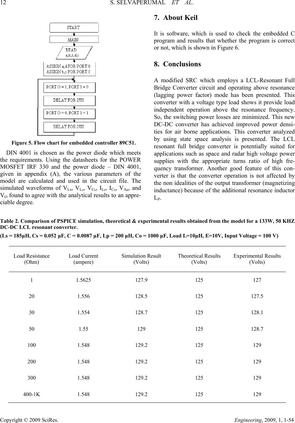 12 S. SELVAPERUMAL ET AL. Copyright © 2009 SciRes. Engineering, 2009, 1, 1-54 Figure 5. Flow chart for embedded controller 89C51. DIN 4001 is chosen as the power diode which meets the requirements. Using the datasheets for the POWER MOSFET IRF 330 and the power diode – DIN 4001, given in appendix (A), the various parameters of the model are calculated and used in the circuit file. The simulated waveforms of VLs, VLP, VCS, ILP, ICS, VAB, and VO found to agree with the analytical results to an appre- ciable degree. 7. About Keil It is software, which is used to check the embedded C program and results that whether the program is correct or not, which is shown in Figure 6. 8. Conclusions A modified SRC which employs a LCL-Resonant Full Bridge Converter circuit and operating above resonance (lagging power factor) mode has been presented. This converter with a voltage type load shows it provide load independent operation above the resonance frequency. So, the switching power losses are minimized. This new DC-DC converter has achieved improved power densi- ties for air borne applications. This converter analyzed by using state space analysis is presented. The LCL resonant full bridge converter is potentially suited for applications such as space and radar high voltage power supplies with the appropriate turns ratio of high fre- quency transformer. Another good feature of this con- verter is that the converter operation is not affected by the non idealities of the output transformer (magnetizing inductance) because of the additional resonance inductor LP. Table 2. Comparison of PSPICE simulation, theoretical & experimental results obtained from the model for a 133W, 50 KHZ DC-DC LCL resonant converter. (Ls = 185μH, Cs = 0.052 μF, C = 0.0087 μF, Lp = 200 μH, Co = 1000 μF, Load L=10μH, E=10V, Input Voltage = 100 V) Load Resistance (Ohm) Load Current (ampere) Simulation Result (Volts) Theoretical Results (Volts) Experimental Results (Volts) 1 1.5625 127.9 125 127 20 1.556 128.5 125 127.5 30 1.554 128.7 125 128.1 50 1.55 129 125 128.7 100 1.548 129.2 125 129 200 1.548 129.2 125 129 300 1.548 129.2 125 129 400-1K 1.548 129.2 125 129 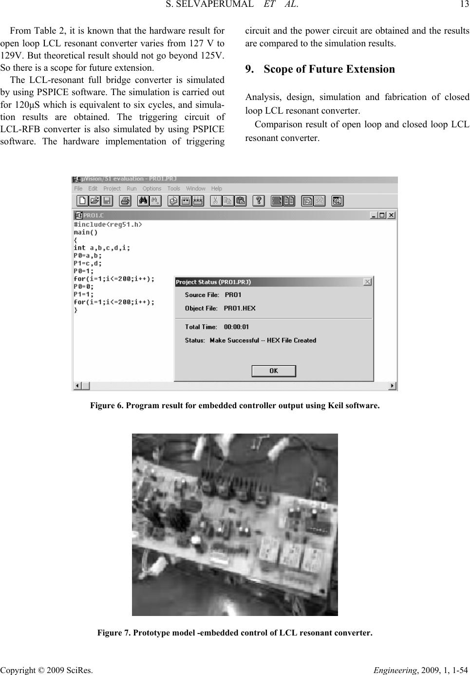 S. SELVAPERUMAL ET AL. 13 Copyright © 2009 SciRes. Engineering, 2009, 1, 1-54 From Table 2, it is known that the hardware result for open loop LCL resonant converter varies from 127 V to 129V. But theoretical result should not go beyond 125V. So there is a scope for future extension. The LCL-resonant full bridge converter is simulated by using PSPICE software. The simulation is carried out for 120μS which is equivalent to six cycles, and simula- tion results are obtained. The triggering circuit of LCL-RFB converter is also simulated by using PSPICE software. The hardware implementation of triggering circuit and the power circuit are obtained and the results are compared to the simulation results. 9. Scope of Future Extension Analysis, design, simulation and fabrication of closed loop LCL resonant converter. Comparison result of open loop and closed loop LCL resonant converter. Figure 6. Program result for embedded controller output using Keil software. Figure 7. Prototype model -embedded control of LCL resonant converter. 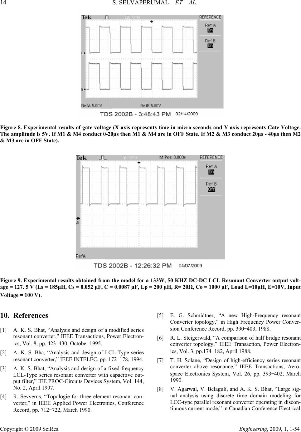 14 S. SELVAPERUMAL ET AL. Copyright © 2009 SciRes. Engineering, 2009, 1, 1-54 Figure 8. Experimental results of gate voltage (X axis represents time in micro seconds and Y axis represents Gate Voltage. The amplitude is 5V. If M1 & M4 conduct 0-20µs then M1 & M4 are in OFF State. If M2 & M3 conduct 20µs - 40µs then M2 & M3 are in OFF State). Figure 9. Experimental results obtained from the model for a 133W, 50 KHZ DC-DC LCL Resonant Converter output volt- age = 127. 5 V (Ls = 185μH, Cs = 0.052 μF, C = 0.0087 μF, Lp = 200 μH, R= 20Ω, Co = 1000 μF, Load L=10μH, E=10V, Input Voltage = 100 V). 10. References [1] A. K. S. Bhat, “Analysis and design of a modified series resonant converter,” IEEE Transactions, Power Electron- ics, Vol. 8, pp. 423-430, October 1995. [2] A. K. S. Bha, “Analysis and design of LCL-Type series resonant converter,” IEEE INTELEC, pp. 172-178, 1994. [3] A. K. S. Bhat, “Analysis and design of a fixed-frequency LCL-Type series resonant converter with capacitive out- put filter,” IEE PROC-Circuits Devices System, Vol. 144, No. 2, April 1997. [4] R. Sevverns, “Topologie for three element resonant con- verter,” in IEEE Applied Power Electronics, Conference Record, pp. 712-722, March 1990. [5] E. G. Schmidtner, “A new High-Frequency resonant Converter topology,” in High Frequency Power Conver- sion Conference Record, pp. 390-403, 1988. [6] R. L. Steigerwald, “A comparison of half bridge resonant converter topology,” IEEE Transaction, Power Electron- ics, Vol. 3, pp.174-182, April 1988. [7] T. H. Solane, “Design of high-efficiency series resonant converter above resonance,” IEEE Transactions, Aero- space Electronics System, Vol. 26, pp. 393-402, March 1990. [8] V. Agarwal, V. Belaguli, and A. K. S. Bhat, “Large sig- nal analysis using discrete time domain modeling for LCC-type parallel resonant converter operating in discon- tinuous current mode,” in Canadian Conference Electrical  S. SELVAPERUMAL ET AL. 15 Copyright © 2009 SciRes. Engineering, 2009, 1, 1-54 and Computer Engineering, pp. 83–88, 1993. [9] K. S Bhat, “Analysis and design of a series parallel reso- nant converter,” IEEE Transactions on Power Electronics, Vol. 8, pp.1–11, 1993. [10] V. Belaguli, “Series-parallel and parallel series resonant converters operating on the utility line-analysis, simula- tion and experimental results,” Ph.D. Dissertation, Uni- versity Victoria, 1995. [11] R. Severns, “Topologies for three element resonant con- verters,” in IEEE Applied Power Electronics, Conference Record, pp. 712–722, 1990. [12] H. Neufeld, “Half-bridge resonant converter using the CS-360,” Cherry Semiconductor, Application Note, 1990. [13] B. P. McGrath, “Design of a soft-switched 6-kw battery charger for traction applications,” IEEE Transactions on Power Electronics, Vol. 22, No. 4, pp.1136–1142, July 2007. [14] H. Deng, “Analysis and design of iterative learning con- trol strategies for UPS inverters,” IEEE Transactions on Industrial Electronics, Vol. 54, No. 3, pp. 1739–1751, June 2007. [15] F. Z. Peng, “Z-Source inverter for motor drives,” IEEE Transactions on Power Electronics, Vol. 20, No. 4, pp.857–862, July 2005. [16] V. Belaguli, “Series-parallel and resonant converter oper- ating in DCM–Analysis, design, simulation and experi- mental results,” IEEE Transactions on Circuits and Sys- tems, Vol. 47, pp. 433–441, 2000. [17] Y. Jang, “Isolated boost converters,” IEEE Transactions on Power Electronics, Vol. 22, No. 4, pp. 1514–1521, July 2007.
|