 Journal of Computer and Communications, 2014, 2, 43-50 Published Online March 2014 in SciRes. http://www.scirp.org/journal/jcc http://dx.doi.org/10.4236/jcc.2014.24007 How to cite this paper: Jung, D.-J. and Lee, H.-K. (2014) Detection of the Single Image from DIBR Based on 3D Warping Trace and Edge Matching. Journal of Computer and Communications, 2, 43-50. http://dx.doi.org/10.4236/jcc.2014.24007 Detection of the Single Image from DIBR Based on 3D Warping Trace and Edge Matching Dae-Jin Jung, Heung-Kyu Lee* Department of Computer Science, Korea Advanced Institute of Science and Technology (KAIST), Daejeon, South Korea Email: djjung@mmc.kaist.ac.kr, *hklee@mmc.kaist.ac.kr Received October 2013 Abstract Recently, the popularity of 3D content is on the rise because of its immersive experience to view- ers. While demands for 3D contents and 3D technologies increase, only a few copyright protection methods for 3D contents have been proposed. The simplest infringement is the illegal distribution of the single 2D image from 3D content. The leaked image is still valuable as 2D content and the leakage can be occurred in DIBR system. To detect the leaked image, we focus on the hole-filled region which is caused by the hole-filling procedure mandatory in DIBR system. To estimate the hole-filled regions, two different procedures are conducted to extract edges and to estimate 3D warping traces, respectively. After that, the hole-filled regions are estimated and the left-right-eye image discrimination (LR discrimination) is also conducted. Experimental results demonstrate the effectiveness of the proposed method using quantitative measures. Keywords 3D; Stereoscopic Image; DIBR; Depth-Image-Based Rendering; Digital Forensics 1. Introduction As digital contents have been developed, the popularity of 3D content is on the rise because it provides an im- mersive experience to viewers by showing each slightly different image to each human eye. The demands for 3D content have been increased rapidly since the representative 3D film Avata had been released and the devel- opment in the 3D display accelerates the opportunity to experience 3D contents. While the 3D contents are de- veloped rapidly, only a few copyright protection methods for 3D contents have been proposed. The simplest copyright infringement in 3D contents is the illegal distribution of the single 2D image leaked from 3D contents. This infringement is feasible because the 2D image itself is still valuable as a 2D content. In this paper, we propose a method to detect the single image leaked from the 3D content. Specifically, we focus on detecting the single image leaked from depth-image-based rendering (DIBR) which is the representa- tive 3D content format. The images, which are generated by DIBR that utilizes both the center image and the *  D.-J. Jung, H.-K. Lee depth image, should have holes inside. Because the holes make viewers bother watching the 3D contents, hole- filling algorithm is conducted to cover the holes. As a result, the hole-filled regions leave trails by the operations of the hole-filling process. We focus on the hole-filled regions to detect the single image from DIBR. The char- acteristics of the hole-filled region are analyzed and utilized to detect the hole-filed regions. Even more, we classify the given image as the left-eye image or right-eye image. By exploiting that, we can help other method to protect 3D content copyright including watermarking detection. The rest of this paper is structured as follow. Section 2 introduces the background and related works. In Sec- tion 3, our proposed method is described in detail. After that, experimental results are exhibited in Section 4 and Section 5. 2. Background and Related Works 3D depth can be perceived by binocular disparity. To introduce the 3D depth perception for human, 3D contents contains two slightly different images for left and right human eyes. Because 3D contents have two images, dif- ferent formats compared to the formats of traditional 2D image are used to store the 3D contents. 3D contents are usually stored (or produced) in two representative formats. One, which is called stereo image rendering (SIR), is to store left and right images which are simultaneously taken for a scene. This method provides the high quality view because of two fine views for both left and right eyes. However, the recording process for the fine quality requires high costs to set the configurations of two different cameras such as same height, brightness and the tone of color. Furthermore, the depth configuration is fixed and the bandwidth for the transmission is doubled compared to the traditional TV broadcast system. Another representative 3D content format is DIBR. This format stores the center image and the gray-level depth map for the same scene. Both left and right images are created from the 3D warping process which re- quires the center image and the corresponding depth map as inputs. The DIBR provides several advantages compared to SIR. It requires less transmission bandwidth because of the highly compress-able depth map and the individualized depth configuration which can be provided by adjusting the depth map. Also, the center view of the DIBR-format provides the backward-compatibility to the traditional 2D TV broadcasting system. Figure 1 depicts the process of the DIBR. Once the center image and the gray-level depth are given, the 3D horizontal warping process is conducted. It warps pixels in the center image to the horizontal shifted points in the newly generated left and right images. The basic warping process is described below [1]: , (1) Here, and are the -coordinates after the 3D warping process from the original coordinate of the center image and is the baseline distance. is the relative depth calculated by ( ) near farfar 255 d Z ZZZ = −+ (2) where and are the depth value of front side and backside of the screen. is the depth value of the corresponding to the pixel of the center image. The range of the depth value is from 0 to 255. Low depth values indicate that the corresponding pixel is far from the viewers and high depth values indicate that the correspond- ing pixel is close to the viewers. After the 3D warping process is conducted, holes appear in the newly generated left and right images. The hole is a group of the pixels where none of the center image pixels is warped because of the occluded parts. To fill these holes, various hole-filling algorithms were proposed: constant color hole-filling [2], horizontal inter- polation hole-filling [3], in-painting hole-filling, extrapolation hole-filling [4], and mode selection [5]. While various 3D image techniques have been developed, only several 3D image forensics techniques, which protect the copyright and the integrity of 3D digital contents, have been proposed. Reference [6] proposed a method to detect the non-stereoscopic to stereoscopic splicing forgery by exploiting that non-stereoscopic image has no depth information. Reference [7] proposed a method to identify source 3D camera from SIR images by utilizing minimum average correlation filter to synthesize the photo-response non-uniformity estimated from left-eye and right-eye images. Reference [8] proposed a method to detect resampling factor of 3D images for DIBR by exploiting the resample factors of center and depth images are same. Reference [9] proposed a method 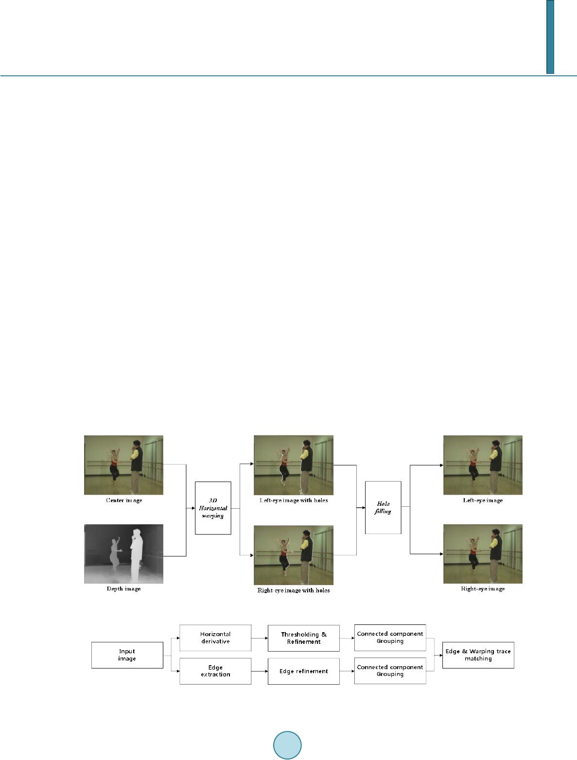 D.-J. Jung, H.-K. Lee to detect the single image leaked from DIBR system by analyzing horizontal neighboring pixels. This method and our proposed method have the same goal to achieve. Thus, we compare the test results of two schemes in the experimental results section. 3. Proposed Method Figure 2 depicts the overall process of the proposed method. The upper line shows the process of extracting 3D warping traces and the lower line shows the process of the edge extraction. The reasons why the proposed me- thod is split into two processes below: 1) Depth map is dependent on the objects of the center image. As shown in Figure 1, the depth map is correlated to the object of the corresponding center image. Most holes appear when a certain object is horizontally shifted by the wide interval and the neighboring objects (including backgrounds) were horizontally shifted by the narrow interval. It makes the holes appear horizontally adjacent to the edges of the objects. Therefore, the false positive detection ratio of the 3D warping traces can be reduced using the relation of the edges and the 3D warping traces. 2) The direction of the horizontal shift depends on the destination image. As shown in Equation (1), the horizontal shifting direction of an object depends on the destination image. For example, if the destination image is left-eye (right-eye) image, the objects in the center image is shifted to the right (left) direction. By exploiting it, the given image is determined whether it is the left-eye image or the right- eye image. The 3D warping traces and the edge groups are estimated from a suspicious image. Then, by matching them, the warping traces which are related to the edges are detected as the hole-filled regions. Also, the given image can be determined whether it is the left-eye image or the right-eye image. The details of the proposed method are explained as follow subsections. 3.1. Edge Extraction Procedure 3.1.1. Edge Extraction First, a given image is converted into a gray-scale image. To detect the edges, 2 different horizontal first deriva- tive filters were used. Figure 3(b) shows the result of edges extracted from Figure 3(a) by adopting the Figure 1. DIBR procedure. Figure 2. Overall process of the proposed method. 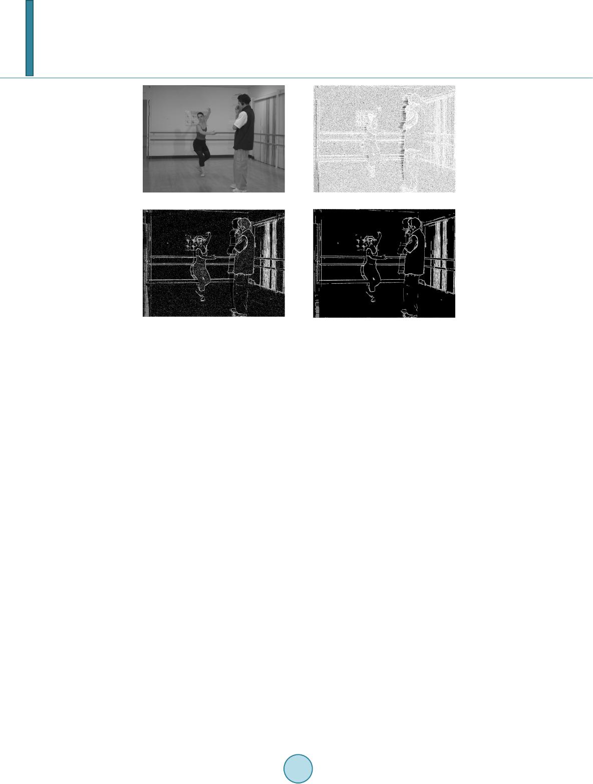 D.-J. Jung, H.-K. Lee (a) (b) (c) (d) Figure 3. Image results for edge extraction process. (a) Left-eye image from DIBR; (b) Edges extracted; (c) Edge thresholding; (d) Edge refinement. first derivative filters. Brighter regions are the edges in the figures. Then, thresholding is conducted for binariza- tion. Figure 3(c) shows the result of the binarization. 3.1.2. Edge Refinement In this step, the estimated edges are refined. The false positive edges and the edges which would not belong to the shifted objects are removed. The areas of the objects in the center image are broad and it makes the area of the edges from the objects be broader than those of other simple edges. To small edges, the estimated edges are grouped using 8-way connected components. If the size of a group is smaller than a certain threshold, it is re- moved. The threshold is set as 15 empirically. Figure 3(d) shows the result of the edge refinement. The refined edges are regrouped using 8-way connected components. By matching edge groups and the 3D warping traces, the hole-filled regions are estimated and the clue for the LR discrimination is provided. 3.2. 3D Warping Trace Estimation 3.2.1. Horizontal Derivative To detect the 3D warping trace, the hole-filled regions analysis is preceded. As explained in Section 2, the gen- erated images from DIBR contain the hole-filled regions. Most hole-filling algorithms utilize the horizontal in- terpolation due to the characteristics that the objects in the center image are shifted in the horizontal direction. Thus, pixels in the hole-filled regions are correlated with horizontal neighboring pixels. To detect the horizontal correlation, second derivative filter is used. 000 1 21 000 f h = − (3) Equation (3) describes the derivative filter used in the proposed method. It only handles its own horizontal directions. Figure 4(b) shows the result of the horizontal filtering of Figure 3(a). 3.2.2. Thresholding & Refinement Figure 4(a) presents the ground truth hole-filled regions. As Figu res 4(a) and (b) show, the most parts 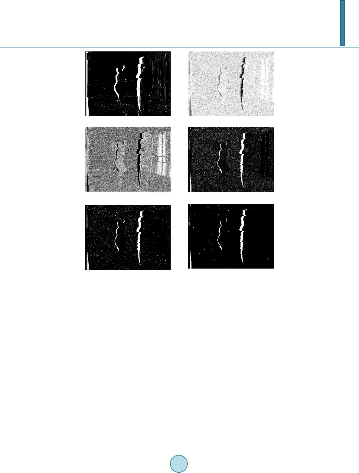 D.-J. Jung, H.-K. Lee (a) (b) (c) (d) Figure 4. Image results for 3D warping trace estimation process. (a) Holes in left-eye image; (b) Horizontal derivative filtering; (c) Thresholding; (d) Dilation & complement; (e) Median filtering; (f) Small area removal. of the hole-filled regions are dark in the result of the horizontal derivative filtering. However, excepting hole- filled regions, numerous dark spots appear due to the plain image parts and sensor noises including shot noise, shutter noise, and so on. Thresholding should be conducted to filter those parts. We set a relatively low value (3) as a threshold empirically to lower both the false positive detection and the computational complexity of the matching between extracted edges and warping traces. Figure 4(c) presents the result of the thresholding. It still has false positive regions. To minimize the false positive regions, various image processing are taken. Because the holes usually contain the continuous and wide area of pixels, small and discrete regions are excluded. Dila- tion, median filtering, and small area removal using 8-way connected component are conducted sequentially to obtain the warping traces. Then, they are regrouped using 8-way connected components for the matching with extracted edges. Figures 4(d)-(f) present the results of the above operations. 3.3. Edge & Warping Trace Matching In this step, the estimated 3D warping traces are matched to the extracted edges. If a warping trace is in close horizontal distance, which is set as 3, to a certain edge a matching is created. Only the pixels positioned in the same rows are compared for checking the horizontal distance. Before the matching procedure is conducted, the edge pixels of the warping traces are extracted to reduce the time complexity for comparing every possible pair. When a matching is created, the horizontal direction is also checked, then, the count for its direction is increased  D.-J. Jung, H.-K. Lee by the region size of the warping trace. After the matching, the warping traces which are not matched to the edges are removed and the given image is classified as the left-eye image or the right-eye image based on the direction counts. Figure 5(a) shows the result of the matching processes. At last, additional hole-filled region, which are irrelevant with the edges of the objects, are recovered. Those regions are created when the depth values of left-most and right-most areas of the depth image are bigger than zero. They are not related to the edges because the background is shifted. Thus, the warping traces removed by the matching process are checked if they are positioned in the side areas of the given image. Each left and right recovery region is set as a rectangle with 15% of the image width and the same height of the given image. Only the pixels are positioned in the recovery region. Figure 5(b) shows the result of additional hole-filled region re- covery. 4. Experimental Res ults In the experiments, two stereoscopic sequences from Ballet and Breakdancers are provided by Microsoft Re- search [10]. 8 cameras which are located in different spots captured the same scene and corresponding 8 depth sequences are provided. Each camera recorded 100 image sequences and 100 depth image sequences. The left-eye and the right-eye image sequences, which were totally 8 × 100 × 2 × 2 = 3200 images, were generated using mode selection technique [5]. To calculate the test results, ground truth hole-filled regions were checked while 3D warping and hole-filling are conducted. The proposed method and the comparison method of the ref- erence [9] are implemented in MATLAB 2012b. For quantitative tests, the precision for each camera is calculated. The reason why precision is used as a quan- titative measure instead of recall is that it is important to reduce false positive for practical works. The precision is described as follow: Detedted _ regionRelevant _ region precision Detected _ region ∩ = (4) where, the relevant region means the ground truth hole-filled region. Figures 6(a) and (b) presents the averaged precision of the Ballet sequences and Figures 6(c) and (d) shows the results from the Breakdancers sequences. As shown in Figure 6, the proposed method outperforms the reference [9]. The reference [9] showed the low precision in the sequences from Ballet because of the vertical blind in the right side of the image. On the con- trary, those regions are removed by low threshold and the matching process in the proposed method. In the LR discrimination, 234 images of total 3200 were classified into wrong directions, that is, the proposed method showed 92.69% detection ratio. The details of the detection results are described in Table 1. The reason why breakdancer showed low detection ratio is that the object, which has a large depth value difference with other objects, has the similar color of background on the right side. It caused the miss in the edge extraction and then, the large hole-filled region was not matched to the corresponding edges. For the precise test for distinguishing the images generated by DIBR from ordinary 2D images, 1600 center images were tested by both proposed method and reference [9]. Figure 7 presents the ROC curve for the test result. The proposed method showed good performance to detect the images from DIBR system. Our method showed better true positive ratio than that of reference [9] at the same level of false positive ratio. (a) (b) Figure 5. Image results for edge-3D warping trace matching process. (a) E dge-3D warping trace matching; (b) Additional hole-filled region recovery. 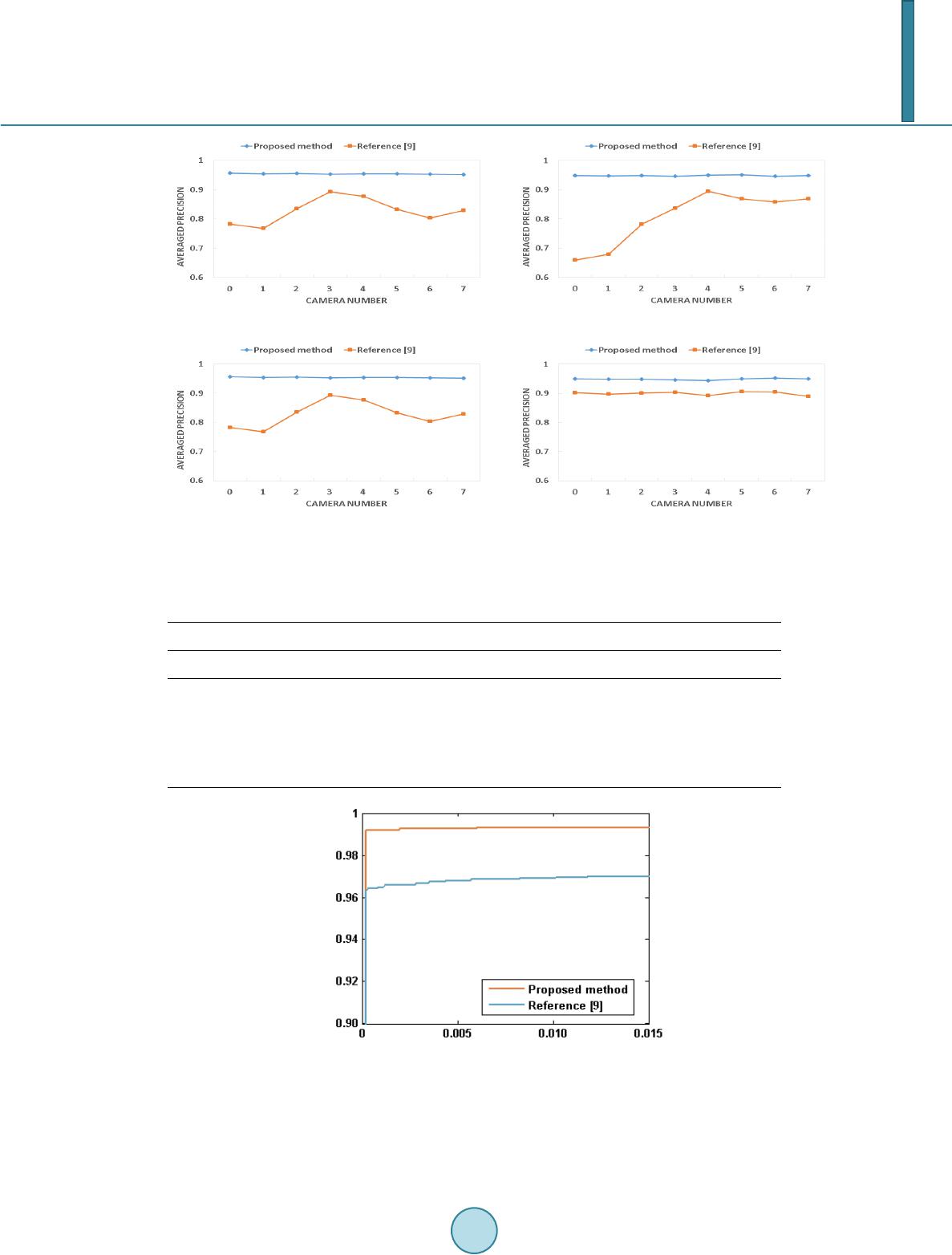 D.-J. Jung, H.-K. Lee (a) (b) (c) (d) Figure 6. Averaged precision from image sequences. (a) Ballet left-eye image sequence; (b) Ballet right-eye im- age sequence; (c) Breakdancer left-eye image sequence; (d) Breakdancer right-eye image sequence. Table 1. LR discrimination result. Camera number 0 1 2 3 4 5 6 7 Ballet L 100 100 100 100 100 100 100 100 R 100 100 100 100 100 100 100 100 Breakdancer L 135 136 124 119 135 120 137 128 R 65 64 76 81 65 80 63 72 Figure 7. ROC curve. 5. Conclusion In this paper, we proposed the method to detect the single image from DIBR. The images generated by DIBR have hole-filled regions which are caused by 3D warping using the depth map. Those regions are horizontally  D.-J. Jung, H.-K. Lee correlated and adjacent to corresponding edges. We extracted edges and horizontally correlated 3D warping traces. As a result, the hole-filled regions are estimated by matching the edges and warping traces. Experimental results showed that our proposed method performed good at both distinguishing DIBR generated images and LR discrimination by quantitative measures. For future works, various hole-filling algorithms will be tested and the further study for suppressing error rate of the source direction identification will be conducted. Acknowledgements This work was supported by the National Research Foundation of Korea (NRF) grant funded by the Korea gov- ernment (MEST) (No. 2012R1A2A1A05026327). References [1] Lin, Y.H. and Wu, J.L. (2005) A Digital Blind Watermarking for Depth-Image-Based Rendering 3D Images. IEEE Transactions on Broadcasting, 57, 602-611. http://dx.doi.org/10.1109/TBC.2011.2131470 [2] Vazquez, C., Tam, W.J. and Speranza, F. (2006) Stereoscopic Imaging: Filling Disoccluded Areas in Depth Image- Based Rendering. SPIE, 6392. [3] Bertalmio, M., Sapiro, G., Caselles, V. and Ballester, C. (2000) Image Inpainting. Proceedings of ACM SIGGRAPH, New Orleans, July 2000, 417-4 24. [4] Po, L.M., Zhang, S., Xu, X. and Zhu, Y. (2011) A New Multidirectional Extrapolation Hole-Filling Method for Depth- Image-Based Rendering. 18th IEEE International Conference on Image Processing (ICIP 2011), Brussels, 11-14 Sep- tember 2011, 2589-2592, [5] De Silva, D.V.S.X. , Fernando, W.A.C. and Arachchi, H.K. (2010) A New Mode Selection Technique for Coding Depth Maps of 3D Video. IEEE International Conference on Acoustics Speech and Signal Processing (ICASSP), Dal- las, 14-19 March 2010, 686-689. [6] Fouche, M. and Olivier, M. S. (2011) Detecting Non-Stereoscopic to Stereoscopic Image Splicing with the Use of Dis- parity Maps. Proceedings of the South African Institute of Computer Scientists and Information Technologists Confer- ence on Knowledge, Innovation and Leadership in a Diverse, Multidisciplinary Environment, October 2011, 271-274. [7] Lee, J.H. , Hyun, D.K., Jung, D. J . and Lee, H. K. (2012) Source 3D Camera Identification Based on Synthesized PRNU. International Conference on 3D Systems and Applications (3DSA’2012), Hsinchu, 25 June 2012, 444 -448. [8] Choi, H.Y., Hyun, D. K. and Lee, H.K. (2012) Enhanced Resampling Detection for DIBR Stereoscopic Image. Interna- tional Conference on 3D Systems and Applications (3DSA’2012), Hsinchu, 25 June 2012, 506-510. [9] Choi, C.H. and Lee, H.K. (2012) Detection of the Single Image Leaked from DIBR System Based on the Horizontal Neighboring Pixels. International Conference on 3D Systems and Applications (3DSA’2012), Hsinchu, 25 June 2012, 506-510. [10] Zitnick, C.L ., Kang, S.B., Uyttendaele, M., Winder, S. and Szeliski, R. (2004) Hi gh -Quality Video View Interpolation Using a Layered Representation. Proceedings of ACM SIGGRAPH and ACM Transactions on Graphics, 2004, 600- 608.
|