 Materials Sciences and Applicatio ns, 2011, 2, 258-264 doi:10.4236/msa.2011.24033 Published Online April 2011 (http://www.scirp.org/journal/msa) Copyright © 2011 SciRes. MSA NiOx Nanoparticle Synthesis by Chemical Vapor Deposition from Nickel Acetylacetonate Pavel Moravec1, Jiří Smolík1, Helmi Keskinen2,3, Jyrki M. Mäkelä2, Snejana Bakardjieva4, Valeri V. Levdansky5 1Institute of Chemical Process Fundamentals AS CR, Prague, Czech Republic; 2Department of Physics, Tampere University of Technology, Tampere, Finland; 3Department of Physics and Mathematics, University of Eastern Finland, Kuopio, Finland; 4Institute of Inorganic Chemistry AS CR, Husinec-Řež, Czech Republic; 5A. V. Luikov Heat and Mass Transfer Institute, National Academy of Sciences of Belarus, Minsk, Belarus Email: moravec@icpf.cas.cz, helmi.keskinen@uef.fi Received November 4th, 2010; revised January 17th, 2011; accepted March 9th, 2011. ABSTRACT Ni/NiO nanoparticles were synthesized by metal organics chemical vapor deposition of nickel acetylacetonate in an externally heated tube flow reactor at moderate temperatures, up to 500˚C. Particle production and characteristics were studied by evaluating the effects of reactor temp erature, precursor concentratio n, and flow rate through the reac- tor. In addition, two precursor decomposition methods were examined: thermal decomposition and reduction by hy- drogen. Particle production was monitored with a scanning mobility particle sizer, and particle characteristics were studied using transmission electron microscopy, high resolution transmission electron microscopy, selected area elec- tron diffraction, and energy dispersive spectroscopy. The presence of hydrogen in the reaction mixture influenced sig- nificantly both particle production and their characteristics. Keywords: Nickel Nanostructures, MOCVD, Hot Wall Tube Reactor, Electron Diffraction 1. Introduction Nickel and nickel oxide nanoparticles show many unique optical, magnetic, electrical and chemical properties [1,2], and thus, these nanoparticles have great potential in ap- plications such as ceramic materials, electronic compo- nents, sensors, magnetic data storage materials and cata- lysts [3,4]. However, most physical and chemical proper- ties depend on the size and shape of the nanoparticles [5]. Moreover, nickel nanoparticles are unstable in air, and their surface can oxidize to NiO even at room tempera- ture [6]. In recent years, several methods of Ni/NiO nanopartic- le synthesis have been reported and, of course, each dif- ferent method of synthesis imparts the final product with different properties. Liquid phase synthesis is one subset of methods for synthesizing Ni/NiO [7-9], but wet chem- istry methods can be quite expensive, particularly in the steps that involve solid-liquid separation, washing and drying [10]. Ni/NiO nanoparticles also can be synthesized in the gas phase, and several variants of this method have been used for the preparation of nickel or nickel oxide nano- particles. In one case, Ni/NiO particles were synthesized by spray pyrolysis of water solutions of nickel precursors (e.g., nitrate, chloride, formate or acetate) but the result- ing particles typically were in the submicron size range [11] or were polydisperse mixtures of nanosized particles, submicron-sized particles and, under some conditions, even supermicron-sized particles [12]. However, Leng- goro et al. [3] developed conditions for synthesizing NiO nanoparticles with controlled morphology by using low-pressure spray pyrolysis with a filter expansion aero- sol generator [3]. Nickel nanoparticles also have been synthesized by a DC sputtering process in an argon at- mosphere [13] or by a laser-assisted photonucleation process [1]. Suh et al. synthesized nickel nanoparticles in a tubular furnace reactor reducing NiCl2 with hydrogen (present in a carrier gas) [2]. Another method for prepar- ing Ni/NiO nanostructures is chemical vapor deposition (CVD) of metal organic precursors (MOCVD). MOCVD has a number of advantages over other methods: the process is relatively simple, it uses inexpensive equip- ment, and particle formation can be controlled by a vari- ety of process parameters like reactor temperature, pre- 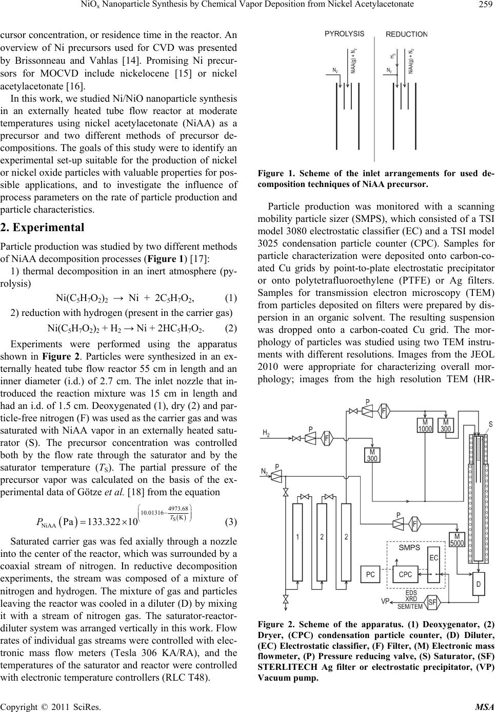 NiO Nanoparticle Synthesis by Chemical Vapor Deposition from Nickel Acetylacetonate 259 x cursor concentration, or residence time in the reactor. An overview of Ni precursors used for CVD was presented by Brissonneau and Vahlas [14]. Promising Ni precur- sors for MOCVD include nickelocene [15] or nickel acetylacetonate [16]. In this work, we studied Ni/NiO nanoparticle synthesis in an externally heated tube flow reactor at moderate temperatures using nickel acetylacetonate (NiAA) as a precursor and two different methods of precursor de- compositions. The goals of this study were to identify an experimental set-up suitable for the production of nickel or nickel oxide particles with valuable properties for pos- sible applications, and to investigate the influence of process parameters on the rate of particle production and particle characteristics. 2. Experimental Particle production was studied by two different methods of NiAA decomposition processes (Figure 1) [17]: 1) thermal decomposition in an inert atmosphere (py- rolysis) Ni(C5H7O2)2 → Ni + 2C5H7O2, (1) 2) reduction with hydrogen (present in the carrier gas) Ni(C5H7O2)2 + H2 → Ni + 2HC5H7O2. (2) Experiments were performed using the apparatus shown in Figure 2. Particles were synthesized in an ex- ternally heated tube flow reactor 55 cm in length and an inner diameter (i.d.) of 2.7 cm. The inlet nozzle that in- troduced the reaction mixture was 15 cm in length and had an i.d. of 1.5 cm. Deoxygenated (1), dry (2) and par- ticle-free nitrogen (F) was used as the carrier gas and was saturated with NiAA vapor in an externally heated satu- rator (S). The precursor concentration was controlled both by the flow rate through the saturator and by the saturator temperature (TS). The partial pressure of the precursor vapor was calculated on the basis of the ex- perimental data of Götze et al. [18] from the equation S 4973.68 10.01316 K NiAA Pa133.322 10 T P (3) Saturated carrier gas was fed axially through a nozzle into the center of the reactor, which was surrounded by a coaxial stream of nitrogen. In reductive decomposition experiments, the stream was composed of a mixture of nitrogen and hydrogen. The mixture of gas and particles leaving the reactor was cooled in a diluter (D) by mixing it with a stream of nitrogen gas. The saturator-reactor- diluter system was arranged vertically in this work. Flow rates of individual gas streams were controlled with elec- tronic mass flow meters (Tesla 306 KA/RA), and the temperatures of the saturator and reactor were controlled with electronic temperature controllers (RLC T48). Figure 1. Scheme of the inlet arrangements for used de- composition techniques of NiAA precursor. Particle production was monitored with a scanning mobility particle sizer (SMPS), which consisted of a TSI model 3080 electrostatic classifier (EC) and a TSI model 3025 condensation particle counter (CPC). Samples for particle characterization were deposited onto carbon-co- ated Cu grids by point-to-plate electrostatic precipitator or onto polytetrafluoroethylene (PTFE) or Ag filters. Samples for transmission electron microscopy (TEM) from particles deposited on filters were prepared by dis- persion in an organic solvent. The resulting suspension was dropped onto a carbon-coated Cu grid. The mor- phology of particles was studied using two TEM instru- ments with different resolutions. Images from the JEOL 2010 were appropriate for characterizing overall mor- phology; images from the high resolution TEM (HR- Figure 2. Scheme of the apparatus. (1) Deoxygenator, (2) Dryer, (CPC) condensation particle counter, (D) Diluter, (EC) Electrostatic classifier, (F) Filter, (M) Electronic mass flowmeter, (P) Pressure reducing valve, (S) Saturator, (SF) STERLITECH Ag filter or electrostatic precipitator, (VP) Vacuum pump. C opyright © 2011 SciRes. MSA  NiO Nanoparticle Synthesis by Chemical Vapor Deposition from Nickel Acetylacetonate 260 x TEM) JEOL 3010 could also distinguish details on the particle surface. The crystallinity of the particles was studied by selected area electron diffraction (SAED) and by analysis of lattice fringes detected on particles. The composition of the particles was analyzed by energy dis- persive spectroscopy (EDS; Noran Vantage connected to JEOL 2010 and/or INCA/Oxford connected to JEOL 3010). Particle production and particle characteristics were also studied by varying reactor temperature (TR) (400˚C - 500˚C; the upper limit is set by the construction material of the reactor and furnace), reactor flow rate (QR, 400 - 1000 cm3/min), hydrogen concentration (cH, 0 vol% - 10 vol%), saturator temperature (TS, 150˚C - 190˚C), and central nozzle flow rate (QCF, 10% - 20% of QR). It should be noted that QCF and TS control the precursor concentration (PNiAA). Axial temperature profile in the reactor for TR set to 500˚C and QR = 0 is shown in Fig- ure 3. Experimental conditions for sample preparation are summarized in Table 1. 3. Results 3.1. Particle Production Particle generation was monitored by SMPS in the form of particle size distribution (PSD) curves, including the following statistics: total number concentration (Nt), geometric mean diameter (GMD), geometric standard deviation (GSD), etc. Several examples of PSD curves are shown in Figure 4 and Figure 5. dN/dlogdP repre- sents differential number concentration, normalized to one decade of particle size. The influence of reactor temperature on particle production was studied for re- ductive decomposition of NiAA. Particle generation was observed at temperatures of 400˚C and higher. No parti- cles were detected at TR = 300˚C. For thermal decompo- sition, experiments were performed only at TR = 500˚C. Figure 3. Axial temperature profile in the axis of the reactor for TR set to 500˚C. Table 1. Process parameters of the samples for particle characterization. Sample No. TR [˚C] TS [˚C] QR [cm3/min] PNiAA [Pa] cH [vol%] Rem. NiAA4 500180900 2.9 0 PYROLYSIS NiAA7 400180800 2.9 10 REDUCTION NiAA8 500180800 2.9 7 REDUCTION NiAA9 500180600 2.9 7 REDUCTION NiAA10500180800 2.9 10 REDUCTION NiAAF1500150800 0.48 0 PYROLYSIS NiAAF2500180800 2.9 0 PYROLYSIS Figure 4. Influence of TS on PSD at TR = 500˚C, QR = 800 cm3/min, QCF = 20% QR, pyrolysis. Generally, particle production (mean particle size and number concentration) increases with increasing satura- tor temperature (TS) (Figure 4). The particle concentra- tion increased from 4.92 × 106 cm–3 at TS = 150˚C to 2.85 × 107 cm–3 at 180˚C. Values of GMD at these TS values were 32 and 156 nm, respectively, and the GSD values were 1.37 and 1.52, respectively. Figure 5 shows the Figure 5. Particle size distributions corresponding to TEM samples NiAA4, NiAA7 and NiAA8. Experimental condi- tions are shown in Table 1. C opyright © 2011 SciRes. MSA  NiO Nanoparticle Synthesis by Chemical Vapor Deposition from Nickel Acetylacetonate 261 x influences of the precursor decomposition method and the reactor temperature; the remaining conditions in these experiments were nearly identical (Table 1). It is evident that the rate of particle formation by reduction of NiAA at 400˚C (NiAA7) is much lower (Nt = 7.48 × 106 cm−3, GMD = 26 nm, GSD = 1.38) than that at 500˚C (NiAA8, Nt = 2.96 × 107 cm−3, GMD = 59 nm, GSD = 1.58). At 500˚C, the mean particle size for reductive precursor decomposition (NiAA8) was smaller than those for thermal decomposition (NiAA4, Nt = 2.58 × 107 cm−3, GMD = 185 nm, GSD = 1.51) (Figure 5). The other pa- rameters in Table 1, i.e. reactor flow rate and/or hydro- gen concentration variation from 7 to 10 vol%, had not remarkable effect on particle production. 3.2. Particle Characteristics 3.2.1. Pyrolysis The morphology of particles prepared by pyrolysis of NiAA can be seen in Figure 6. The particles have shell-like structures, the mean size of the primary parti- cles is well below 50 nm and they are arranged into clus- ters and/or chains. The samples (NiAAF1, NiAAF2) de- posited on PTFE filter are dark in color, suggesting that they may be contaminated by carbon from incomplete decomposition of the precursor. Formation of carbon- coated Ni nanoparticles by thermal decomposition of solid nickel acetate in a closed Swagelok reactor was observed by Pol et al. [19]. Electron diffraction pattern Figure 6. Bright field TEM image and SAED pattern of particles prepared by pyrolysis of NiAA, sample NiAA4: TR = 500˚C, TS = 180˚C, QR = 900 cm3/min. (EDP) in Figure 6 is due to small particle size rather weak. Nevertheless, there are two recognizable rings in the EDP that correspond to interplanar spacings of 0.205 nm and 0.189 nm, respectively. There are also less-visi- ble dots that correspond to spacings of 0.176 nm, 0.123 nm and 0.106 nm. These values may represent d111 = 0.203 nm, d200 = 0.176 nm, d220 = 0.125 nm, d311 = 0.106 nm of face centred cubic (FCC) Ni (PDF ICDD 4-0850). The spacing 0.205 nm is also consistent with d200 = 0.208 nm FCC NiO (4-0835) and 0.123 nm is consistent with d311 = 0.126 or d222 = 0.121 nm of FCC NiO, but there are missing rings or dots corresponding to d111 and d220 NiO. The spacing 0.189 nm does not fit with any inter- planar spacing of either FCC Ni or FCC NiO. HRTEM images enabled a more detailed analysis of particle mor- phology, crystallinity and, therefore, particle composition. Figure 7 shows HRTEM images of particles of sample NiAAF1. We can see lattice fringes d111 of FCC Ni (4-0850), see area A and corresponding fast Fourier transformation (FFT) pattern in Figure 7(a) and d105 of hexagonal NiOOH (6-0075) (see area B and correspond- ing FFT in Figure 7(a). The crystalline structure of hex- agonal NiOOH (6-0075) and FCC NiO (22-1189) can be seen in Figure 7(b). As inset, there is FFT pattern of cubic NiO crystalline structure along [–300]c zone axis. EDS analysis (INCA Oxford) was applied to the samples NiAAF1 and NiAAF2, deposited on filters. The diameter of the spot area varied from ~5 nm to ~30 nm, and O/Ni (atomic%) ratios of 0.38 to 1.86 were obtained. Because the sensitivity of EDS to individual elements of the peri- odic table depends on the atomic number, the values of the O/Ni ratio do not reflect stoichiometry. Furthermore, the O/Ni ratio could be affected (increased) during the preparation of TEM samples from the particles deposited on filters. 3.2.2. Reduction of NiAA The morphology of particles obtained by reduction dif- fers significantly from those produced by thermal de- composition and depends also on the reactor temperature. At TR = 400˚C, primary particles 10 - 15 nm in size were agglomerated into clusters and/or chains, and they had Figure 7. HRTEM images and FFT patterns of particles prepared by pyrolysis of NiAA, sample NiAAF1: TR = 500˚C, TS = 150˚C, QR = 800 cm3/min. C opyright © 2011 SciRes. MSA 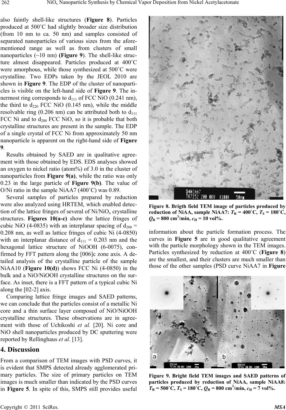 NiO Nanoparticle Synthesis by Chemical Vapor Deposition from Nickel Acetylacetonate 262 x also faintly shell-like structures (Figure 8). Particles produced at 500˚C had slightly broader size distribution (from 10 nm to ca. 50 nm) and samples consisted of separated nanoparticles of various sizes from the afore- mentioned range as well as from clusters of small nanoparticles (~10 nm) (Figure 9). The shell-like struc- ture almost disappeared. Particles produced at 400˚C were amorphous, while those synthesized at 500˚C were crystalline. Two EDPs taken by the JEOL 2010 are shown in Figure 9. The EDP of the cluster of nanoparti- cles is visible on the left-hand side of Figure 9. The in- nermost ring corresponds to d111 of FCC NiO (0.241 nm), the third to d220 FCC NiO (0.145 nm), while the middle resolvable ring (0.206 nm) can be attributed both to d111 FCC Ni and to d200 FCC NiO, so it is probable that both crystalline structures are present in the sample. The EDP of a single crystal of FCC Ni from approximately 50 nm nanoparticle is apparent on the right-hand side of Figure 9. Results obtained by SAED are in qualitative agree- ment with those obtained by EDS. EDS analyses showed an oxygen to nickel ratio (atom%) of 3.0 in the cluster of nanoparticles from Figure 9(a), while the ratio was only 0.23 in the large particle of Figure 9(b). The value of O/Ni ratio in the sample NiAA7 (400˚C) was 0.89. Several samples of particles prepared by reduction were also analyzed using HRTEM, which enabled detec- tion of the lattice fringes of several of Ni/NiOx crystalline structures. Figures 10(a-c) show the lattice fringes of cubic NiO (4-0835) with an interplanar spacing of d200 = 0.208 nm, as well as lattice fringes of cubic Ni (4-0850) with an interplanar distance of d111 = 0.203 nm and the hexagonal lattice structure of NiOOH (6-0075), con- firmed by FFT pattern along the [006]c zone axis. A de- tailed analysis of the crystalline particle of the sample NiAA10 (Figure 10(d)) shows FCC Ni (4-0850) in the bulk and a NiO/NiOOH crystalline structures on the sur- face. As inset, there is a FFT pattern of a typical cubic Ni along the [02-2] axis. Comparing lattice fringe images and SAED patterns, we can conclude that the particles consist of a metallic Ni core and a thin surface layer composed of NiO/NiOOH crystalline structures. These observations are in agree- ment with those of Uchikoshi et al. [20]. Ni core and NiO shell nanoparticles produced by DC sputtering were reported by Rellinghaus et al. [13]. 4. Discussion From a comparison of TEM images with PSD curves, it is evident that SMPS detected already agglomerated pri- mary particles. The size of primary particles on TEM images is much smaller than indicated by the PSD curves in Figure 5. In spite of this, SMPS still provides useful Figure 8. Brigth field TEM image of particles produced by reduction of NiAA, sample NiAA7: TR = 400˚C, TS = 180˚C, QR = 800 cm3/min, cH = 10 vol%. information about the particle formation process. The curves in Figure 5 are in good qualitative agreement with the particle morphology shown in the TEM images. Particles synthesized by reduction at 400˚C (Figure 8) are the smallest, and their clusters are much smaller than those of the other samples (PSD curve NiAA7 in Figure Figure 9. Bright field TEM images and SAED patterns of particles produced by reduction of NiAA, sample NiAA8: TR = 500˚C, TS = 180˚C, QR = 800 cm3/min, cH = 7 vol%. C opyright © 2011 SciRes. MSA 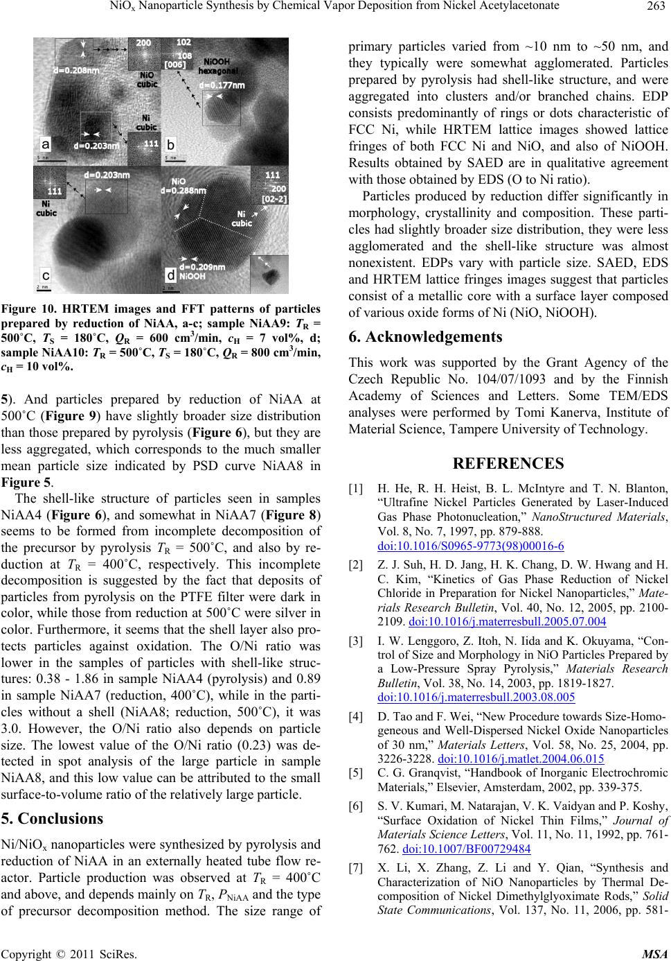 NiO Nanoparticle Synthesis by Chemical Vapor Deposition from Nickel Acetylacetonate 263 x Figure 10. HRTEM images and FFT patterns of particles prepared by reduction of NiAA, a-c; sample NiAA9: TR = 500˚C, TS = 180˚C, QR = 600 cm3/min, cH = 7 vol%, d; sample NiAA10: TR = 500˚C, TS = 180˚C, QR = 800 cm3/min, cH = 10 vol%. 5). And particles prepared by reduction of NiAA at 500˚C (Figure 9) have slightly broader size distribution than those prepared by pyrolysis (Figure 6), but they are less aggregated, which corresponds to the much smaller mean particle size indicated by PSD curve NiAA8 in Figure 5. The shell-like structure of particles seen in samples NiAA4 (Figure 6), and somewhat in NiAA7 (Figure 8) seems to be formed from incomplete decomposition of the precursor by pyrolysis TR = 500˚C, and also by re- duction at TR = 400˚C, respectively. This incomplete decomposition is suggested by the fact that deposits of particles from pyrolysis on the PTFE filter were dark in color, while those from reduction at 500˚C were silver in color. Furthermore, it seems that the shell layer also pro- tects particles against oxidation. The O/Ni ratio was lower in the samples of particles with shell-like struc- tures: 0.38 - 1.86 in sample NiAA4 (pyrolysis) and 0.89 in sample NiAA7 (reduction, 400˚C), while in the parti- cles without a shell (NiAA8; reduction, 500˚C), it was 3.0. However, the O/Ni ratio also depends on particle size. The lowest value of the O/Ni ratio (0.23) was de- tected in spot analysis of the large particle in sample NiAA8, and this low value can be attributed to the small surface-to-volume ratio of the relatively large particle. 5. Conclusions Ni/NiOx nanoparticles were synthesized by pyrolysis and reduction of NiAA in an externally heated tube flow re- actor. Particle production was observed at TR = 400˚C and above, and depends mainly on TR, PNiAA and the type of precursor decomposition method. The size range of primary particles varied from ~10 nm to ~50 nm, and they typically were somewhat agglomerated. Particles prepared by pyrolysis had shell-like structure, and were aggregated into clusters and/or branched chains. EDP consists predominantly of rings or dots characteristic of FCC Ni, while HRTEM lattice images showed lattice fringes of both FCC Ni and NiO, and also of NiOOH. Results obtained by SAED are in qualitative agreement with those obtained by EDS (O to Ni ratio). Particles produced by reduction differ significantly in morphology, crystallinity and composition. These parti- cles had slightly broader size distribution, they were less agglomerated and the shell-like structure was almost nonexistent. EDPs vary with particle size. SAED, EDS and HRTEM lattice fringes images suggest that particles consist of a metallic core with a surface layer composed of various oxide forms of Ni (NiO, NiOOH). 6. Acknowledgements This work was supported by the Grant Agency of the Czech Republic No. 104/07/1093 and by the Finnish Academy of Sciences and Letters. Some TEM/EDS analyses were performed by Tomi Kanerva, Institute of Material Science, Tampere University of Technology. REFERENCES [1] H. He, R. H. Heist, B. L. McIntyre and T. N. Blanton, “Ultrafine Nickel Particles Generated by Laser-Induced Gas Phase Photonucleation,” NanoStructured Materials, Vol. 8, No. 7, 1997, pp. 879-888. doi:10.1016/S0965-9773(98)00016-6 [2] Z. J. Suh, H. D. Jang, H. K. Chang, D. W. Hwang and H. C. Kim, “Kinetics of Gas Phase Reduction of Nickel Chloride in Preparation for Nickel Nanoparticles,” Mate- rials Research Bulletin, Vol. 40, No. 12, 2005, pp. 2100- 2109. doi:10.1016/j.materresbull.2005.07.004 [3] I. W. Lenggoro, Z. Itoh, N. Iida and K. Okuyama, “Con- trol of Size and Morphology in NiO Particles Prepared by a Low-Pressure Spray Pyrolysis,” Materials Research Bulletin, Vol. 38, No. 14, 2003, pp. 1819-1827. doi:10.1016/j.materresbull.2003.08.005 [4] D. Tao and F. Wei, “New Procedure towards Size-Homo- geneous and Well-Dispersed Nickel Oxide Nanoparticles of 30 nm,” Materials Letters, Vol. 58, No. 25, 2004, pp. 3226-3228. doi:10.1016/j.matlet.2004.06.015 [5] C. G. Granqvist, “Handbook of Inorganic Electrochromic Materials,” Elsevier, Amsterdam, 2002, pp. 339-375. [6] S. V. Kumari, M. Natarajan, V. K. Vaidyan and P. Koshy, “Surface Oxidation of Nickel Thin Films,” Journal of Materials Science Letters, Vol. 11, No. 11, 1992, pp. 761- 762. doi:10.1007/BF00729484 [7] X. Li, X. Zhang, Z. Li and Y. Qian, “Synthesis and Characterization of NiO Nanoparticles by Thermal De- composition of Nickel Dimethylglyoximate Rods,” Solid State Communications, Vol. 137, No. 11, 2006, pp. 581- C opyright © 2011 SciRes. MSA 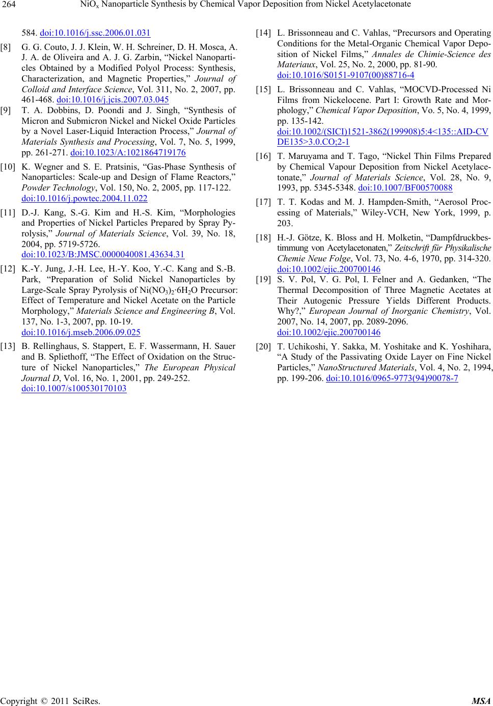 NiOx Nanoparticle Synthesis by Chemical Vapor Deposition from Nickel Acetylacetonate Copyright © 2011 SciRes. MSA 264 584. doi:10.1016/j.ssc.2006.01.031 [8] G. G. Couto, J. J. Klein, W. H. Schreiner, D. H. Mosca, A. J. A. de Oliveira and A. J. G. Zarbin, “Nickel Nanoparti- cles Obtained by a Modified Polyol Process: Synthesis, Characterization, and Magnetic Properties,” Journal of Colloid and Interface Science, Vol. 311, No. 2, 2007, pp. 461-468. doi:10.1016/j.jcis.2007.03.045 [9] T. A. Dobbins, D. Poondi and J. Singh, “Synthesis of Micron and Submicron Nickel and Nickel Oxide Particles by a Novel Laser-Liquid Interaction Process,” Journal of Materials Synthesis and Processing, Vol. 7, No. 5, 1999, pp. 261-271. doi:10.1023/A:1021864719176 [10] K. Wegner and S. E. Pratsinis, “Gas-Phase Synthesis of Nanoparticles: Scale-up and Design of Flame Reactors,” Powder Technology, Vol. 150, No. 2, 2005, pp. 117-122. doi:10.1016/j.powtec.2004.11.022 [11] D.-J. Kang, S.-G. Kim and H.-S. Kim, “Morphologies and Properties of Nickel Particles Prepared by Spray Py- rolysis,” Journal of Materials Science, Vol. 39, No. 18, 2004, pp. 5719-5726. doi:10.1023/B:JMSC.0000040081.43634.31 [12] K.-Y. Jung, J.-H. Lee, H.-Y. Koo, Y.-C. Kang and S.-B. Park, “Preparation of Solid Nickel Nanoparticles by Large-Scale Spray Pyrolysis of Ni(NO3)2·6H2O Precursor: Effect of Temperature and Nickel Acetate on the Particle Morphology,” Materials Science and Engineering B, Vol. 137, No. 1-3, 2007, pp. 10-19. doi:10.1016/j.mseb.2006.09.025 [13] B. Rellinghaus, S. Stappert, E. F. Wassermann, H. Sauer and B. Spliethoff, “The Effect of Oxidation on the Struc- ture of Nickel Nanoparticles,” The European Physical Journal D, Vol. 16, No. 1, 2001, pp. 249-252. doi:10.1007/s100530170103 [14] L. Brissonneau and C. Vahlas, “Precursors and Operating Conditions for the Metal-Organic Chemical Vapor Depo- sition of Nickel Films,” Annales de Chimie-Science des Materiaux, Vol. 25, No. 2, 2000, pp. 81-90. doi:10.1016/S0151-9107(00)88716-4 [15] L. Brissonneau and C. Vahlas, “MOCVD-Processed Ni Films from Nickelocene. Part I: Growth Rate and Mor- phology,” Chemical Vapor Deposition, Vo. 5, No. 4, 1999, pp. 135-142. doi:10.1002/(SICI)1521-3862(199908)5:4<135::AID-CV DE135>3.0.CO;2-1 [16] T. Maruyama and T. Tago, “Nickel Thin Films Prepared by Chemical Vapour Deposition from Nickel Acetylace- tonate,” Journal of Materials Science, Vol. 28, No. 9, 1993, pp. 5345-5348. doi:10.1007/BF00570088 [17] T. T. Kodas and M. J. Hampden-Smith, “Aerosol Proc- essing of Materials,” Wiley-VCH, New York, 1999, p. 203. [18] H.-J. Götze, K. Bloss and H. Molketin, “Dampfdruckbes- timmung von Acetylacetonaten,” Zeitschrift für Physikalische Chemie Neue Folge, Vol. 73, No. 4-6, 1970, pp. 314-320. doi:10.1002/ejic.200700146 [19] S. V. Pol, V. G. Pol, I. Felner and A. Gedanken, “The Thermal Decomposition of Three Magnetic Acetates at Their Autogenic Pressure Yields Different Products. Why?,” European Journal of Inorganic Chemistry, Vol. 2007, No. 14, 2007, pp. 2089-2096. doi:10.1002/ejic.200700146 [20] T. Uchikoshi, Y. Sakka, M. Yoshitake and K. Yoshihara, “A Study of the Passivating Oxide Layer on Fine Nickel Particles,” NanoStructured Materials, Vol. 4, No. 2, 1994, pp. 199-206. doi:10.1016/0965-9773(94)90078-7
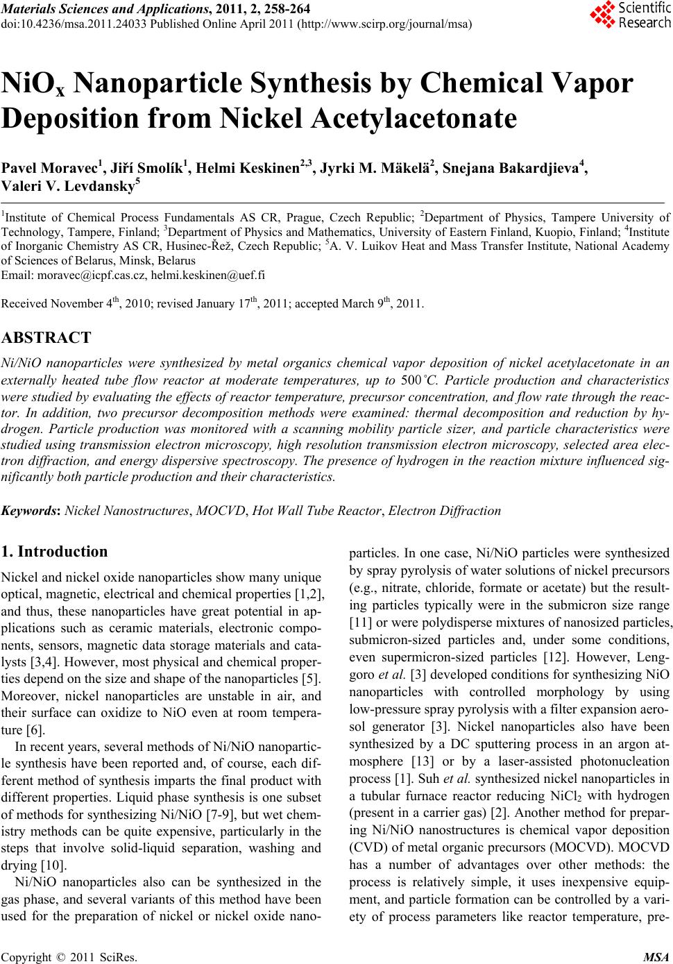
|