Paper Menu >>
Journal Menu >>
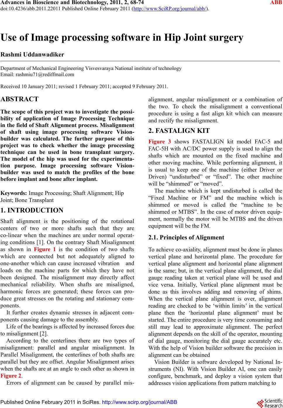 Advances in Bioscience and Biotechnology, 2011, 2, 68-74 ABB doi:10.4236/abb.2011.22011 Published Online February 2011 (http://www.SciRP.org/journal/abb/). Published Online February 2011 in SciRes. http://www.scirp.org/journal/ABB Use of Image processing software in Hip Joint surgery Rashmi Uddanwadiker Department of Mechanical Engineering Visvesvaraya National institute of technology Email: rashmiu71@rediffmail.com Received 10 January 2011; revised 1 February 2011; accepted 9 February 2011. ABSTRACT The scope of this project was to investigate the possi- bility of application of Image Processing Technique in the field of Shaft Alignment process. Misalignment of shaft using image processing software Vision- builder was calculated. The further purpose of this project was to check whether the image processing technique can be used in bone transplant surgery. The model of the hip was used for the experimenta- tion purpose. Image processing software Vision- builder was used to match the profiles of the bone before implant and bone after implant. Keywords: Image Processing; Shaft Alignment; Hip Joint; Bone Transplant 1. INTRODUCTION Shaft alignment is the positioning of the rotational centers of two or more shafts such that they are co-linear when the machines are under normal operat- ing conditions [1]. On the contrary Shaft Misalignment as shown in Figure 1 is the condition of two shafts which are connected but not adequately aligned to one-another which can cause increased vibration and loads on the machine parts for which they have not been designed. The misalignment may directly affect mechanical reliability. When shafts are misaligned, harmonic forces are generated; these forces can pro- duce great stresses on the rotating and stationary com- ponents. It further creates dynamic stresses in adjacent com- ponents causing damage to the assembly. Life of the bearings is affected by increased forces due to misalignment [2]. According to the centerlines there are two types of misalignment: parallel and angular misalignment. In Parallel Misalignment, the centerlines of both shafts are parallel but they are offset. Angular Misalignment arises when the shafts are at an angle to each other as shown in Figure 2. Errors of alignment can be caused by parallel mis- alignment, angular misalignment or a combination of the two. To check the misalignment a conventional procedure is using a fast align kit which can measure and rectify the misalignment. 2. FASTALIGN KIT Figure 3 shows FASTALIGN kit model FAC-5 and FAC-5H with AC/DC power supply is used to align the shafts which are mounted on the fixed machine and other moving machine. While performing alignment, it is usual to keep one of the machine (either Driver or Driven) “undisturbed” or “fixed”. The other machine will be “shimmed” or “moved”. The machine which is kept undisturbed is called the “Fixed Machine or FM” and the machine which is shimmed or moved is called the “machine to be shimmed or MTBS”. In the case of motor driven equip- ment, normally the motor will be MTBS and the driven equipment will be the FM. 2.1. Principles of Alignment To achiev e co-axiality, alignment must be done in planes vertical plane and horizontal plane. The procedure for vertical plane alignment and horizontal plane alignment is the same; but, in the vertical plane alig nment, the dial gauge reading taken at vertical plane will be used and vice versa. Initially, Vertical plane alignment must be done as this involves adding and removing of shims. When the vertical plane alignment is over, alignment reading are checked to be ‘within limits’ in the vertical plane then the ‘horizontal plane alignment’ must be started. The entire procedure is very time consuming and still may lead to approximate alignment. The perfect alignment depends on the skill of the operator, mounting of dial gauge, monitoring the dial gauge accurately etc. With the help of Vision builder software the precision in alignment can be obtai ned Vision Builder is software developed by National In- struments (NI). With Vision Builder AI, one can easily configure, benchmark, and deploy a vision system that addresses vision applications from pattern matching to 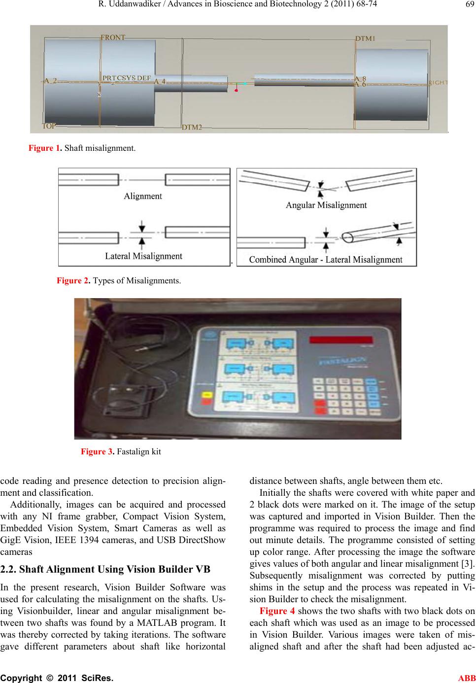 R. Uddanwadiker / Advances in Bioscience and Biotechnology 2 (2011) 68-74 Copyright © 2011 SciRes. ABB 69 Figure 1. Shaft misalignment. Figure 2. Types of Misalignments. Figure 3. Fastalign kit code reading and presence detection to precision align- ment and classification. Additionally, images can be acquired and processed with any NI frame grabber, Compact Vision System, Embedded Vision System, Smart Cameras as well as GigE Vision, IEEE 1394 cameras, and USB DirectShow cameras 2.2. Shaft Alignment Using Vision Builder VB In the present research, Vision Builder Software was used for calculating the misalignment on the shafts. Us- ing Visionbuilder, linear and angular misalignment be- tween two shafts was found by a MATLAB program. It was thereby corrected by taking iterations. The software gave different parameters about shaft like horizontal distance between shafts, angle between them etc. Initially the shafts were covered with white paper and 2 black dots were marked on it. The image of the setup was captured and imported in Vision Builder. Then the programme was required to process the image and find out minute details. The programme consisted of setting up color range. After processing the image the software gives values of bo th angu lar an d lin ear misalign ment [3]. Subsequently misalignment was corrected by putting shims in the setup and the process was repeated in Vi- sion Builder to check the misalignment. Figure 4 shows the two shafts with two black dots on each shaft which was used as an image to be processed in Vision Builder. Various images were taken of mis- aligned shaft and after the shaft had been adjusted ac- 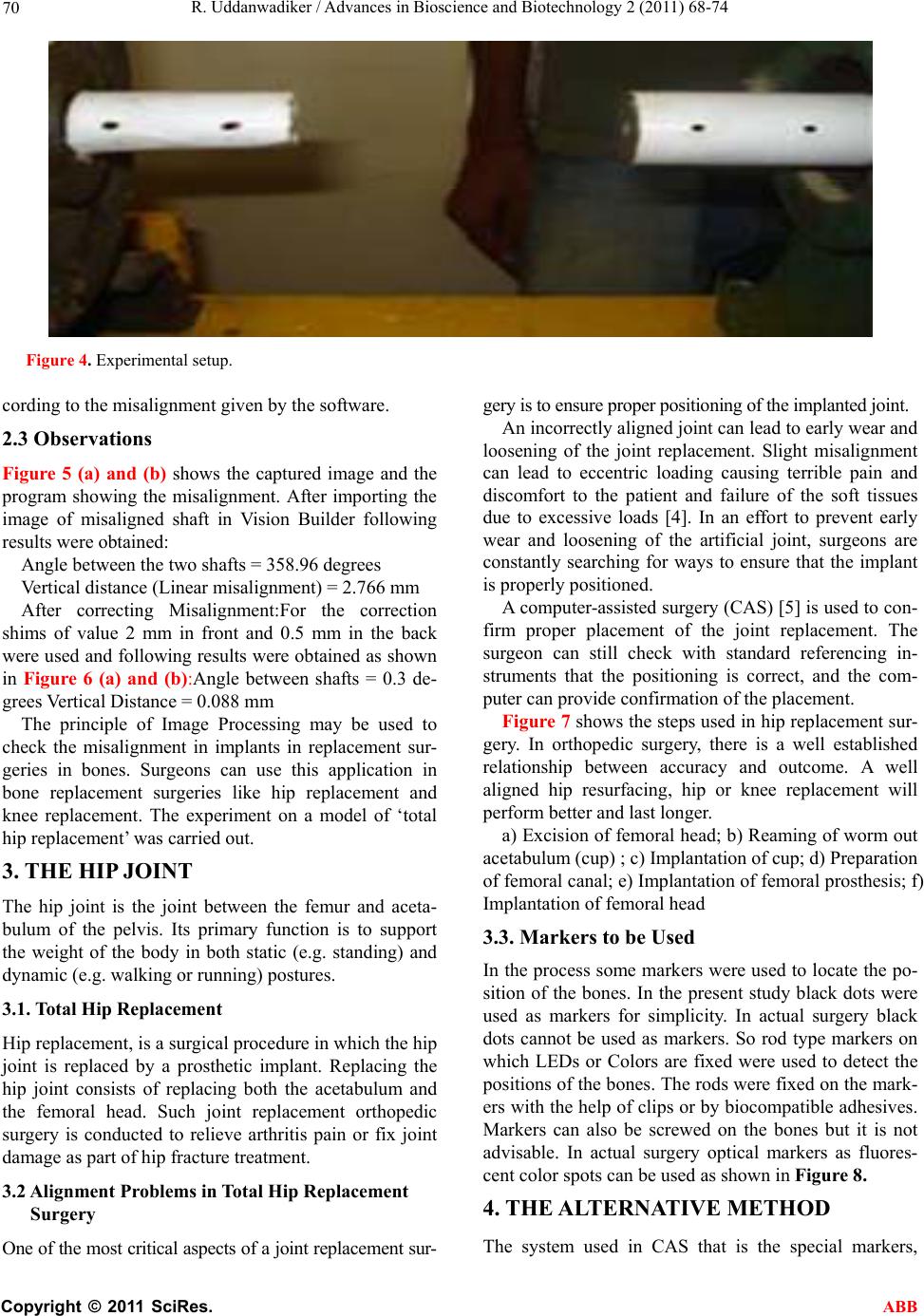 R. Uddanwadiker / Advances in Bioscience and Biotechnology 2 (2011) 68-74 Copyright © 2011 SciRes. ABB 70 Figure 4. Experimental setup. cording to the misalign ment given by the software. 2.3 Observations Figure 5 (a) and (b) shows the captured image and the program showing the misalignment. After importing the image of misaligned shaft in Vision Builder following results were obtained: Angle between the two sha ft s = 358.9 6 de grees Vertical distance (Linear misalignment) = 2.766 mm After correcting Misalignment:For the correction shims of value 2 mm in front and 0.5 mm in the back were used and following results were obtain ed as shown in Figure 6 (a) and (b):Angle between shafts = 0.3 de- grees Vertical Distance = 0.088 mm The principle of Image Processing may be used to check the misalignment in implants in replacement sur- geries in bones. Surgeons can use this application in bone replacement surgeries like hip replacement and knee replacement. The experiment on a model of ‘total hip replacement’ was carried out. 3. THE HIP JOINT The hip joint is the joint between the femur and aceta- bulum of the pelvis. Its primary function is to support the weight of the body in both static (e.g. standing) and dynamic (e.g. walking or runn ing) postures. 3.1. Total Hi p Repl a cement Hip replacement, is a surgical procedure in which the hip joint is replaced by a prosthetic implant. Replacing the hip joint consists of replacing both the acetabulum and the femoral head. Such joint replacement orthopedic surgery is conducted to relieve arthritis pain or fix joint damage as part of hip fracture treatment. 3.2 Alignment Problems in Total Hip Replacement Surgery One of the most critic al aspects of a join t replace ment sur- gery is to ensure proper positioning of the implanted joint. An incorrectly aligned joint can lead to early wear and loosening of the joint replacement. Slight misalignment can lead to eccentric loading causing terrible pain and discomfort to the patient and failure of the soft tissues due to excessive loads [4]. In an effort to prevent early wear and loosening of the artificial joint, surgeons are constantly searching for ways to ensure that the implant is properly positioned. A computer-assisted surgery (CAS) [5] is used to con- firm proper placement of the joint replacement. The surgeon can still check with standard referencing in- struments that the positioning is correct, and the com- puter can provide confirmation of the placement. Figure 7 shows the steps used in hip replacement sur- gery. In orthopedic surgery, there is a well established relationship between accuracy and outcome. A well aligned hip resurfacing, hip or knee replacement will perform better and last longer. a) Excision of femoral head; b) Reaming of worm out acetabulum (cup) ; c) Implantation of cup; d) Preparation of femoral canal; e) Implantation of femoral prosthesis; f) Implantation of femoral head 3.3. Markers to be Used In the process some markers were used to locate the po- sition of the bones. In the present study black dots were used as markers for simplicity. In actual surgery black dots cannot be used as markers. So rod type markers on which LEDs or Colors are fixed were used to detect the positions of the bones. The ro ds were fixed on the mark- ers with the help of clips or by biocompatible adhesives. Markers can also be screwed on the bones but it is not advisable. In actual surgery optical markers as fluores- cent color spots can be used as shown in Figure 8. 4. THE ALTERNATIVE METHOD The system used in CAS that is the special markers, 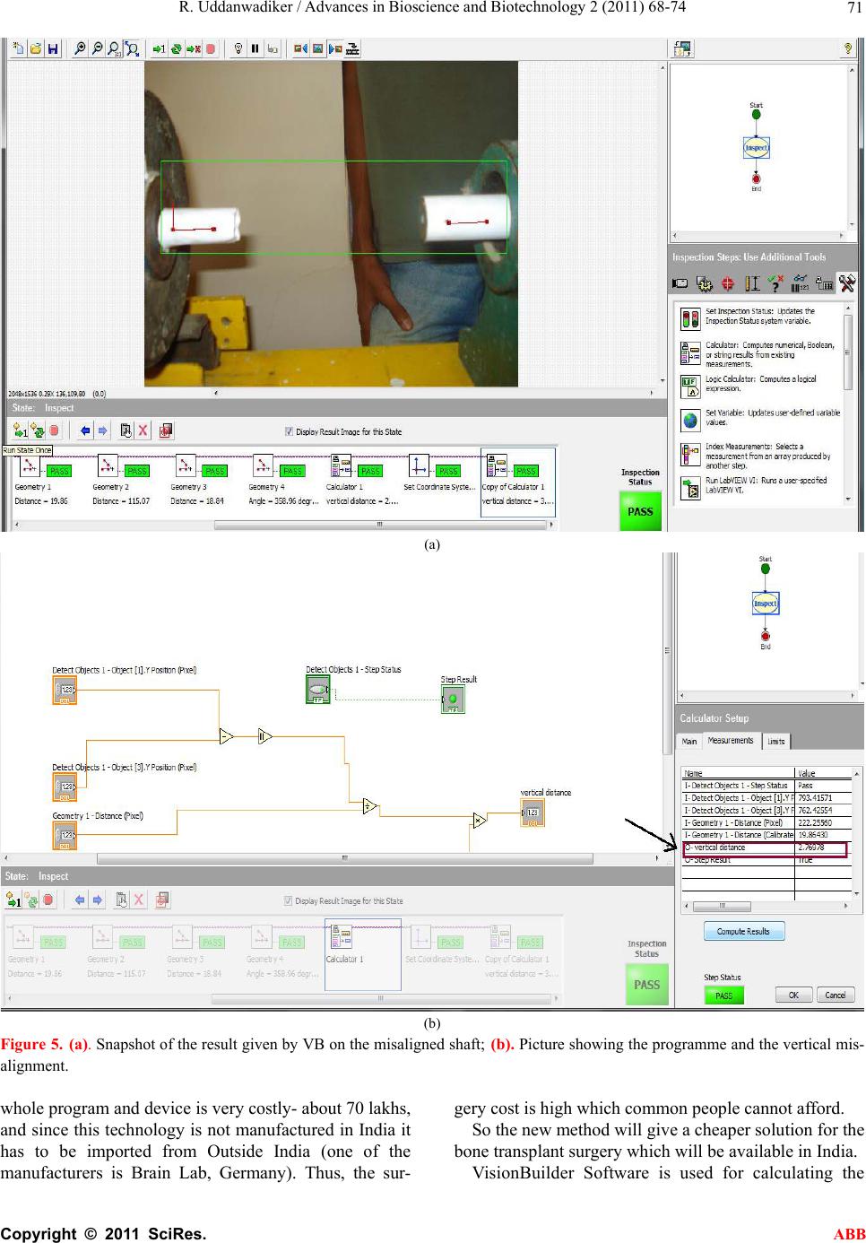 R. Uddanwadiker / Advances in Bioscience and Biotechnology 2 (2011) 68-74 Copyright © 2011 SciRes. ABB 71 (a) (b) Figure 5. (a). Snapshot of the result given by VB on the misaligned shaft; (b). Picture showing the programme and the vertical mis- alignment. whole program and device is very costly- about 70 lakhs, and since this techno logy is not manufactured in India it has to be imported from Outside India (one of the manufacturers is Brain Lab, Germany). Thus, the sur- gery cost is high which common people cannot afford. So the new method will give a cheaper solution for the bone transplant surgery which will be available in India. VisionBuilder Software is used for calculating the 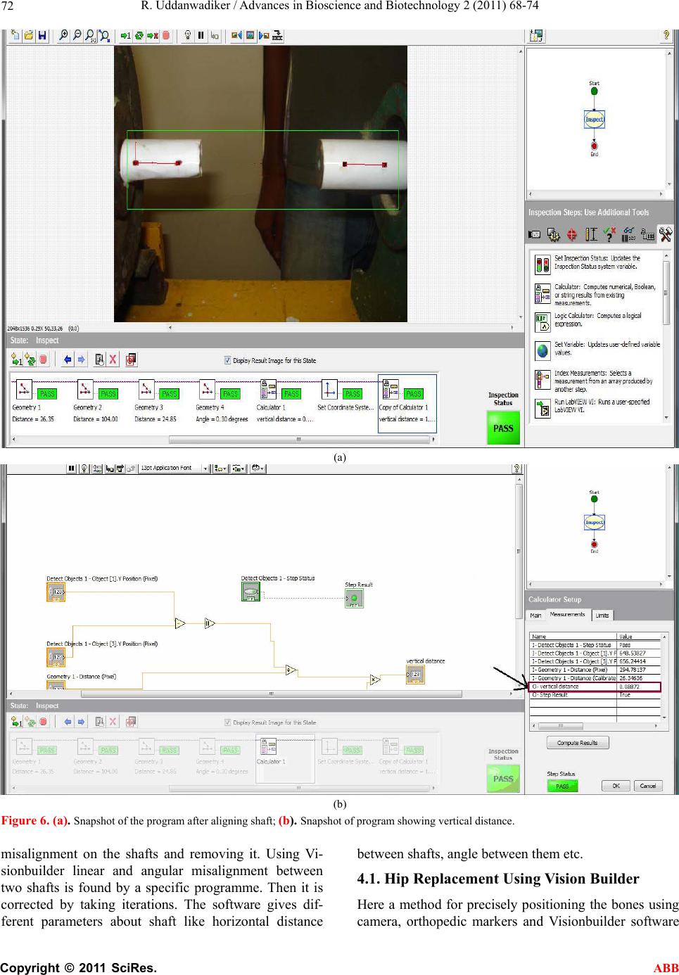 R. Uddanwadiker / Advances in Bioscience and Biotechnology 2 (2011) 68-74 Copyright © 2011 SciRes. ABB 72 (a) (b) Figure 6. (a). Snapshot of the program after aligning shaft; (b). Snapshot of program showing vertical distance. misalignment on the shafts and removing it. Using Vi- sionbuilder linear and angular misalignment between two shafts is found by a specific programme. Then it is corrected by taking iterations. The software gives dif- ferent parameters about shaft like horizontal distance between shafts, angle between them etc. 4.1. Hip Replacement Using Vision Builder Here a method for precisely positioning the bones using camera, orthopedic markers and Visionbuilder software 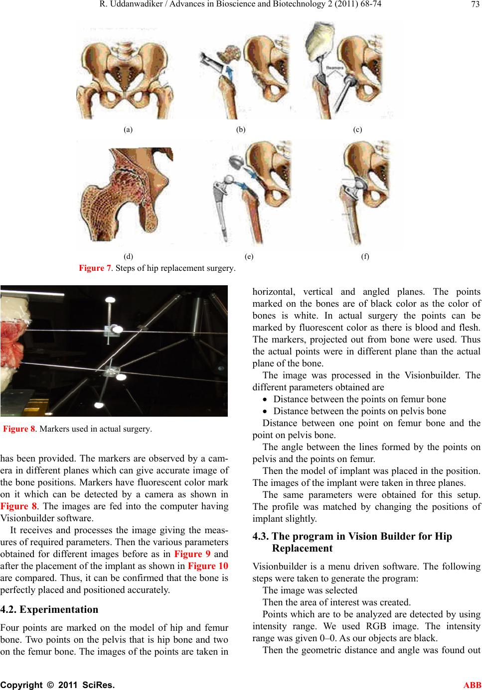 R. Uddanwadiker / Advances in Bioscience and Biotechnology 2 (2011) 68-74 Copyright © 2011 SciRes. ABB 73 (a) (b) (c) (d) (e) (f) Figure 7. Steps of hip replacement surgery. Figure 8. Markers used in actual surgery. has been provided. The markers are observed by a cam- era in different planes which can give accurate image of the bone positions. Markers have fluorescent color mark on it which can be detected by a camera as shown in Figure 8. The images are fed into the computer having Visionbuilder so ftware. It receives and processes the image giving the meas- ures of required parameters. Then the various parameters obtained for different images before as in Figure 9 and after the placement of the implant as shown in Figure 10 are compared. Thus, it can be confirmed that the bone is perfectly placed and positioned accurately. 4.2. Experimentation Four points are marked on the model of hip and femur bone. Two points on the pelvis that is hip bone and two on the femur bone. The images of the points are taken in horizontal, vertical and angled planes. The points marked on the bones are of black color as the color of bones is white. In actual surgery the points can be marked by fluorescent color as there is blood and flesh. The markers, projected out from bone were used. Thus the actual points were in different plane than the actual plane of the bone. The image was processed in the Visionbuilder. The different parameters obtained are Distance between the points on femur bone Distance between the poin ts on pelvis bone Distance between one point on femur bone and the point on pelvis bone. The angle between the lines formed by the points on pelvis and the points on femur. Then the model of implant was placed in the position. The images of the implant were taken in three planes. The same parameters were obtained for this setup. The profile was matched by changing the positions of implant slightly. 4.3. The program in Vision Builder for Hip Replacement Visionbuilder is a menu driven software. The following steps were taken to generate the program: The image was selected Then the area of interest was created. Points which are to be analyzed are detected by using intensity range. We used RGB image. The intensity range was given 0–0 . As our objects are blac k. Then the geometric distance and angle was found out 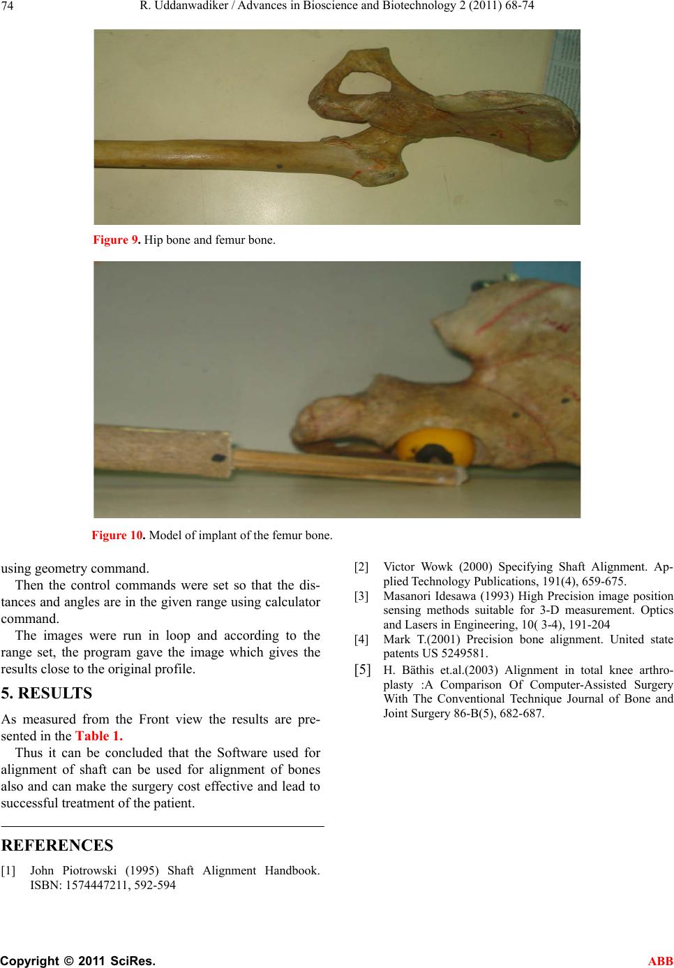 R. Uddanwadiker / Advances in Bioscience and Biotechnology 2 (2011) 68-74 Copyright © 2011 SciRes. ABB 74 Figure 9. Hip bone and femur bone. Figure 10. Model of implant of the femur bone. using geometry command. Then the control commands were set so that the dis- tances and angles are in the given range using calculator command. The images were run in loop and according to the range set, the program gave the image which gives the results close to the original profile. 5. RESULTS As measured from the Front view the results are pre- sented in the Table 1. Thus it can be concluded that the Software used for alignment of shaft can be used for alignment of bones also and can make the surgery cost effective and lead to successful treatment of the patient. REFERENCES [1] John Piotrowski (1995) Shaft Alignment Handbook. ISBN: 1574447211, 592-594 [2] Victor Wowk (2000) Specifying Shaft Alignment. Ap- plied Technology Publications, 191(4), 659-675. [3] Masanori Idesawa (1993) High Precision image position sensing methods suitable for 3-D measurement. Optics and Lasers in Engineering, 10( 3-4), 191-204 [4] Mark T.(2001) Precision bone alignment. United state patents US 5249581. [5] H. Bäthis et.al.(2003) Alignment in total knee arthro- plasty :A Comparison Of Computer-Assisted Surgery With The Conventional Technique Journal of Bone and Joint Surgery 86-B(5), 682-687. |