Paper Menu >>
Journal Menu >>
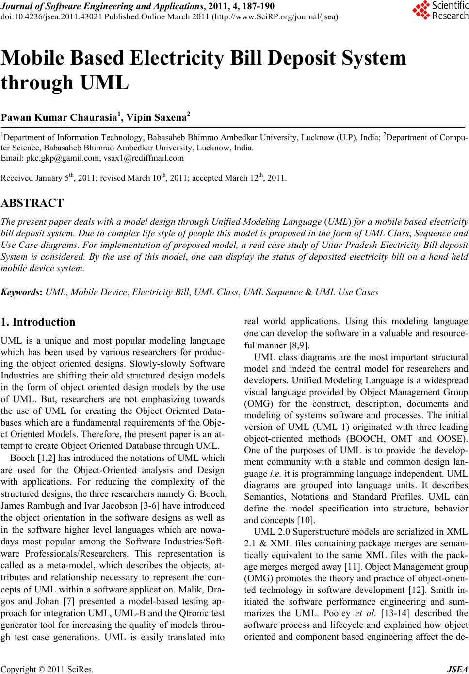 Journal of Software Engineering and Applications, 2011, 4, 187-190 doi:10.4236/jsea.2011.43021 Published Online March 2011 (http://www.SciRP.org/journal/jsea) Copyright © 2011 SciRes. JSEA 187 Mobile Based Electricity Bill Deposit System through UML Pawan Kumar Chaurasia1, Vipin Saxena2 1Department of Information Technology, Babasaheb Bhimrao Ambedkar University, Lucknow (U.P), India; 2Department of Compu- ter Science, Babasaheb Bhimrao Ambedkar University, Lucknow, India. Email: pkc.gkp@gamil.com, vsax1@rediffmail.com Received January 5th, 2011; revised March 10th, 2011; accepted March 12th, 2011. ABSTRACT The presen t paper dea ls with a mode l design through Unified Mod eling Languag e (UML) for a mobile based electricity bill deposit system. Due to comp lex life style of people this model is proposed in the fo rm of UML Class, Sequence and Use Case diagrams. For implementation of propo sed model, a real ca se study of Uttar Pradesh Electricity Bill deposit System is considered. By the use of this model, one can display the status of deposited electricity bill on a hand held mobile device system. Keywords: UML, Mobile Device, Electricity Bill, UML Class, UML Sequence & UML Use Cases 1. Introduction UML is a unique and most popular modeling language which has been used by various researchers for produc- ing the object oriented designs. Slowly-slowly Software Industries are shifting their old structured design models in the form of object oriented design models by the use of UML. But, researchers are not emphasizing towards the use of UML for creating the Object Oriented Data- bases which are a fundamental requirements of the Obje- ct Oriented Models. Therefore, the present paper is an at- tempt to create Object Oriented Database through UML. Booch [1,2] has introduced the notations of UML which are used for the Object-Oriented analysis and Design with applications. For reducing the complexity of the structured designs, the three researchers namely G. Booch, James Rambugh and Ivar Jacobson [3-6] have introduced the object orientation in the software designs as well as in the software higher level languages which are nowa- days most popular among the Software Industries/Soft- ware Professionals/Researchers. This representation is called as a meta-model, which describes the objects, at- tributes and relationship necessary to represent the con- cepts of UML within a software application. Malik, Dra- gos and Johan [7] presented a model-based testing ap- proach for integ ration UML, UML-B and the Qtronic test generator tool for increasing the quality of models throu- gh test case generations. UML is easily translated into real world applications. Using this modeling language one can develop the software in a valuable and resource- ful manner [8,9]. UML class diagrams are the most important structural model and indeed the central model for researchers and developers. Unified Modeling Language is a widespread visual language provided by Object Management Group (OMG) for the construct, description, documents and modeling of systems software and processes. The initial version of UML (UML 1) originated with three leading object-oriented methods (BOOCH, OMT and OOSE). One of the purposes of UML is to provide the develop- ment community with a stable and common design lan- guage i.e. it is programming language independent. UML diagrams are grouped into language units. It describes Semantics, Notations and Standard Profiles. UML can define the model specification into structure, behavior and concepts [10]. UML 2.0 Superstructure models are serialized in XML 2.1 & XML files containing package merges are seman- tically equivalent to the same XML files with the pack- age merges merged away [11]. Object Management group (OMG) promotes the theory and practice of object-orien- ted technology in software development [12]. Smith in- itiated the software performance engineering and sum- marizes the UML. Pooley et al. [13-14] described the software process and lifecycle and explained how object oriented and component based engineering affect the de-  Mobile Based Electricity Bill Deposit System through UML Copyright © 2011 SciRes. JSEA 188 sign process. In the present work, object oriented database has been created for a real case study of Uttar Pradesh Electricity Bill Deposit System. Recently Government of Madhya Pradesh started the online electricity billing through In- ternet using cash card [15]. In the current Electricity Bill Deposit System, customer has to go to the Bill Section of the Electricity Department and can pay through cash or cheque. But by the use of proposed model, the Customer can pay the amount of Electricity Bill through a hand held Mobile Device by entering the credit/debit card number and within a few seconds, customer will get a SMS of the paid amount. In the proposed model, a UML Class, Sequence and UML Use Case diagrams are given. 2. Uml Modeling for Electricity Bill Deposit System 2.1. UML Class Diagram The static representation of the software problems can be explained by the of the UML Class diagram. The purpose of a class diagram is to depict the classes within a model. In an object oriented application, classes have attributes, operations and relationships with other classes. The pre- sent work emphasized on the object oriented databases as shown in the following Figure 1. In this diagram, a cus- tomer (CUSTOMER Class) has a mobile device (MO- BILE_DEVICE Class) and card (CARD Class) which may be credited (CREDIT_CARD Class) or debit (DEBIT_ Figure 1. UML class diagram for mobile based electricity bill deposit system. 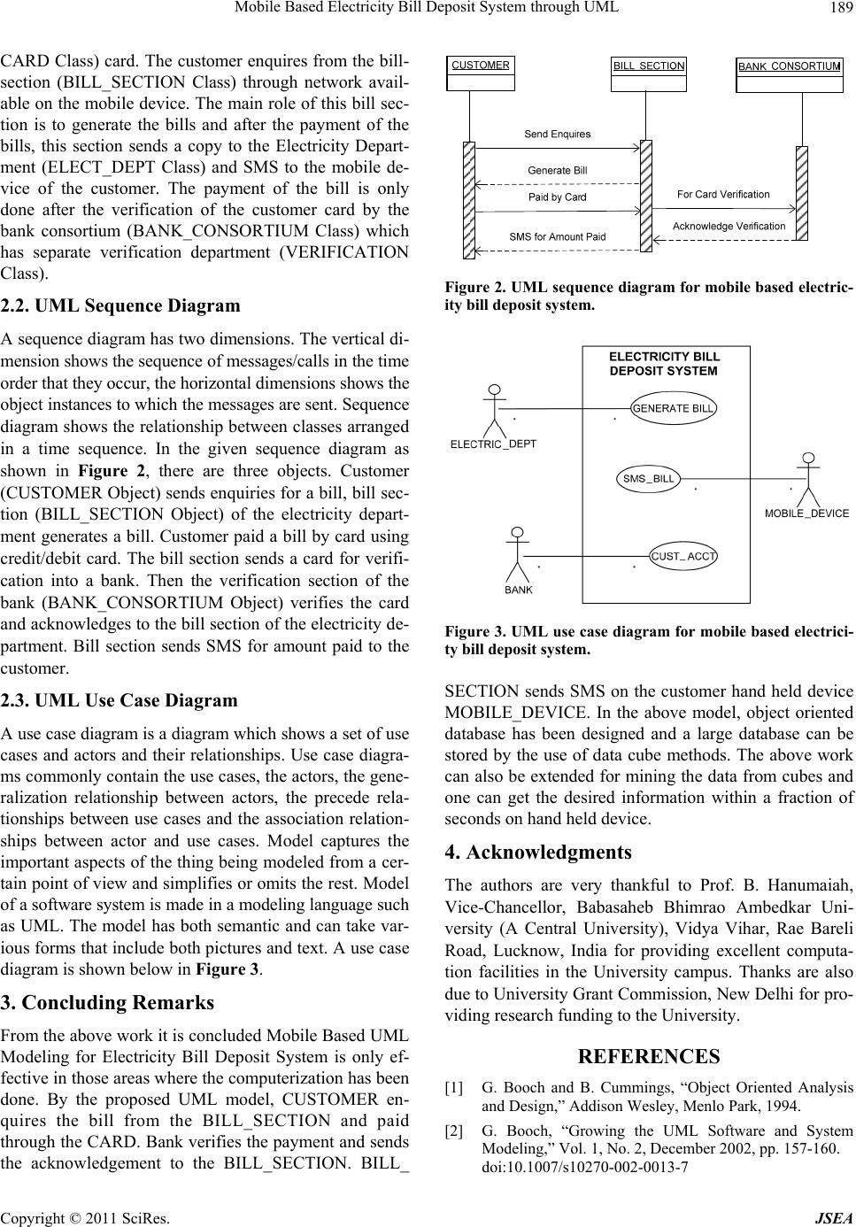 Mobile Based Electricity Bill Deposit System through UML Copyright © 2011 SciRes. JSEA 189 CARD Class) card. The customer enquires from the bill- section (BILL_SECTION Class) through network avail- able on the mobile device. The main role of this b ill sec- tion is to generate the bills and after the payment of the bills, this section sends a copy to the Electricity Depart- ment (ELECT_DEPT Class) and SMS to the mobile de- vice of the customer. The payment of the bill is only done after the verification of the customer card by the bank consortium (BANK_CONSORTIUM Class) which has separate verification department (VERIFICATION Class). 2.2. UML Sequence Diagram A sequence diagram has two dimensions. The vertical di- mension shows the sequence of messages/calls in the time order that they occur, the horizontal dimensions shows the object instances to which the messages are sent. Sequence diagram shows the relationship between classes arranged in a time sequence. In the given sequence diagram as shown in Figure 2, there are three objects. Customer (CUSTOMER Object) sends enquiries for a b ill, bill sec- tion (BILL_SECTION Object) of the electricity depart- ment generates a bill. Customer paid a bill by card using credit/debit card. The bill section sends a card for verifi- cation into a bank. Then the verification section of the bank (BANK_CONSORTIUM Object) verifies the card and acknowledges to th e bill section of the electricity de- partment. Bill section sends SMS for amount paid to the customer. 2.3. UML Use Case Diagram A use case diagram is a diagram which shows a set of use cases and actors and their relationships. Use case diagra- ms commonly contain the use cases, the actors, the gene- ralization relationship between actors, the precede rela- tionships between use cases and the association relation- ships between actor and use cases. Model captures the important aspects of the thing being modeled from a cer- tain point of view and simplifies or omits the rest. Model of a software system is made in a modeling language such as UML. The model has both semantic and can take var- ious forms that include both pictures and text. A use case diagram is shown below in Figure 3. 3. Concluding Remarks From the above work it is concluded Mobile Based UML Modeling for Electricity Bill Deposit System is only ef- fective in those areas where the computerization has been done. By the proposed UML model, CUSTOMER en- quires the bill from the BILL_SECTION and paid through the CARD . Bank verifies the payment and sends the acknowledgement to the BILL_SECTION. BILL_ Figure 2. UML sequence diagram for mobile based electric- ity bill deposit system. Figure 3. UML use case diagram for mobile based electrici- ty bill deposit system. SECTION sends SMS on the customer hand held device MOBILE_DEVICE. In the above model, object oriented database has been designed and a large database can be stored by the use of data cube methods. The above work can also be extended for mining the data from cubes and one can get the desired information within a fraction of seconds on han d hel d device. 4. Acknowledgments The authors are very thankful to Prof. B. Hanumaiah, Vice-Chancellor, Babasaheb Bhimrao Ambedkar Uni- versity (A Central University), Vidya Vihar, Rae Bareli Road, Lucknow, India for providing excellent computa- tion facilities in the University campus. Thanks are also due to University Gran t Commission , New Delhi fo r pro- viding research funding to th e University. REFERENCES [1] G. Booch and B. Cummings, “Object Oriented Analysis and Design,” Addison Wesley, Menlo Park, 1994. [2] G. Booch, “Growing the UML Software and System Modeling,” Vol. 1, No. 2, December 2002, pp. 157-160. doi:10.1007/s10270-002-0013-7  Mobile Based Electricity Bill Deposit System through UML Copyright © 2011 SciRes. JSEA 190 [3] G. Booch, “Object Solutions: Managing the Object Oriented Project,” Addison Wesley, Menlo Park, 1996. [4] G. Booch, J. Rumbaugh and I. Jacobson, “The Unified Modelling Language User Guide,” Addison-Wesley, Reading, 1999. [5] J. Rumbaugh, M. Blaha, W. Lorensen and F. Eddy, “Ob- ject Oriented Modeling and Design,” Prentice Hall, En- glewood Cliffs, 1991. [6] I. Jacobson “Object Oriented Software Engineering: A Use Case Driven Approach”, Addison Wesley, New York, 1992. [7] Q. A. Malik, D. Truscan and J. Lilius, “Using UML Models and Formal Verification in Model-Based Test- ing,” 17th IEEE International Conference and Workshops on the Engineering of Computer-Based Systems, Oxford, 22-26 March 2010, pp. 50-56. [8] S. K. Mostéfaoui, “A Context Model Based on UML and XML Schema Representations,” Proceedings of the IEEE/ACS International Conference on Computer Sys- tems and Applications, 31 March-4 April 2008, Doha, pp. 810-814. [9] J. Rumbaugh, I. Jacobson and G. Booch, “The Unified Modeling Language Reference Manual,” Addison-Wes- ley, Reading, 1999. [10] OMG “Unified Modeling Language Specification,” 2010. http://www.omg.org. [11] OMG, “UML Superstructure Specification, V2.0,” 2004. http://www.omg.org/cgi-bindoc?formal/05- 07-04. [12] OMG, “Unified Modeling Language Specification, Ver- sion 1.3,” June 1999. http://www.rational.com/media/uml/post.pdf [13] R. Pooley and P. King, “The Unified Modeling and Per- formance Engineering,” Proceedings of IEEE Software, Vol. 146, No. 1, February 1999, pp. 2-10. doi:10.1049/ip-sen:19990151 [14] R. Pooley and P. Stevens, “Using UML: Software Engi- neering with Object and Components,” Addison-Wesley Longman, California, 2000. [15] “How to Pay Electricity Bill through MPOnline,” 30 September 2010. http://www.mponline.gov.in |