Low Carbon Economy, 2011, 2, 20-25
doi:10.4236/lce.2011.21004 Published Online March 2011 (http://www.SciRP.org/journal/lce)
Copyright © 2011 SciRes. LCE
The Comparative Study of Fatigue Crack
Propagation Experiment and Computer
Simulation on the Component Materials for the
Crane Life Remained
Sangyeol Kim1, Hyungsub Bae1, Myeongkwan Park1, Seongsoo Kim2, Hanshik Chung2,
Heekyu Choi3
1School of Mechanical of Engineering, Pusan National University, Busan, Korea; 2Department of Precision & Mechanical Engineer-
ing and Eco-Friendly Heat & Cold Energy Mechanical Research Team, Gyeongsang National University, Gyeongnam, Korea;
3School of Nano & Advanced Materials Engineering, Changwon National University, Gyeongnam, Korea.
Email: hkchoi99@changwon.ac.kr
Received November 24th, 2010; revised December 13th, 2010; accepted January 10th, 2011.
ABSTRACT
This study presents fatigue crack propagation experiments and the simulation used to estimate the life remaining in a
crane that is currently in use at a port. The fatigue crack propagation experiments were performed by an Instron 8516
fatigue testing machine and the simulation was performed using the AFGROW software. The simulation results indi-
cated that the critical size of the crack in the upper flange surface of the main jib was 107.4 mm and that it would take
818 000 cycles to reach that point. If the main jib of the crane undertakes 28 800 cycles per annum then its remaining
lifespan should be 28.4 years.
Keywords: Crane, Fatigue Crack Propagation, Computer Simulation, Crane Life Remained
1. Introduction
The cracks in a crane installed in a port are propagated
by the repeated operation of the crane over a long period
of time. A crane may fail, causing a serious accident, if a
crack exceeds its critical size. The analysis of fatigue
crack propagation is the most important factor in the
analysis of the stability and lifespan of the crane but it
may require time and expense to investigate it experi-
mentally. Computer simulation is especially useful for
studying the flow of granular assemblies or powders in
cases where it is difficult to obtain detailed results by
direct experimentation [1-3]. Hence, in order to be effi-
cient, the fatigue crack propagation software should es-
timate the remaining life of the crane experimentally and
by simulation. The fatigue crack can be analyzed by
non-destructive testing of the main jib, which is subject
to severe vibration and fatigue [4]. The critical size of the
crack in the main jib can be calculated using the material
constants which have been derived experimentally and
from the constant amplitude crack propagation curve,
crack size-life data and curve using the AFGROW crack
propagation software. The crane’s remaining lifespan can
be deduced from the simulation results for the main jib
[5].
2. Theoretical Background
Most of the current research on crack propagation uses
the widely accepted Paris Equation [6].
In this equation

dd Δm
aN CK (1)
where C and m are material constants, and K is the
stress intensity range Kmax Kmin.
Δ=ΔπKfg σa (2)
where f(g) is the correction factor that depends on the
geometry of the specimen and the crack,
(
max
min)
and a is the crack size. Substituting into the Paris equa-
tion yields

dd Δπ
m
aN Cfgσa (3)
Separating variables and integrating gives
The Comparative Study of Fatigue Crack Propagation Experiment and Computer Simulation on the 21
Component Materials for the Crane Life Remained






 
-2 2-2 2
=
- 2Δπ
mmm
if
aa
mC
fgσa



dd
=
Δπ Δπ
211
f f
i i
-m
aa
2
fmm
aa
aa
Na
Cfg σaCfgσ


(4)
where, ai is the initial crack size and af is the final crack
size which must be evaluated as follows.

ΔπKfgσa (5)

22
1
==
π1.12
CC
f
max
KK
aσfg σ





(6)
K is fracture toughness and
is the remote stress applied
to the component.
3. Fatigue Crack Propagation Experiment
and Simulation
Figure 1(a) shows a luff crane that has been in operation
at a port for 20 years. The specification of the crane is:
capacity 40 ton, weight 466ton, height 45 m, rail span 20
m, maximum working radius of jib 33 m and minimum
working radius of jib 9 m. Figure 1(b) shows the crane
modeled by the STAAD.Pro 2004 structural analysis
software [7]. The fatigue stress of the main jib was de-
rived from the basic loads and load combinations based
on Table 1 [8-11].
3.1. Experiment
The remaining lifetime of the crane can be estimated
experimentally with the fatigue crack found by non-de-
structive testing of the main jib, which receives severe
vibration and fatigue. The compact-tension (CT) test
ASTM A36 specimen was made in accordance with
ASTM E647-95a [12] and used to analyze the fatigue
crack found in the main jib of the crane. The specimen
was as thick as the main jib (15 mm). The constant am-
plitude crack propagation data, da/dNK curve and
material constants C and m were derived from the fatigue
crack propagation experiment using an Instron 8516 ma-
chine. C and m are the most effective factors in the Paris
equation as the fatigue crack propagation equation can be
derived from the propagation experiment. The constant
amplitude crack propagation curve, crack size-life diagram
and da/dNK curve were calculated using the governing
equations of fatigue crack propagation based on an adap-
tation of C and m, which were derived experimentally.
An ASTM A36 CT specimen was used in accordance
with the ASTM E647-95a code with the following di-
mensions: thickness 15 mm, a (crack starter notch) 10.16
mm, W 50.8 mm and a/W 0.20 with a chevron notch to
(a)
(b)
Figure 1. (a) General view of level luffing crane in port; (b)
structural model showing maximum working ra d i us.
Table 1. Specification of crane modeled.
Item Data Remark
Rate load 40 ton
Weight 466 ton
Height 45 m
Rail span 20 m
Hoisting speed 30 m/min with rated load
Luffing speed 40 m/min
Slewing speed 1 rpm
Traveling speed 25 m/min allowable
Sea side wheel load 30 ton/wheel allowable
Land side wheel load 30 ton/wheel
Maximum working radius 33 m
Minimum working radius 9 m
Copyright © 2011 SciRes. LCE
The Comparative Study of Fatigue Crack Propagation Experiment and Computer Simulation on the
22
Component Materials for the Crane Life Remained
cause a smooth crack in the tip of the crack [13,14] (see
Figure 2).
Figure 3 shows the equipment used for this experi-
ment. Figure 3(a) shows the fatigue crack propagation
experimental system with 10ton capacity An Instron fa-
tigue experimental machine and servo-hydraulic testing
machine were used to operate the actuator in fatigue ex-
perimental machine. The frequency is 10 Hz constant
amplitude loading with stress ratio R = 0.1 at room tem-
perature, as specified in the ASTM E647-95a code. Fig-
ure 3(b) shows the connections and terminal box for the
fatigue crack propagation experiment. The direct current
potential drop (DCPC) system is shown in Figure 3(c).
Figure 3(d) shows the traveling microscope used to ob-
serve and measure the cracking of the surface.
3.2. Simulation
The main jib is 15 mm thick and 1,590 mm wide. The
fatigue crack propagation simulation is used to calculate
the constant amplitude crack propagation data, crack
size-life data and da/dNK curve, using the material
constants C = 5.11 × 10⁻¹¹ and m = 2.260 [12] which
have been derived experimentally. The input data to the
crack propagation software is: KIC,70kscin , modulus
of longitudinal elasticity 206,843 MPa, yield stress 295.7
MPa (30.17 kg/mm2), Poisson’s ratio = 0.33, R = 0.1,
and the stress multiplication factor = 117.6 MPa (1,200
kg/cm2) with constant amplitude loading.
The NASGRO equation, which has been utilized in the
fatigue growth estimation program at national aeronau-
tics and space administration (NASA), is applied to the
AFGROW software. Forman and Newman at NASA, De
Koning at National Aerospace Laboratory (NLR) and
Henriksen at entertainment software association (ESA)
developed the elements of the NASGRO crack growth
rate equation. It has been implemented in AFGROW [14]
as follows.
Figure 2. Photograph of connecting wires on standard CT
specimen prior to fatigue crack propagation experiment.
(a)
(b)
(c)
(d)
Figure 3. Equipment for fatigue crack propagation experi-
ment. (a) Apparatus, (b) Connections and terminal box, (c)
DCPD system, (d) System for measuring and observing
surface cracking.
Copyright © 2011 SciRes. LCE
The Comparative Study of Fatigue Crack Propagation Experiment and Computer Simulation on the 23
Component Materials for the Crane Life Remained
Δ
1-
d1- Δ
=Δ
d1-
1-
p
th
m
q
max
crit
K
af K
CK
NR K
K











(7)
where C, m, p and q are empirically derived, and

23
012 3
01
01
0
-2 0
2
op
max
K
fK
maxARARAR ARR
AR ARR
AA R
 
 
-
2
(8)
The coefficients are:


1
2
0
1
2 013
301
π
2
0.8250.34 +0.05cos
0.415 0.071
1
21
α
max
0
max 0
σ
Aαα
σ
Aασ σ
AAAA
AAA












Here, is the plane stress/strain constraint factor, and
max/
0 is the ratio of the maximum applied stress to the
flow stress. These values have been provided by the
NASGRO material database for each material.


1
1
2
0
00
1
11
th
CR
th
af
KK
a+aA R


 





(9)
where
K0 threshold stress intensity range at a
a crack size
a0 intrinsic crack size (0.0015in or 0.0000381 m)
Cth threshold coefficient
The values for K0 and Cth are provided by the NAS-
GRO material database for each material. The NASGRO
equation uses the critical stress intensity factor, Kcrit to
account for the thickness effects.
2
0
1
K
t
At
crit
K
IC
KBe
K




 (10)
where:
CIC plane strain fracture toughness (mode I)
Ak fit parameter
Bk fit parameter
t thickness
t0 reference thickness (plane strain condition)
The plane strain condition is:
2
02.5 IC VS
tKσ
(11)
The values for KIC, Ak and Bk are provided by the
NASGRO material database for each material. Although
the plane strain thickness, t0, is defined by Equation (11),
Kcrit will asymptotically approach KIC as the actual
thickness becomes larger than t0.
For part-through cracks, the NASGRO equation uses a
variable KIC in place of Kcrit The value KIC is a material
constant since the developers of the NASGRO equation
felt that the Kcrit value of a part-through crack is not
highly dependent on thickness. The value Kcrit, is calcu-
lated internally and is only used by AFGROW to deter-
mine da/d N. It is not used as a failure criterion.
4. Experimental Results and Estimation of
Remaining Lifetime
The analysis shows the constant amplitude crack propa-
gation curve (see Figure 4). The final crack size is 108.9
mm and 870 000 cycles are needed to reach that point, at
which the crane collapses. The simulation using the
AFGROW software supplies the constant amplitude crack
propagation curve, as shown in Figure 4. The final crack
size is 107.4 mm and 818 000 cycles are needed to reach
that point, at which the crane will collapse. The curve
increases sharply at about 780 000 cycles so it is clear
that the fatigue crack propagates quickly in that region.
The fatigue crack life should be 30.2 years if the cane
is operated for 28 800 cycles per year in accordance with
the experimental results shown in Figure 5 and it should
be 28.4 years if the crane is operated for 28 800 cycles
per year in accordance with the simulation result shown
in Figure 5.
Figure 6 shows that the curve is moderately slow and
Figure 4. Comparison of experimental data and simulation
data on crack propagation vs. number of cycles for main
jib.
Copyright © 2011 SciRes. LCE
The Comparative Study of Fatigue Crack Propagation Experiment and Computer Simulation on the
24
Component Materials for the Crane Life Remained
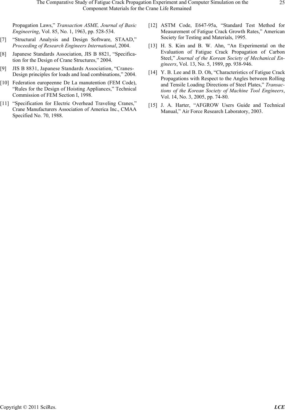
Figure 5. Comparison of experimental data and simulation
data on crack length vs. fatigue life for main jib.
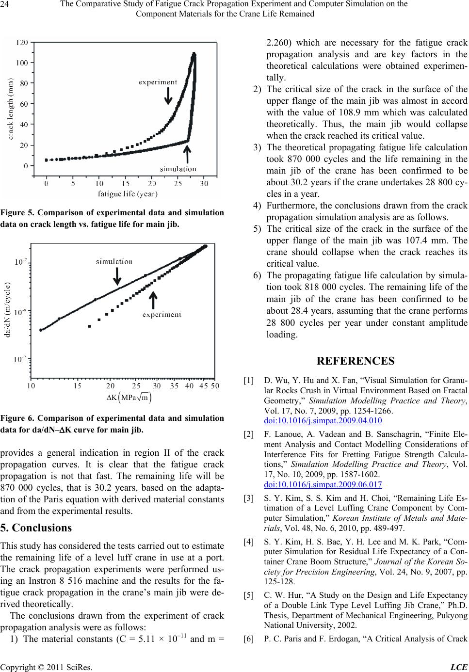
KMPa m
Figure 6. Comparison of experimental data and simulation
data for da/dN–K curve for main jib.
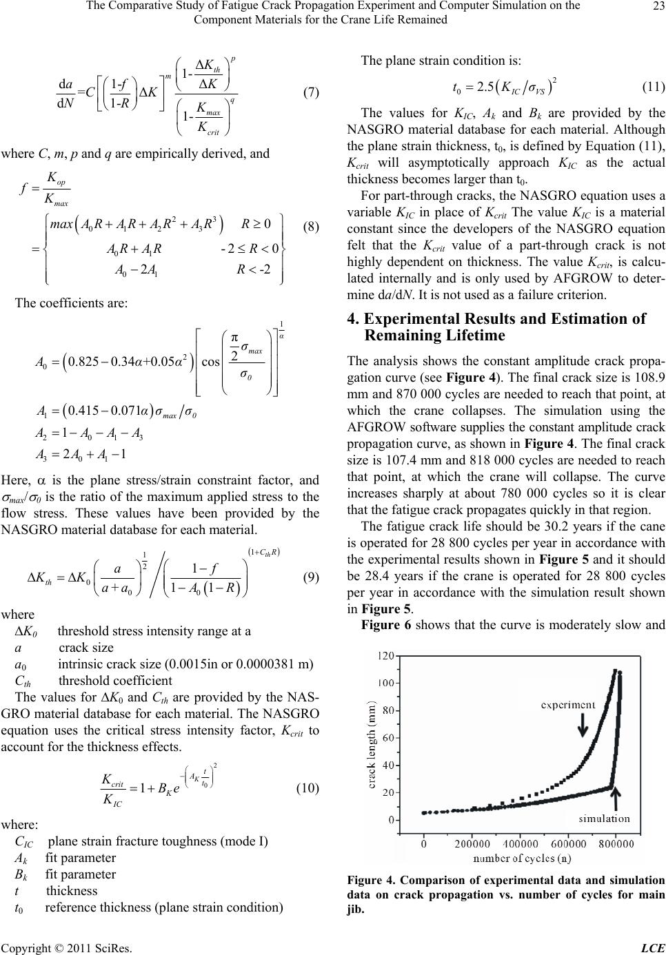
provides a general indication in region II of the crack
propagation curves. It is clear that the fatigue crack
propagation is not that fast. The remaining life will be
870 000 cycles, that is 30.2 years, based on the adapta-
tion of the Paris equation with derived material constants
and from the experimental results.
5. Conclusions
This study has considered the tests carried out to estimate
the remaining life of a level luff crane in use at a port.
The crack propagation experiments were performed us-
ing an Instron 8 516 machine and the results for the fa-
tigue crack propagation in the crane’s main jib were de-
rived theoretically.
The conclusions drawn from the experiment of crack
propagation analysis were as follows:
1) The material constants (C = 5.11 × 10⁻¹¹ and m =
2.260) which are necessary for the fatigue crack
propagation analysis and are key factors in the
theoretical calculations were obtained experimen-
tally.
2) The critical size of the crack in the surface of the
upper flange of the main jib was almost in accord
with the value of 108.9 mm which was calculated
theoretically. Thus, the main jib would collapse
when the crack reached its critical value.
3) The theoretical propagating fatigue life calculation
took 870 000 cycles and the life remaining in the
main jib of the crane has been confirmed to be
about 30.2 years if the crane undertakes 28 800 cy-
cles in a year.
4) Furthermore, the conclusions drawn from the crack
propagation simulation analysis are as follows.
5) The critical size of the crack in the surface of the
upper flange of the main jib was 107.4 mm. The
crane should collapse when the crack reaches its
critical value.
6) The propagating fatigue life calculation by simula-
tion took 818 000 cycles. The remaining life of the
main jib of the crane has been confirmed to be
about 28.4 years, assuming that the crane performs
28 800 cycles per year under constant amplitude
loading.
REFERENCES
[1] D. Wu, Y. Hu and X. Fan, “Visual Simulation for Granu-
lar Rocks Crush in Virtual Environment Based on Fractal
Geometry,” Simulation Modelling Practice and Theory,
Vol. 17, No. 7, 2009, pp. 1254-1266.
doi:10.1016/j.simpat.2009.04.010
[2] F. Lanoue, A. Vadean and B. Sanschagrin, “Finite Ele-
ment Analysis and Contact Modelling Considerations of
Interference Fits for Fretting Fatigue Strength Calcula-
tions,” Simulation Modelling Practice and Theory, Vol.
17, No. 10, 2009, pp. 1587-1602.
doi:10.1016/j.simpat.2009.06.017
[3] S. Y. Kim, S. S. Kim and H. Choi, “Remaining Life Es-
timation of a Level Luffing Crane Component by Com-
puter Simulation,” Korean Institute of Metals and Mate-
rials, Vol. 48, No. 6, 2010, pp. 489-497.
[4] S. Y. Kim, H. S. Bae, Y. H. Lee and M. K. Park, “Com-
puter Simulation for Residual Life Expectancy of a Con-
tainer Crane Boom Structure,” Journal of the Korean So-
ciety for Precision Engineering, Vol. 24, No. 9, 2007, pp.
125-128.
[5] C. W. Hur, “A Study on the Design and Life Expectancy
of a Double Link Type Level Luffing Jib Crane,” Ph.D.
Thesis, Department of Mechanical Engineering, Pukyong
National University, 2002.
[6] P. C. Paris and F. Erdogan, “A Critical Analysis of Crack
Copyright © 2011 SciRes. LCE
The Comparative Study of Fatigue Crack Propagation Experiment and Computer Simulation on the
Component Materials for the Crane Life Remained
Copyright © 2011 SciRes. LCE
25
Propagation Laws,” Transaction ASME, Journal of Basic
Engineering, Vol. 85, No. 1, 1963, pp. 528-534.
[7] “Structural Analysis and Design Software, STAAD,”
Proceeding of Research Engineers International, 2004.
[8] Japanese Standards Association, JIS B 8821, “Specifica-
tion for the Design of Crane Structures,” 2004.
[9] JIS B 8831, Japanese Standards Association, “Cranes-
Design principles for loads and load combinations,” 2004.
[10] Federation europeenne De La manutention (FEM Code),
“Rules for the Design of Hoisting Appliances,” Technical
Commission of FEM Section I, 1998.
[11] “Specification for Electric Overhead Traveling Cranes,”
Crane Manufacturers Association of America Inc., CMAA
Specified No. 70, 1988.
[12] ASTM Code, E647-95a, “Standard Test Method for
Measurement of Fatigue Crack Growth Rates,” American
Society for Testing and Materials, 1995.
[13] H. S. Kim and B. W. Ahn, “An Experimental on the
Evaluation of Fatigue Crack Propagation of Carbon
Steel,” Journal of the Korean Society of Mechanical En-
gineers, Vol. 13, No. 5, 1989, pp. 938-946.
[14] Y. B. Lee and B. D. Oh, “Characteristics of Fatigue Crack
Propagations with Respect to the Angles between Rolling
and Tensile Loading Directions of Steel Plates,” Transac-
tions of the Korean Society of Machine Tool Engineers,
Vol. 14, No. 3, 2005, pp. 74-80.
[15] J. A. Harter, “AFGROW Users Guide and Technical
Manual,” Air Force Research Laboratory, 2003.