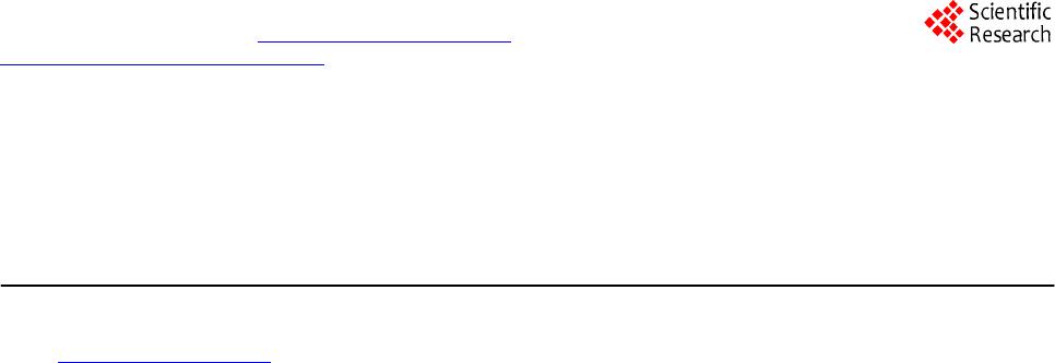
 Journal of Computer and Communications, 2014, 2, 91-96 Published Online January 2014 (http://www.scirp.org/journal/jcc) http://dx.doi.org/10.4236/jcc.2014.22016 OPEN ACCESS JCC On REE and EER Methods for Mining Corner Points on the Images Muhammad Sarfraz1, Zarnawab N. K. Swati2 1Department of Information Science, Kuwait University, Adailiya Campus, Safat, Kuwait; 2Department of Computer Science and Information Technology, Karakoram International University, Gilgit-Baltistan, Pakistan. Email: prof.m.sarfraz@gmail.com Received November 2013 ABSTRACT This paper reviews, implements and compares two corner detection algorithms for mining corner points on the generic shapes. These corner detectors detect corners by using combination of one rectangle (R) and two ellipses (EE). These algorithms have been used with different combinations: REE and EER together with different pa- rameter settings in their descriptions. REE and EER combinations slide along the boundary of the shape and re- cord number of boundary points in each rectangle and ellipses. REE and EER setup represent both local and global views of the image outlines and present natural corner detection methodologies to detect and mine all true corners accurately. A comparative study demonstrates the superiority of the REE and EER over some of the existing algorithms. KEYWORDS Mining; Corner Points; Corner Detector; Planar Curves; Ima ge s 1. Introduction Mining or extracting or detecting of corner points is use- ful for computer applications such as image recognition, segmentation, description, and data compression. Many authors have proposed variety of algorithms in the exist- ing literature [3-13]. Rosenfeld and Johnston [8] use k-cosine angle measurement to find corners. Rosenfeld and Weszka [9] introduce some modifications of [8] in which the maxima of the difference between successive of the averaged k-cosine angle on a digital curve between the k backward and forward vector were used. Freeman and Davis [6] corner detector contains the chain scanned [8] with line sliding along the contour. The change in local curvature is measured by calculating the difference in angles between consecutive segment locations and detects corners where highest change in curve occurs. The corner detector of Beus and Tiu [3] was modification of [6] which introduces an arm limit value τ to specify the upper bound for length of moving line. This paper reviews two corner detection algorithms [12,13] using boundary-based approach. These are dif- ferent from ordinary techniques [3,5,6,8-11] which detect cosine angle for change in the boundary curve. These algorithms define their settings of geometries as a rec- tangle (R) and two ellipses (EE) for global, intermediate and local views respectively. Hence the settings can be denoted as REE [13] which is different from EER which was defined in [12]. Like in [10,11], these algorithms take different scales/views (global, intermediate, local) of boundary curve with defined set of shapes (REE and EER). Different parameters, in the description of REE and EER determine global, intermediate, and local views of the boundary outline curve of an image. These com- binations are sliding along the planar curve and curve points are recorded at each move. Recorded curve points at each step are used for corner selection. In addition to reviewing REE and EER methods, the paper also makes a comparative study of four popular corner detection algorithms [3,4,6,10] for boundary of shapes presented. The proposed techniques are also use- ful to detect corners from generic shape boundaries with or without noise. The organization of the paper is done as follows. Sec- tion 2 gives basic formulation of the technique as well as the design of the proposed corner detection algorithm. A comparative study, with the existing algorithms in the current literature, is made in Section 3. The paper is fi- nally concluded in Section 4. 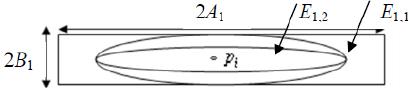 On REE and EER Methods for Mining Corner Points on the Images OPEN ACCESS JCC 2. REE and EER Methods This section presents two algorithms for corner detection. The two algorithms use two ellipses and a rectangle. The algorithm in Section 2.1 uses one rectangle outside two nested ellipses, let us call it as REE. The algorithm in Section 2.2 uses one rectangle inside two nested ellipses, let us call it as EER. 2.1. REE Approach This proposed technique of corner detection is based on rectangle R1 and two ellipses E1,1 and E1,2 sliding along the given curve. The ellipses E1,1 and E1,2 are embedded in R1 such that . The geometry of the rectangle and two ellipses is shown in Figure 1. To gather information about the locality of neighboring curve points, proposed technique uses rectangle and el- lipses shown having common center at pi. The mathematical relations of R1 and two ellipses E1,1 and E1,2 is described in Equation (1). The geometric structure of Figure 1 has been adopted as follows: • The length and width of the rectangle R1 are consi- dered to be the lengths 2A1 and 2B1 respectively. • The semi minor axis and semi major axis of the el- lipse E1,1 are considered to be the lengths 3A1/4 and B1 respectively. • The semi minor axis and semi major axis of the el- lipse E1,2 are considered to be the lengths 3A1/4 and B1/2 respectively. 1 11 1,11 1 1,21 1 22 3 /4 3 /4/2 '' R AB E AB E AB slope S π π θ = × =×× =×× = (1) The length of rectangle and semi major axes of ellipses lies in the direction of slope “S”. Hence the width of rec- tangle and semi minor axes of ellipses lie at right angle to the slope “S” of the contour with center at curve point pi, 1 ≤ i ≤ n, where n is the total number of contour points. Slope of curve point at pi is determined along the line drawn by calculating mean of five points (including pi) on both sides of pi. By taking boundary point pi as center, the direction of rectangle R1 is adjusted along major axes of the Ellipses. Similarly, ellipses E1,1 and E1,2 having same center at pi are configured with same procedure. Thus . Figure 1. Geometrical structure of REE Algorithm. Combination of rectangle and ellipses slides on given curve and number of adjacent points for rectangle and each ellipse. It is recorded from to which lie in the area R1, E1,1, and E1,2. Let nR1,i, nE1,1,i and nE1,2,i describe the total number of curve points in rectangle R1, ellipses E1,1, and E1,2 respectively, with centers at ith boundary point. For example in Figure 2, nR1,i = 23, nE1,1,i = 18, and nE1,2,i = 15. Values of nR1,i, nE1,1,i and nE1,2,i, for each boundary point, are finally used while marking the absolute positions of corner points. Proposed algorithm adopts natural corner detection methodology by combining three levels of views. Com- bination of one rectangle and two ellipses represents three special views of curve points. It traces number of counts nR1,i, nE1,1,i and nE1,2,i, for each boundary point. It calculates sufficient information to mark the absolute corners. Rectangle 1 R represents global view of boun- dary points and allowing only those boundary points for which . These contour points are repre- sented by the set G1 as follows: { } { } −= =−= iii iii nEnRPG nEnRPG ,1,1,1,11 ,1,11 : Or 0: (2 ) Set G1 describes wider view of a shape and does not take false corners (at contour noise/irregularities). This is demonstrated in Figure 3 which shows some snapshots with curves noise/irregularity. Center points pi’s in Fig- ures 3(a) and (b) look like corners if the local view of contour is taken, but if we observed the global view (broader part of the curve), these corners are rejected as they do not qualify the Equation (2). In general, pointing with arrows. Curve points in Figures 3(c) and (d) are only be considered in group G1. Curve points lying in the set G1 are corner points in a relative way, they can be considered as candidate corner points. These points describe common region of contour where the actual corner is located. Set G1 describes con- nected points that represent a group and there is a possi- bility that more than one group may exist in set G1. For each group, there is only single point which represents actual corner. The curve points in E1,2,i of values nE1,2,i less than threshold are calculated for every group and smallest value nE1,2,i is selected as a corner. If in a group the number of points in E1,2,i are lower than then it means that corner point does not exist in that group. The algorithm for REE has been devised in Fig- ure 4. 2.2. EER Approach This proposed technique of corner detection is based on rectangle R2 and two ellipses E2,1 and E2,2 sliding along the given curve. The rectangle R1 is embedded in the 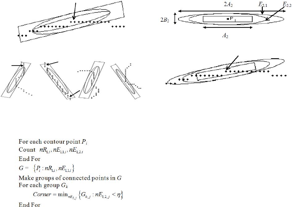 On REE and EER Methods for Mining Corner Points on the Images OPEN ACCESS JCC Figure 2. Snapshot of REE algorithm. (a) (b) (c) (d) Figure 3. Some snapshots of REE Algorithm for irregular boundary. (a), (b) are not qualified by G1, and (c) is re- jected due to threshold ‘η’. Figure 4. Algorithm for REE. embedded ellipses E2,1 and E2,2 such that . The geometry of the rectangle and two ellipses is shown in Figure 5. To gather information about the locality of neighboring curve points, proposed technique uses rec- tangle and ellipses shown having common center at pi. The mathematical relations of R2 and two ellipses E2,1 and E2,2 are described in Equation (3). The geometric structure of Figure 6 has been adopted as follows: • The semi minor axis and semi major axis of the el- lipse E2,1 are considered to be the lengths A2 and B2 respectively. • The semi minor axis and semi major axis of the el- lipse E2,2 are considered to be the lengths 3A2/4 and B2 respectively. • The length and width of the rectangle R1 are consi- dered to be the lengths A2 and B2 respectively. 2,12 2 2,22 2 2 22 3 /4 '' E AB E AB R AB slope S π π θ =×× =×× = × = (3) The length of rectangle and semi major axes of ellipses lies in the direction of slope “S”. Hence the width of rec- Figure 5. Geometrical structure of EER Algorithm. Figure 6. Snapshot of REE Algorithm. tangle and semi minor axes of ellipses lies at right angle to the slope “S” of the contour with center at curve point pi, 1 ≤ i ≤ n, where n is the total number of contour points. Slope of curve point at pi is determined along the line drawn by calculating mean of five points (including pi) on both sides of pi. By taking boundary point pi as center, the direction of rectangle R2 is adjusted along major axes of the Ellipses. Similarly, ellipses E2,1 and E2,2 having same center at pi are configured with same procedure. Thus. Combination of rectangle and ellipses slides on given curve and number of adjacent points for rectangle and each ellipse. It is recorded from to which lie in the area R2, E2,1, and E2,2. Let nR2,i, nE2,1,i and nE2,2,i describe the total number of curve points in rectangle R2, ellipses E2,1, and E2,2 respectively, with centers at ith boundary point. For example in Figure 6, nE1,1,i = 21, nE1,2,i = 18, and nR1,i = 13. Values of nR2,i, nE2,1,i and nE2,2,i, for each boundary point, are finally used while marking the absolute positions of corner points. This algorithm adopts natural corner detection me- thodology (structure of ellipse is just like human eye) by combining three levels of views. Set of two ellipses and one rectangle, described above, takes three different views of contour points. Record of their counts nR2,i, nE2,1,i and nE2,2,i, for each curve point, finds enough in- formation to locate correct corners. Ellipse E2,1 takes broader view of digital curve and passes only those con- tour points for which no part of curve lies in the area E2,1 – E2,2. Such curve points can be described as set G2 as follows in Equation (4): { } { } == =−= iii iii nEnEPG nEnEPG ,2,2,1,2,22 ,2,2,1,2,22 : Or 0: (4) Set G2 represents broader view of image and does not take fake corners (at curve irregularities) as dis- cussed above. For example, Figure 7 shows some snapshots along irregular/noisy curves. Center point in Figures 7(a) and (b) appears to be corners in  On REE and EER Methods for Mining Corner Points on the Images OPEN ACCESS JCC (a) (b) (c) (d) Figure 7. Some snapshots of ellipses sliding over noisy/ire- gular curves. Set G2 of curve does not support (a) and (b); (c) is also rejected as its nE2,2,i value is above the threshold . Figure 8. Algorithm for EER. local view (smaller part of curve is observed) but these are not the valid corners in global view (broader part of curve is observed). The EER algorithm rejected these points, because it does not satisfy the condition of Equa- tion (4). It can be said that, some contour points of curve lie in the area E2,1 – E2,2 indicated with arrows. Curve points in Figures 7(c) and (d) would only be taken in set G2. Curve points lying in set G2 are not simple corners rather it shows general area of curve around the corner point as shown in Figure 7. Set G2 describes connected points which form one group and there may be number of groups in set G2. In each group maximum one corner point can exist. For each group, all points with nR2,i val- ues below threshold “η” are determined and the point with minimum value nR2,i among them is taken as a cor- ner. Curve point in Figure 7(c) is a candidate for corner because it is part of set G2 but does not fall below thre- shold η, thus it cannot be taken as a corner. Sometimes, there is no point in a group with nE2,2,i below η which means corner does not exist in this group. The EER corner detection algorithm is given in Fig- ure 8. In this algorithm, default value of A2 is 14. A2/8 and 3 A2/4 is assigned to B2 and η, respectively. All other parameters are relative to A2 (Figure 5). Value of para- meter A2 depends upon the size of boundary, noise, and resolution of image. Assigned values to semi major axis, semi minor axis, length, and width of ellipses and rec- tangle are suitable to a certain range of size and resolu- tion, which covers all demonstrated shapes in this paper. These sizes were found after extensive testing on many images of similar size and resolution. The relationship between relative size of ellipses and rectangle is set (again with extensive testing) for convenience of using these parameters. The user needs to tune only one para- meter i.e. A2 instead of three. However, accuracy can improve by assigning independent sizes, but this would be at the cost of complex tuning of parameters. 3. Experimental and Comparative Study To measure the accuracy of a corner detection algorithm, the absolute location of corner points must be already known. A board of 10 judges was used to mark the abso- lute position of corner points for standard shapes in Fig- ure 9. Corner positions decided by majority were taken as absolute position of corners [10,11]. These corner po- sitions were used to judge the accuracy of different cor- ner detection algorithms. Detected corners by the REE and EER algorithms were shown in [12,13]. One can see that the corner points, detected by REE and EER, have happened to be the same as detected by human eyes. It is important to note that this evaluation is based on accura- cy, localization error, noise sensitivity, transformation invariance, single response, parameter setting, and com- putation time. Independent tuning of three parameters (A, B and η ) for optimum results, once set appropriately, is enough for most of the shapes. Different corner detection algorithms have been pre- sented for digital boundary and their comparative study has also been described by different authors. To evaluate a corner detection algorithm, it should properly be tested on variety of shapes. Four proposed standard shapes, in Figure 9, contain noise/irregularities along the boundary curves, different types of varying curves, and angle shar- pness. These types of variations are common and proba- ble in real shape contours. These test shapes are used in this paper for comparison/evaluation of different corner detectors. Four popular algorithms, namely BT [3], CS [4], FD [6], AS [10,11] have been taken for comparison in this study. They have been compared with REE and EER algorithms presented in this paper. A study of the six algorithms, in the light of the crite- ria mentioned in Section 3, has been made. Tables 1-5 show the results of the six algorithms for the proposed test shapes in Figure 9. These tables demonstrate a com- parative study among the algorithms. Accuracy results for true corner points detected by FD corner detector were lowest (60%) for standard shapes. It is clearly indicated (in im 3 and im 4) that FD corner detector ignores some true corners. Accurate corners marked by BT corner detector is 72% were better than previous corner detector, but it also tends to miss some important corners (in im4). In case of incorrect corner detection and localization errors, the performance of BT 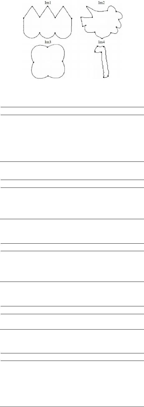 On REE and EER Methods for Mining Corner Points on the Images OPEN ACCESS JCC Figure 9. Test shapes with actual corner points. Table 1. Parameter values assigned for results in Figure 9. FD BT CS AS REE EER im1 D D D D D A = 14, 1.7 Im2 D D D D A = 18 A = 16 B = 2.42 im3 S = 6, K = 2500 D D D D D im4 K = 5, S = 500 S = 500 Dmin = 8, αmax = 140 D D A = 18 Table 2. Number of correctly detected corner points. FD BT CS AS REE EER im1 9 8 9 9 9 9 Im2 8 7 12 12 11 11 im3 3 4 4 4 4 4 im4 4 4 6 6 6 6 Table 3. Number of incorrectly detected corner points in Figure 9. FD BT CS AS REE EER im1 2 2 0 0 0 0 Im2 3 3 9 5 1 0 im3 5 0 0 0 0 0 im4 3 1 4 0 0 0 Table 4. Correct and incorrect detected corners by each al- gorithm. FD BT CS AS REE EER % Correct 60 72 90 99 100 100 % Incorrect 21 10 17 6 1 0 Table 5. Computational time for each algorithm (in se- conds). Algorithm Im2 I m4 Im7 Im8 Avg. Time EER 0.9301 0.7443 1.558 1.7151 1.2369 REE 0.9567 0.7349 1.5195 1.7165 1.2319 AS 0.5631 0.3922 0.8188 1.0922 0.7166 CS 0.0106 0.0101 0.0172 0.0274 0.0163 BT 0.0508 0.0193 0.0662 0.0831 0.0549 FD 0.0253 0.0059 0.0204 0.0247 0.0191 is very good and is less than 10%. CS [4] gives very good results in case of correct corner detection which is 90%, but its false detection rate is high and is 17% which exceeds than BT. Accurate corners marked by AS corner detector are 100%, but it also detects some false corner points in im2. Performance of this algorithm is better with respect to localization errors and false detections which is 5%. A considerable improvement can be seen in REE that correctly marked 100% true corners. Lowest percentage of incorrect detection is 1% which is another big advan- tage of the proposed algorithm. One can hardly find loca- lization error at any detected corner points. Performance of this algorithm must be appreciated in heavy noise conditions as well as complex shapes. No algorithm could accurately find all corners of im2, due to complex shape of the Figure. The proposed algorithm minimizes the incorrect corner(s) detection rate. A significant improvement can also be seen in EER that correctly marked 100% true corners. One can see that no percentage of incorrect detection is found. This is another big advantage of the EER algorithm. One cannot find localization error at any detected corner points. Per- formance of this algorithm must be appreciated in heavy noise conditions as well as complex shapes. No algo- rithm could accurately find all corners of im2, due to complex shape of the figure. The proposed algorithm mi- nimizes the incorrect corner(s) detection rate. 4. Conclusion Two corner detection techniques REE and EER have been reviewed with comparative study. They do not in- volve curvature analysis and determination of cosine angle, hence making it very efficient. A comparative study of different corner detectors, based on proposed parameters, is given. REE and EER corner detectors have various advantages over previous corner detectors accu- racy, localization error, noise sensitivity, transformation invariance, single response, parameter setting, and com- putation time. For the future work, it is proposed to use these algorithms for applications like vectorizing outlines of images [1] and other curve manipulation applications [2]. Acknowledgements This work was supported by Kuwait University, Re- search Grant No. [WI 05/12]. REFERENCES [1] M. Sarfraz, “Vectorizing Outlines of Generic Shapes by Cubic Spline Using Simulated Annealing,” International Journal of Computer Mathematics, Vol. 87, No. 8, 2010, pp. 1736-1751.  On REE and EER Methods for Mining Corner Points on the Images OPEN ACCESS JCC http://dx.doi.org/10.1080/00207160802452519 [2] M. Sarfraz, M. Z. Hussain and M. Hussain, “Shape Preserving Curve Interpolation,” International Journal of Computer Mathematics, Vol. 89, No. 1, 2012, pp. 35-53. http://dx.doi.org/10.1080/00207160.2011.627434 [3] H. L. Beus and S. S. H. Tiu, “An Improved Corner De- tection Algorithm based on Chain Coded Plane Curves,” Pattern Recognition, Vol. 20, 1987, pp. 291-296. http://dx.doi.org/10.1016/0031-3203(87)90004-5 [4] D. Chetverikov and Z. Szabo, “A Simple and Efficient Algorithm for Detection of High Curvature Points in Planner Curves,” Proceedings of 23rd workshop of Aus- tralian Pattern Recognition Group, Steyr, 1999, pp. 175- 184. [5] E. R. Davies, “Application of the Generalized Hough Transform to Corner Detection,” IEEE Proceedings of Computers and Digital Techniques, Vol. 135, No. 1, 1988, pp. 49-54. [6] H. Freeman and L. S. Davis, “A Corner Finding Algo- rithm for Chain-Coded Curves,” IEEE Transactions on Computers, Vol. 26, 1977, pp. 297-303. http://dx.doi.org/10.1109/TC.1977.1674825 [7] H. C. Liu and L. S. Srinath, “Corner Detection from Chain-Code,” Pattern Recognition, Vol. 23, 1990, pp. 51- 68. http://dx.doi.org/10.1016/0031-3203(90)90048-P [8] A. Rosenfeld and E. Johnston, “Angle Detection on Digi- tal Curves,” IEEE Transactions on Computers, Vol. 22, 1973, pp. 875-878. http://dx.doi.org/10.1109/TC.1973.5009188 [9] A. Rosenfeld and J. S. Weszka, “An Improved Method of Angle Detection on Digital Curves,” IEEE Transactions on Computers, Vol. 24, 1975, pp. 940-941. http://dx.doi.org/10.1109/T-C.1975.224342 [10] A. Masood and M. Sarfraz, “A Novel Corner Detector Approach using Sliding Rectangles,” The Proceedings of The 4th ACS/IEEE International Conference on Comput- er Systems and Applications (AICCSA-06), Sharjah, 2006, pp. 621-626. [11] A. Masood and M. Sarfraz, “Corner Detection by Sliding Rectangles along Planar Curves,” International Journal of Computers & Graphics, Vol. 31, No. 3, 2007, pp. 440 -448. http://dx.doi.org/10.1016/j.cag.2007.01.021 [12] Z. N. K. Swati, S. Zaman, and M. Sarfraz, “A Novel Corner Detector Approach using Sliding two Ellipses and one Rectangle,” The Proceedings of International Con- ference on Frontiers of Information Technology (FIT 2009), 16-18 December 2010, Islamabad, Article #73. [13] M. Sarfraz and Z. N. K. Swati, “Mining Corner Points on the Generic Shapes,” Open Journal of Applied Sciences, Vol. 3, No. 1B, 2013, pp. 10-15. http://dx.doi.org/10.4236/ojapps.2013.31B003
|