 Journal of Computer and Communications, 2014, 2, 42-47 Published Online January 2014 (http://www.scirp.org/journal/jcc) http://dx.doi.org/10.4236/jcc.2014.22008 OPEN ACCESS JCC Image Enhancement in Coherent Optical Amplification by Photorefractive Crystals Danyu Chen, Fengchun Tian, Ying Liu, Youwen Hu, Liang Han College of Communication Engineering, Chongqing University, Chongqing, China. Email: fengchuntian@cqu.edu.cn Received November 2013 ABSTRACT In this paper, a model of two-wave mixing in the photorefractive crystal, which takes account of the difference in spatial frequency in a beam, has been built to study the image enhancement effect in coherent optical amplifica- tion. Based on the theoretical analysis of the model, the gain distribution for each pixel in the signal beam has been obtained. It shows that the unevenness of the gain is induced by the difference in spatial frequency in the beam. The factors that impact on the uniformity of image enhancement have been analyzed. As an example, the effects of these factors in a given photorefractive crystal have been studied through simulation. KEYWORDS Coherent Optical Amplification; Photorefractive Effect; Image Enhancement; Unevenness of Gain 1. Introduction Coherent optical amplification, as an interesting pheno- menon of great research and application value in nonli- near optics, has received growing interest in the past four decades. In a photorefractive crystal, two-wave mixing can be explained as the nonlinear interaction of intensity and phase between two incident beams through the pho- torefractive effect [1-3]. Plenty of effective applications of two-wave mixing have been applied to different fields, such as real-time holography, self-pumped phase conju- gation, coherent image amplification, optical storage, etc. [4,5]. As for two-dimensional image enhancement, it is a practical way to make use of photorefractive crystals in two-wave mixing arrangements because of the relative convenient operation and the potential for high gain [6,7]. The gain non-uniformity will introduce serious wave- front distortion and apparent polarization state degrada- tion to the output beam. Especially the induced perturba- tion between the spatial intensity and phase of the beam will cause small-scale self-focusing in the beam and even devastating damage to the elements in the light path. However, most research on coherent image amplification by two-wave mixing in previous literature only empha- sized on the condition of a single spatial frequency [1,8,9]. In this paper, the unevenness of image enhancement in coherent optical amplification by photorefractive crystals, which takes the difference in spatial frequency in a beam into account, has been studied in detail. 2. Theoretical Analysis The model of two-wave mixing in previous literatures, which are concentrated on the situation for a single spa- tial frequency, has been presented in Figure 1. As seen in Figure 1, the two beams and enter into a photorefractive crystal symmetrically. The interfe- rence intensity and refractive index n(x) distribut- ing Equations [6] can be expressed as , (1) , (2) where is the intensity modulation depth; is the saturation value of photo induced refractive index change; k is the value of index gratings wave vec- tor; is the phase offset between the interference in- tensity pattern and refractive index gratings. In order to study the unevenness of gain in coherent optical amplification by photorefractive crystals, a model that takes account of the difference in spatial frequency in a beam has been built. And the geometrical configura- tion has been presented in Figure 2. 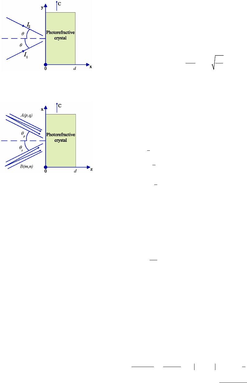 Image Enhancement in Coherent Optical Amplification by Photorefractive Crystals OPEN ACCESS JCC Figure 1. Previous model of two-wave mixing. This is a geometrical configuration with regard to a single spatial frequency. Figure 2. New model of two-wave mixing. This is a geome- trical configuration in view of the different spatial frequen- cies in a beam. As seen in Figure 2, C is the optical axis of the crystal, which is parallel to x-axis. Assuming the pump and sig- nal beam enter into the medium symmetrically with re- spect to the normal (z-axis) from the left side (z = 0). The two beams couple with each other in the crystal, which leads to the enhancement of the signal beam at the ex- pense of the pump beam intensity decrease. For both the pump and signal beam, which are superposition of cracks of light, the optical field analytical expression on each pixel can be represented by ( , )exp[i(( , ))]pqt pq ω and (, )exp[i((, ))] ω separately, where indicates the spatial locations of light on individual pixel in the pump beam, and similarly in the signal beam; p = 1, 2, …, P; q = 1, 2, …, Q; m = 1, 2, …, M; n = 1, 2, …, N; and are separately the wave vectors on each pixel in the pump and signal beam, which can be expressed with the coordinate system in Figure 2. As a small divergence angle will be induced with the spatial propagation in Gaussian beam shot from a laser [10], the pump and signal waves span a rather small an- gular range, which results in different spatial frequencies in a beam. The offsets of the propagation direction on each pixel to the average propagation direction are represented by and separately for the pump and signal waves. Therefore, when entering into the crystal, the incident angle on each pixel in the pump and signal beam can be represented separately by and , where and indicate the average incident angle of the pump and signal beam, respectively. Ordinarily, is assumed. As is known, the far-field small divergence angle of laser beams can be figured out by the formula [11] , (3) where L is the resonant cavity length of the laser, is the wavelength of the beams. Consequently, for the pump and signal waves, and vary over a range of separately, i.e. , the incident angle on each pixel in the signal beam range from to . The interference intensity of the pump and signal waves in the crystal, which has been deduced from Equa- tion (1), can be expressed as ( )()() ( ) ( ) * 011 11 * 11 11 * 1 11 1,,exp i(,)(,) 2 1(,)(, )expi(,)(, ) 4 1( ,)(,)expi( ,)(,) 4 Q P MN pq mn QQ PP pq xy p xq y N MN n jk nk IIA pqBmnpqmn ApqAxypqxy BmnBjkmnjk = == = = == = ≠≠ == = ≠ =+ −⋅ + −⋅ + −⋅ ∑∑ ∑∑ ∑∑ ∑∑ ∑∑ abr aar b br 1 c.c. M m mj = ≠ + ∑∑ (4) where 011 11 =( , ;0)(, ;0) Q P MN ps pq mn IIpqI mn = == = + ∑∑ ∑∑ is the total in- tensity of the incident pump and signal beam; c.c. indi- cates the complex conjugate of the previous term. Based on Equation (2), the refractive index distribu- tion can then be approximated as ( ) * 1 011 11 0 i(,)(,)expi (,)(,) 2 c.c. Q P MN pq mn n nnApqB mnpqmn I = == = =+ −⋅ + ∑∑∑∑ abr (5) where is the refractive index of the crystal when no light is present; is the modulation factor of refractive index, which depends on the spacing and direction of the grating, as well as on the material properties of the crys- tal, e.g., the electro-optic coefficient. Equ ation (5) is solved for the steady state so that the amplitudes and Bmn are taken to be time independent. With this and the slowly varying amplitude approxi- mation [12], Maxwell’s scalar equations yield the fol- lowing coupled amplitude equations 2 11 0 1 (,) d(,;) 1 ( ,;)(,;)(,;) d2 π 1, 2,,;1, 2,,;(,)=cos(, ) MN p mn p pq Apqr BmnrApqrApqr rI n pP qQpqpq γσ γλα = = =−− =…=… ∑∑ (6)  Image Enhancement in Coherent Optical Amplification by Photorefractive Crystals OPEN ACCESS JCC 2 11 0 1 s (,) d( ,;)1 (,;)(,;)( ,;) d2 π 1, 2,,;1, 2,,;(,)=cos(, ) Q P s pq mn Bmnr Apqr BmnrBmnr rI n mM nNmnmn γσ γλβ = = = − =…=… ∑∑ (7) where is the absorption coefficient of the crystal, which is regulated by the wavelength of the incident beam. Since the relation between the intensities and ampli- tudes of the incident beams are and , the coupled intensity equ- ations are given by 11 0 d (,;)(,) =( ,;)(,;)(,;) d 1, 2,,;1, 2,,;(,)=2(,) MN pp sp p mn pp I pqrpqImnrI pqrI pqr rI pP qQpqpq σ γ = = Γ −− =…=…Γ ∑∑ (8) 11 0 s d(,;) (,) =(,;)( ,;)(,;) d 1, 2,,;1, 2,,;(,)=2(,) Q P ss ps s pq s I mnrmnIpqrI mnrI mnr rI mM nNmnmn σ γ = = Γ− =… =…Γ ∑∑ (9) In the assumed diffusion driven scenario, the phases of the beams are decoupled so that the intensity Equations (8) and (9) describe the two-wave mixing process com- pletely. With Equation (8) and Equation (9), one can integrate to yield the intensity versus effectively acting distance r on each pixel in the signal beam, which can be norma- lized by the initial intensity as 11 ( ,) 11 (, ;0) ( ,;)1 == (, ;0)1(, ;0) s Q P p pq r smnrM N s s mn I pq I mnrheh I mnhe I mn σ = = − −Γ = = + + ∑∑ ∑∑ , . (10) Therefore, the gain, which is defined as the intensity ratio of the output signal wave in the presence of a pump beam to that in the absence of a pump beam, can be giv- en by ( ,) (, ;)1 (,)= (, ;0)1 =cos(, ) s l smnl s i I mnlh Gmn e I mnhe d lmn σ β − −Γ + =+, , (11) where d is the thickness of the crystal, is the angle between the propagation direction and the normal (z-axis) on each pixel in the signal beam inside the crys- tal, and l is the effective interaction length on individual pixel in the signal beam. To perform calculation of the gain, the expression of intensity coupling coefficient [13], presented below, can be insert into Equation (11). 22 cos2(, ) sin(, ) (,). cos(,) 1sin(, ) i si mn A mn mn mn B mn β β β β − Γ= + . (12) In Equ ation (12), the related parameters are included in coefficient A and B, which can be given by , (13) , (14) where eff γ is the effective electric-optic coefficient; n is the refractive index; is the recombination con- stant, which is fixed when the value of is set; is the effective charge density, which is regulated by the wavelength of the incident beams; is the Boltzmann constant; T is the absolute temperature; e is the charge on the electron; is the wavelength of the incident beams. According to the analysis above, the gain non- unifor- mity in the signal beam, which indicates the unevenness for image enhancement, is induced by the difference in spatial frequency in the beam. As seen in Equations ( 11-14), the factors, which impact on the unevenness of gain in the signal beam, are the crystal thickness d, the incident angle , and the wavelength . 3. Simulation and Discussion The non-uniformity of gain can be measured with the relative standard deviation = SD/AVG. Here, AVG and SD are the mean value and standard deviation of the gain in the signal image beam, respectively. The gain non-uniformity is negligible compared with the value of gain when reaches a low enough value. The usual requirement is = 1%. In this paper, the numerical simulation for two-wave mixing is based on the model analyzed above. Assuming the signal beam and the pump beam are split from a laser beam at a ratio of 1:1120. Then the two of them recom- bines at a photorefractive () () 3 Fe 0.04wt%:Ce 0.1wt%:LiNbO crystal from the same side with the average incident angle . Three scenarios with different wavelengths have been analyzed to obtain the gain distribution in the signal im- age beam. 3.1. Argon Laser at λ = 488 nm In the first scenario, the light source is an argon laser with a cavity length of L = 150 cm operating at wave- length 488 nm, in which case the crystal has the parame- ters of 1 =21.2cm σ − and ac- cording to [14]. Substituting and L into Equation (3) yields the far-field small divergence angle of the laser 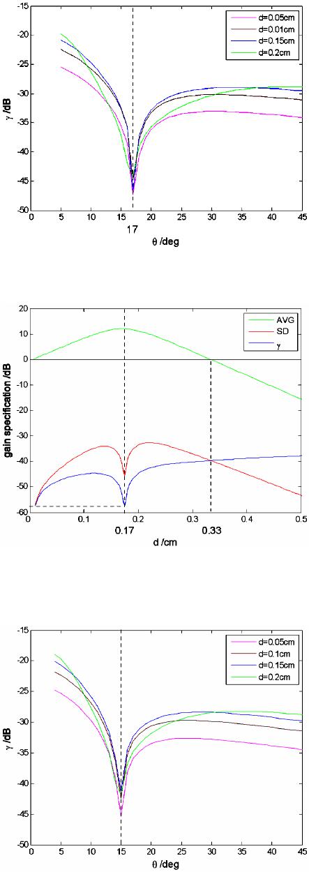 Image Enhancement in Coherent Optical Amplification by Photorefractive Crystals OPEN ACCESS JCC beam: . Computer-generated plots of the non-uniformity of gain versus the average incident angle for different values of d have been presented in Figure 3. The effects of angle on are similar for different values of d. decreases with the increasing , reaches a minimum, then increases and afterwards decreases again. For each value of d, reaches its minimum with a same value of , i.e., . The values of AVG, SD and versus d for the op- timal average incident angle are presented in Figure 4. Within the 0 - 0.33 cm range of d, increas- es with the increasing d, then decreases to a minimum and afterwards increases again. Particularly, the optimal thickness of the crystal , in which case reaches its minimum 0.00016%, is turned out to be 0.17 cm. 3.2. Argon Laser at λ = 514.5 nm The second scenario is that, the operating wavelength of the argon laser used in the first scenario is changed to 514.5 nm, in case the crystal has the parameters of 1 =16.2cm σ − and according to [14]. What’s more, the far-field small divergence angle of the laser beam is turned into . The values of versus angle for different values of d have been presented in Figure 5. The optimal aver- age incident angle , which will guarantee the mini- mum value of regardless of the value of d, is ap- peared to be . Simulation results of AVG, SD and versus d for opt θ are presented in Figure 6. Within the 0-0.43cm range of d, increases with the increasing d, then bas- ically remain unchanged. 3.3. He-Ne Laser at λ = 632.8 nm The last scenario is that, the argon laser used in the first scenario is changed for a He-Ne laser with a cavity length of L = 30 cm at wavelength 632.8 nm, in which case the crystal has the parameters of and . Besides, the far-field small di- vergence angle of the laser beam is turned out to be . The results of with varying angle for different values of d are presented in Figure 7. Note that the fluc- tuation amplitude of is larger than that in the pre- vious two scenarios. The optimal average incident angle is . The values of AVG, SD and versus d for opt θ have been presented in Figure 8. increases with the increasing d, then decreases to a minimum and after- wards increases again. The minimum value of (0.000184%) can be reached with = 0.54 cm. Figure 3. Values of γ versus average incident angle θ for several values of crystal thickness d with λ = 488 nm. Figure 4. Values of AVG, SD and γ versus crystal thickness d for optimal average incident angle with λ = 488 nm. Figure 5. Values of γ versus average incident angle θ for several values of crystal thickness d with λ = 514.5 nm. 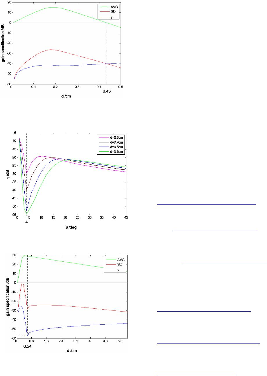 Image Enhancement in Coherent Optical Amplification by Photorefractive Crystals OPEN ACCESS JCC Figure 6. Values of AVG, SD and γ versus crystal thickness d for optimal average incident angle with λ = 514.5 nm. Figure 7. Values of γ versus average incident angle θ for several values of crystal thickness d with λ = 632.8 nm. Figure 8. Values of AVG, SD and γ versus crystal thickness d for optimal average incident angle with λ = 632.8 nm. 4. Conclusion In short, to explore the unevenness of image enhance- ment in coherent optical amplification by photorefractive crystals, a model in view of different spatial frequency in a beam has been built. It has been proved that the factors which impact on the unevenness of image enhancement are: the thickness of photorefractive crystal, the incident angle on each pixel in signal image beam, and the wave- length of incident beams. As an example, the effects of these factors in photorefractive () () 3 Fe 0.04wt%:Ce 0.1wt%:LiNbO crystal have been re- searched through simulation. It turns out that a consi- derable non-uniformity of = 0.00016% can be rea- ched when the wavelength of the incident beam is 488 nm (at , d = 0.17 cm). Acknowledgements The authors thank the National Natural Science Founda- tion of China (No. 61071190, No. 61171158) and the Fundamental Research Funds for the Central Universities of China (No. CDJZR12160010) for support. REFERENCES [1] N. V. Kukhrarev, V. B. Markov, S. G. Odulov, M. S. Soskin and V. L. Vinetskii, “Holographic Storage in Electro-Optic Crystals. I. Steady State”, Ferroelectrics, Vol. 22, No. 1, 1978, pp. 949-953. http://dx.doi.org/10.1080/00150197908239450 [2] M. C. Søren, B. Jensen, J. P. Huignard and P. M. Petersen, “Two-Wave Mixing in a Broad-Area Semiconductor Am- plifier,” Optics Express, Vol. 14, No. 25, 2006, pp. 12373- 12379. http://dx.doi.org/10.1364/OE.14.012373 [3] M. C. Søren, B. Jensen, J. P. Huignard and P. M. Petersen, “Nonlinear Gain Amplification Due to Two-Wave Mix- ing in a Broad-Area Semiconductor Amplifier with Mov- ing Gratings,” Optics Express, Vol. 16, No. 8, 2008, pp. 5565-5571. http://dx.doi.org/10.1364/OE.16.005565 [4] P. Günter and J. P. Huignard, “Photorefractive Materials and Their Applications II,” Springer-Verlag, Berlin, 1989. [5] N. Katyal, Natasha, A. Roy and A. Kapoor, “The Influ- ence of Pump Beam Polarization on the Signal Beam, in TWM in Photorefractive Crystals: Transmission Geome- try,” Optik, Vol. 122, No. 3, 2011, pp. 207-210. http://dx.doi.org/10.1016/j.ijleo.2009.11.028 [6] J. P. Huignard and A. Marrakchi, “Coherent Signal Beam Amplification in Two-Wave Mixing Experiments with Photorefractive Bi12SiO20 Crysta ls,” Optics Communica- tions, Vol. 38, No. 4, 1981, pp. 249-254. http://dx.doi.org/10.1016/0030-4018(81)90392-8 [7] Y. Fainman, E. Klancnik and S. H. Lee, “Optimal Cohe- rent Image Amplification by Two-Wave Coupling in Photorefractive BaTiO3,” Optical Engineering, Vol. 25, No. 2, 1986, pp. 228-234. http://dx.doi.org/10.1117/12.7973810  Image Enhancement in Coherent Optical Amplification by Photorefractive Crystals OPEN ACCESS JCC [8] P. Tayebati and D. Mahgerefteh, “Theory of the photore- fractive effect for Bi12SiO20 and BaTiO3 with shallow traps,” Journal of the Optical Society of America B, Vol. 8, No. 5, 1991, pp. 1053-1064. http://dx.doi.org/10.1364/JOSAB.8.001053 [9] B. G. Peng, F. Chen, Y. Tan and D. Kip, “T wo-Wave Mixing of Ion-Implanted Photorefractive Waveguides in Near-Stoichiometric Fe:LiNbO3 Crystals,” Optics Mate- rials, Vol. 33, No. 6, 2011, pp. 773-776. http://dx.doi.org/10.1016/j.optmat.2010.12.016 [10] Jiabi Chen, “Principle and Application of Laser,” Tongp- ing Han, Beijing, 2004. [11] D. Z. Anderson and R. Saxena, “Theory of Multimode Operation of a Unidirectional Ring Oscillator Having Photorefractive Gain: Weak Field Limit,” Journal of the Optical Society of America B, Vol. 4, No. 2, 1987, pp. 164-176. http://dx.doi.org/10.1364/JOSAB.4.000164 [12] Z. Y. Li, B. Y. Gu and G. Z. Yang, “Slowly Varying Amplitude Approximation Appraised by Transfer-Matrix Approach,” Physical Review B, Vol. 60, No. 15, 1999, pp. 10644-10647. http://dx.doi.org/10.1103/PhysRevB.60.10644 [13] C. H. Ya ng and L. Sun, “Photorefractive Nonliear Optical Materials: LiNbO3 Crystals,” Jiafu Yang, Beijing, 2009. [14] T. K. Yadav, M. K. Maurya and R. A. Yadav, “Effect of Photoconductivity and Oscillation Frequency Shift on the Signal Beam Intensity in Two Beam Coupling in Photo- refractive Materials,” Optik, Vol. 122, No. 18, 2011, pp. 1607-1614. http://dx.doi.org/10.1016/j.ijleo.2010.10.011
|