Paper Menu >>
Journal Menu >>
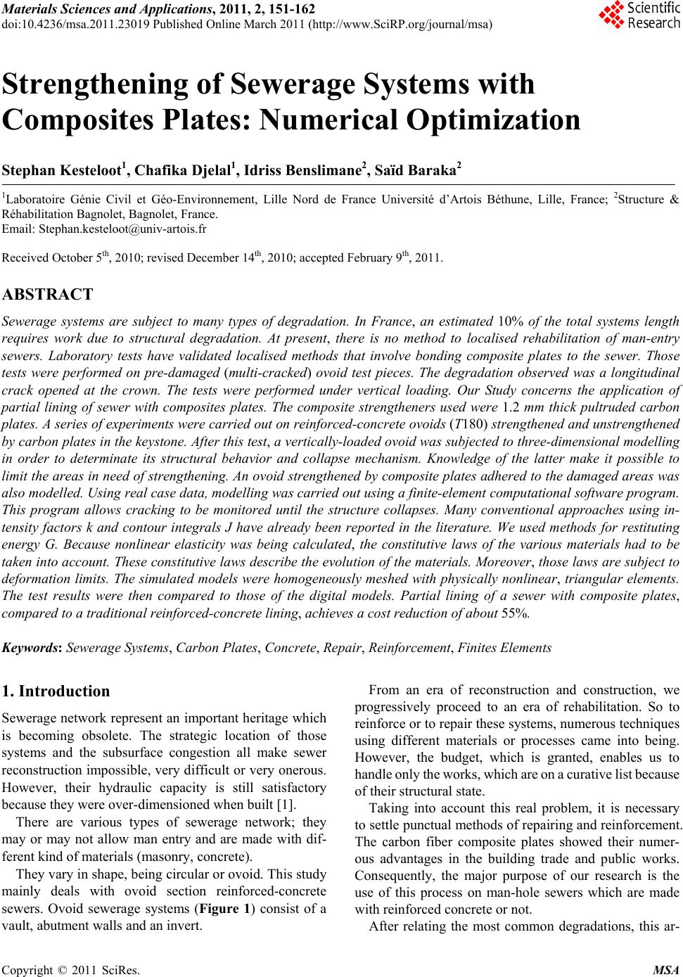 Materials Sciences and Applications, 2011, 2, 151-162 doi:10.4236/msa.2011.23019 Published Online March 2011 (http://www.SciRP.org/journal/msa) Copyright © 2011 SciRes. MSA Strengthening of Sewerage Systems with Composites Plates: Numerical Optimization Stephan Kesteloot1, Chafika Djelal1, Idriss Benslimane2, Saïd Baraka2 1Laboratoire Génie Civil et Géo-Environnement, Lille Nord de France Université d’Artois Béthune, Lille, France; 2Structure & Réhabilitation Bagnolet, Bagnolet, France. Email: Stephan.kesteloot@univ-artois.fr Received October 5th, 2010; revised December 14th, 2010; accepted February 9th, 2011. ABSTRACT Sewerage systems are subject to many types of degradation. In France, an estimated 10% of the total systems length requires work due to structural degradation. At present, there is no method to localised rehabilitation of man-entry sewers. Laboratory tests have validated localised methods that involve bonding composite plates to the sewer. Those tests were performed on pre-damaged (multi-cracked) ovoid test pieces. The degradation observed was a longitudinal crack opened at the crown. The tests were performed under vertical loading. Our Study concerns the application of partial lining of sewer with composites plates. The composite strengtheners used were 1.2 mm thick pultruded carbon plates. A series of experiments were carried out on reinforced-concrete ovoids (T180) strengthened and unstrengthened by carbon plates in the keystone. After this test, a vertically-loaded ovoid was subjected to three-dimensional modelling in order to determinate its structural behavior and collapse mechanism. Knowledge of the latter make it possible to limit the area s in need of stren gthening. An ovoid strengthened by com posite plates adhered to the damaged a reas was also modelled. Using real case data, modelling was carried ou t using a finite-element computationa l software prog ram. This program allows cracking to be monitored until the structure collapses. Many conventional approaches using in- tensity factors k and contour integrals J have already been reported in the literature. We used methods for restituting energy G. Because nonlinear elasticity was being calculated, the constitutive laws of the various materials had to be taken into account. Th ese constitutive laws describe the evolution of the materials. Moreover, those laws are subject to deformation limits. The simulated models were homogeneously meshed with physically nonlinear, triangular elements. The test results were then compared to those of the digital models. Partial lining of a sewer with composite plates, compared to a traditional reinforced-concrete lining, achieves a cost reduction of about 55%. Keywords: Sew e rage Sy st em s, Carbon Plates, Concrete, Repair, Reinforcement, Finites Elements 1. Introduction Sewerage network represent an important heritage which is becoming obsolete. The strategic location of those systems and the subsurface congestion all make sewer reconstruction impossible, very difficult or very onerous. However, their hydraulic capacity is still satisfactory because they were over-dimensioned when built [1]. There are various types of sewerage network; they may or may not allow man entry and are made with dif- ferent kind of materials (masonry, concrete). They vary in shape, being circular or ovoid. This study mainly deals with ovoid section reinforced-concrete sewers. Ovoid sewerage systems (Figure 1) consist of a vault, abutment walls and an invert. From an era of reconstruction and construction, we progressively proceed to an era of rehabilitation. So to reinforce or to repair these systems, numerous techniques using different materials or processes came into being. However, the budget, which is granted, enables us to handle only the works, which are on a c urative list because of their structural state. Taking into account this real problem, it is necessary to settle punctual methods of repairing and reinforcement. The carbon fiber composite plates showed their numer- ous advantages in the building trade and public works. Consequently, the major purpose of our research is the use of this process on man-hole sewers which are made with reinforced concrete or not. After relating the most common degradations, this ar- 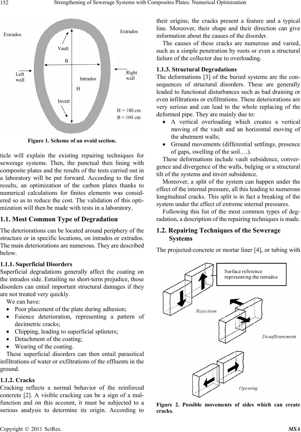 Strengthening of Sewerage Systems with Composites Plates: Numerical Opti mi zation Copyright © 2011 SciRes. MSA 152 Figure 1. Scheme of an ovoid section. ticle will explain the existing repairing techniques for sewerage systems. Then, the punctual then lining with composite plates and the results of the tests carried out in a laboratory will be put forward. According to the first results, an optimization of the carbon plates thanks to numerical calculations for finites elements was consid- ered so as to reduce the cost. The validation of this opti- mization will then be made with tests in a laboratory. 1.1. Most Common Type of Degradation The deteriorations can be located around periphery of the structure or in specific locations, on intrados or extrados. The m ain deter ioratio ns are num erous. T hey are descri bed below. 1.1.1. Superficial Disorders Superficial degradations generally affect the coating on the intrados side. Entailing no sh ort-term prejudice, those disorders can entail important structural damages if they are not treated very q uic kl y . We can have: Poor placement of the plate during adhesion; Faience deterioration, representing a pattern of decimetric cracks; Chipping, leading to superficial splinters; Detachment of the coating; Wearing of the coating. These superficial disorders can then entail parasitical infiltrations of water or exfiltrations of the effluents in the ground. 1.1.2. Cracks Cracking reflects a normal behavior of the reinforced concrete [2]. A visible cracking can be a sign of a mal- function and on this account, it must be subjected to a serious analysis to determine its origin. According to their origins, the cracks present a feature and a typical line. Moreover, their shape and their direction can give information about the causes of the disorder. The causes of these cracks are numerous and varied, such as a simple penetration by roots or even a structural failure of the collector due to overloading. 1.1.3. Structural Degradations The deformations [3] of the buried systems are the con- sequences of structural disorders. These are generally leaded to functional disturbances such as bad draining or even infiltrations or exfiltrations. These deteriorations are very serious and can lead to the whole replacing of the deformed pipe. They are mainly due to: A vertical overloading which creates a vertical moving of the vault and an horizontal moving of the abutment walls; Ground movements (differential settlings, presence of gaps, swelling of the soil….). These deformations include vault subsidence, conver- gence and divergence of the walls, bulging or a structural tilt of the systems and invert su bsidence. Moreover, a split of the system can happen under the effect of the internal pressure, all this leading to numerous longitudinal crack s. This split is in fact a breaking of the system under the effect of extreme internal pressures. Following this list of the most common types of deg- radation, a description of the repairing tec hniques is m ade. 1.2. Repairing Techniques of the Sewerage Systems The projected-concrete or mortar liner [4 ], or tub ing with Figure 2. Possible movements of sides which can create cracks. 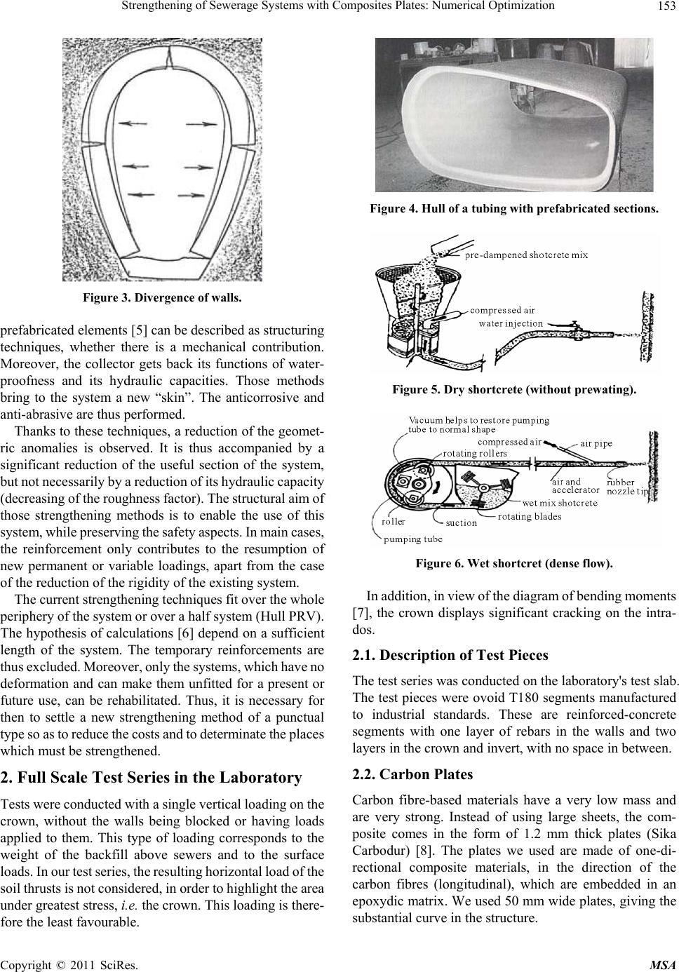 Strengthening of Sewerage Systems with Composites Pla t e s: Numerical Optimiz at ion Copyright © 2011 SciRes. MSA 153 Figure 3. Divergence of walls. prefabricated elements [5] can be described as structuring techniques, whether there is a mechanical contribution. Moreover, the collector gets back its functions of water- proofness and its hydraulic capacities. Those methods bring to the system a new “skin”. The anticorrosive and anti-abrasive are thus performed. Thanks to these techniques, a reduction of the geomet- ric anomalies is observed. It is thus accompanied by a significant reduction of the useful section of the system, but not necessari ly by a reduct ion of i ts hyd raulic capacity (decreasing of the roughness factor). The structural aim of those strengthening methods is to enable the use of this system, while preserving the safety aspects. In main cases, the reinforcement only contributes to the resumption of new permanent or variable loadings, apart from the case of the reduction of the rigidity of the existing system. The current str engt heni ng t ec hni que s fi t o ver t he wh ole periphe ry o f th e s yst em or over a hal f sy st e m (Hul l PRV ). The hypothesis of calculations [6] depend on a sufficient length of the system. The temporary reinforcements are thus exclude d. Moreover, only the systems, which ha ve no deformation and can make them unfitted for a present or future use, can be rehabilitated. Thus, it is necessary for then to settle a new strengthening method of a punctual type so as to re duce the costs and t o determinate the places which must be strengthened. 2. Full Scale Test Series in the Laboratory Tests were co nduct ed wit h a s ing le verti cal l oadi ng on t he crown, without the walls being blocked or having loads applied to them. This type of loading corresponds to the weight of the backfill above sewers and to the surface loads. In our test series, the resulting horizontal load of the soil thrusts is not considered, in order to highlight the area under greatest stress, i.e. the crown. This loading is there- fore the least favourable. Figure 4. Hull of a tubing with prefabricated sections. Figure 5. Dry shortcrete (without prewating). Figure 6. Wet shortcret (dense flow). In addition, in view of the diagram of bending moments [7], the crown displays significant cracking on the intra- dos. 2.1. Description of Test Pieces The test series was conducted on the laboratory's test slab. The test pieces were ovoid T180 segments manufactured to industrial standards. These are reinforced-concrete segments with one layer of rebars in the walls and two layers in the crown and inv ert, with no space in between. 2.2. Carbon Plates Carbon fibre-based materials have a very low mass and are very strong. Instead of using large sheets, the com- posite comes in the form of 1.2 mm thick plates (Sika Carbodur) [8]. The plates we used are made of one-di- rectional composite materials, in the direction of the carbon fibres (longitudinal), which are embedded in an epoxydic matrix. We used 50 mm wide plates, giving the substantial curve in the structure. 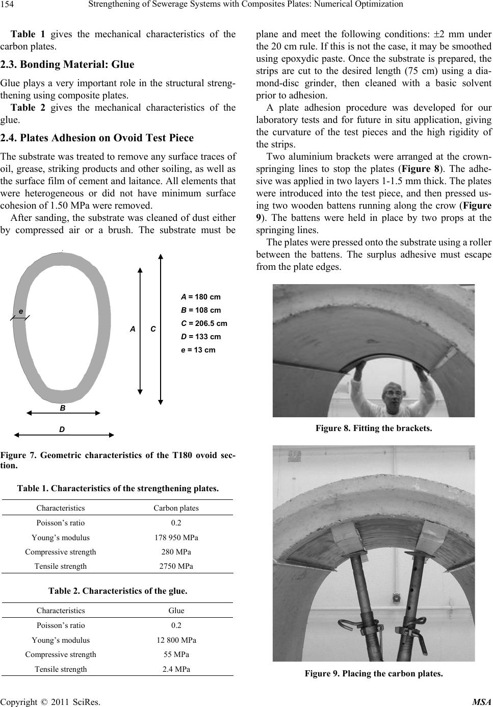 Strengthening of Sewerage Systems with Composites Plates: Numerical Opti mi zation Copyright © 2011 SciRes. MSA 154 Table 1 gives the mechanical characteristics of the carbon plates. 2.3. Bonding Material: Glue Glue plays a very important role in the structural streng- thening using composite plates. Table 2 gives the mechanical characteristics of the glue. 2.4. Plates Adhesion on Ovoid Test Piece The substrate was treated to remove any surface traces of oil, grease, striking products and other soiling, as well as the surface film of cement and laitance. All elements that were heterogeneous or did not have minimum surface cohesio n o f 1.50 MPa we re removed. After sanding, the substrate was cleaned of dust either by compressed air or a brush. The substrate must be A = 180 cm B = 108 cm C = 206.5 cm D = 133 cm e = 13 cm e A C D B Figure 7. Geometric characteristics of the T180 ovoid sec- tion. Table 1. Characteristics of the strengthening plates. Characteristics Carbon plates Poisson’s ratio 0.2 Young’s modulus 178 950 MPa Compressive strength 280 MPa Tensile strength 2750 MPa Table 2. Characteristics of the glue. Characteristics Glue Poisson’s ratio 0.2 Young’s modulus 12 800 MPa Compressive strength 55 MPa Tensile strength 2.4 MPa plane and meet the following conditions: 2 mm under the 20 cm rule. If this is not the case, it may be smoothed using epoxydic paste. Once the substrate is prepared, the strips are cut to the desired length (75 cm) using a dia- mond-disc grinder, then cleaned with a basic solvent prior to adhesion. A plate adhesion procedure was developed for our laboratory tests and for future in situ application, giving the curvature of the test pieces and the high rigidity of the strips. Two aluminium brackets were arranged at the crown- springing lines to stop the plates (Figure 8). The adhe- sive was applied in two layers 1- 1.5 mm thick . The plates were introduced into the test piece, and then pressed us- ing two wooden battens running along the crow (Figure 9). The battens were held in place by two props at the springing lines. The plates were pressed onto the substrate using a roller between the battens. The surplus adhesive must escape from the plate edges. Figure 8. Fitting the brackets. Figure 9. Placing the carbon plates.  Strengthening of Sewerage Systems with Composites Pla t e s: Numerical Optimiz at ion Copyright © 2011 SciRes. MSA 155 Before testing, several gaps between the plates and substrates were observed, mainly between the batten and the plate stop. When the reinforced ovoid segments rup- tured, collapse occurred at the gaps. 2.5. Test Procedure This test procedure h ighlighted the provision of localised reinforcement in the event of vertical overload, with the presence of gaps at the wall-soil interface. In order to spread the load uniformly over the crown, a sand-filled wooden container was made. The load was therefore applied uniformly without slippage on the crown. The load application surface was 0.45 m wide by 1.20 m long, in order to focus the loading on the crown. At ground level, in view of the sewer's design, a fine mortar low thickness was placed under the test piece to absorb ground and invert irregularities. The INSTRON press we used has a digitally-con- trolled hydraulic jack. The load was measured using a force sensor of 250 kN static capacity. During testing, we measured crown sagging and wall displacement in order to verify the structure’s symmetry. Crown displacements were measured using LVDT sensors connected to a data- acquisition unit. The purpose of the tests was to define the mechanisms of deformation and collapse of ovoid segments subjected to vertical loading. The vertical overload was generated without any lateral stops on the test piece, to make it as unfavourable as possible with regard to the tensile stresses in the crown. In situ sewers, whose soil/structure interface does not have decompression voids, partly re- distribute the stresses to the soil. For each test, crown displacement and divergence of the walls (outward displacement of each wall) were mea- sured. In addition, extensiometric gauges were placed in Figure 10. Test set-up. stressed areas of the test piece. These areas were identi- fied during linear numerical calculations, by taking ac- count of the permissible tensile stress of the concrete. The test results yielded: The deformation mechanism of the test pieces, with the gradual appearance of cracks; The behavior of the test pieces during loading; The rupture load. The carbon plates were arranged edge to edge on the crown. The surface to be strengthened was defined by a numerical study [9] performed using the commercial URUS structural design software program [10]. The se- lected area represents 0.75 m2 to be reinforced per meter length of sewer. 2.6. Test Series Results For our test series, two non-reinforced ovoid segments (controls) and two reinforced segments were subjected to an axial vertical loading. It is useful to take account of the onset of the first cracks in order to assess the in-service behavior of the structure. Two ovoid segments were tested in each case, and high reproducibility of results was observed. Results are therefore given for one test piece only. Figure 12 shows the behaviour of the test pieces under vertical loading, at the speed of 1 mm/min. In terms of elasticity, the test pieces behave identically until onset of the first crack (95 kN) in the control-piece crown. Then we observe cracks developing in the extrados of the wall midpoints, in the crown, and in the intrados of the invert-wall join. With the control pieces, the c urve changes after onset of the first crack, whereas with the reinforced pieces the initial rise continues steadily until the first detachment occurs. This is caused by: Poor placement of the plate during adhesion; The thrust into the void to which the plates are sub- ject. Figure 11. Test slab.  Strengthening of Sewerage Systems with Composites Plates: Numerical Opti mi zation Copyright © 2011 SciRes. MSA 156 Table 3. Results of full-scale test. Test Max load [kN] Load at onset of first crack Crown sag [mm]Left-wall sag [mm] Right-wall sag [mm] Control ovoid 160 95 kN (crown), 120 kN (invert), 125 kN (right-midpoint) 6.15 9.42 5.49 Reinforced ovoid pieces 250 150 kN (invert) and 240 kN (right-w a ll midpoint) 7.79 5.19 0.83 Figure 12. Test piece behavior. The rupture load for the reinforced piece is 250 kN and for the control piece 160 kN, representing a 55% gain. However a more fragile behaviour is observed. In addi- tion, we observed: A redistribution of the stresses towards the invert (obtained by gauges and modelling), but also out- wards at the wall midpoints; An increase in the load at first-crack onset of nearly 60% over the load at first-crack onset in the unreinforced test pieces; First-crack onset in the invert under a load nearly 15% greater than that at which the first crack ap- peared in the unreinforced test pieces. This delay in cracking and the r edistribution of stresses towards the invert are essential parameters. The forces are transferred from the structure to the plates via the adhe- sive. Moreover, traditional sizing of sewerage structures only takes account of the service range, which validates use of this p rocess. The stresses are measured on the slides using strain gages. The stress measured in the plate was 76.90 MPa, i.e. a stress value of 2.7%. Moreover, we had a relative elon- gation of 1‰. This elongation is well below the permis- sible value for carbon plates. All the test pieces (reinforced and non-reinforced) ruptured identically. The cracks continued to open and progress, reaching maximum crack openning in the crown of approx imately 7 mm. As Figure 13 shows, co l- lapse of the crown occurred at 45˚ relative to the soil plane, at the springing line. The crack spread outwards from the intrados. Placement of the reinforcements in the crown altered the collapse mechanism of the ovoid segments. Rupture took the form of plate detachment from the crown con- crete. The plates did not peel off due to the geometry of the structure. The plates gradually detached from the substrate where adhesion was not total. However, ruptu re occurred in the crown due to concrete decohesion (Figure 14). Figure 13. Rupture of a test piece under vertical loading. Figure 14. Strip detachment before concrete.  Strengthening of Sewerage Systems with Composites Pla t e s: Numerical Optimiz at ion Copyright © 2011 SciRes. MSA 157 Once the plates detached from the crown, rupture was immediate. Complete collapse of the structure occurred in the same way in the unreinforced structures. 3. Numerical Study—Non Linear Finite Element Analysis Several analytical methods [11,12] have been developed to predict the bending behaviour of elements reinforced with glued-on composites. In view of the limits imposed by these numerical methods, and particularly on account of the complex distribution of stresses in the film of glue, it seemed necessary to use a more precise method. 3.1. Description of the Sofware Numerous studies of numerical methods [13,14] have already been carried out in recent years in the field of concrete. With the software currently available, it is pos- sible to represent the state of the structures under load- ing. It is proposed that th e question shou ld be stud ied again in the framework of fracture mechanics as the classical approaches in the form of stress intensity factors k [15] and contour integrals J [16] have not been fruitful. New software has recently been developed using energy release rate methods [17], whereby it is possible to perform the calculations for concrete. The finite-element software URUS Version 9 [10] will be used in the context of this study. The finite elements used are triangular or quad- rangular plate elements. Only the membrane effects will be taken into account (in plane stress conditions). During the simulations, solution in non-linear elastic conditions will be used. The non-linear prob lem arises because of the constitu- tive law of the concrete. They are also limited in relation to strain. The URUS software possesses a library of pre- defined laws. By way of example, there is the “poly-line” constitutive law that corresponds to portions of linear segments linked to one another, or the “exponential” type law. The limits are prescribed in terms of strain. 3.2. Model Used The chosen model was uniformly meshed with non-linear physically triangular plates. The mesh pitch was refined during the simulations. The chosen pitch was 0.1 m. The materials of the strengthened ovoid sections were assem- bled by bonding the elements with nodes whose degrees of freedom remained unrestricted. Boundary conditions were defined by locking the invert on the extrados side to form a 60˚ angle. To represent the structure symmetry, nil horizontal displacement was applied to the nodes on the axis of symmetry. Figures 15 and 16 show the chosen model. Figure 15. Face model mesh. Figure 16. 3D model mesh. The computation was then run until the iterative pro- cess no longer conver ged. 3.3. Law of Behaviour 3.3.1. Concrete The characteristics of the concrete of ovoid sections were obtained from laboratory tests. Holes were drilled in an un-strengthened ovoid section, and then single compres- sion tests and Young’s modulus measurement tests were conducted. Table 4 gives the characteristics of the con- crete. The general form [18] of uni-axial laws of behavior,  Strengthening of Sewerage Systems with Composites Plates: Numerical Opti mi zation Copyright © 2011 SciRes. MSA 158 Table 4. Characteristics of concrete. Characteristics Concrete Substrate Poisson’s ratio 0.2 Young’s modulus 15 400 MPa Compressive strength 30 MPa Tensile strength 2.4 MPa used for the continuous media applicable to concrete, is given in Figure 17. 3.3.2. S tr engthening: Carbon Plate s Because the final characteristics of composite materials depend on those of the fibers, Meier [19] chose various criteria for a comparative study. This study found that carbon fiber is best suited to structural strengthening. The law of behaviour chosen for the carbon plates is given in Figure 18. 3.3.3. Bonding Material: Glue Deuring [20] found that the behavior of a glue film de- composes in two areas: one elastic and nearly linear, the other pl ast ic. The laws of behaviour adopted for the glue are expo- nential. This type of law makes it possible to reproduce the linear elastic area, then the plastic area. The law of behavior of the glue is outlined in Figure 19. 3.4. Results of the Numerical Computations An un-strengthened ovoid section was numerically com- puted to obtain its collapse mechanisms and define the areas in need of strengthening. The carbon plates were positioned transversally and continuously on the vault. After several numerical simulations, [21] the chosen trans- versal surface corresponded t o a width of 0.75 metres. The results of this strengthening method are described in the next paragraph. Once the transversal strengthening area was determined, a longitudinal optimisation was perfor- med in order to limit the number of plates (inter-plate spacing). 3.4.1. Compari s o n between Un- S t rengthe ne d Ovoid Sections The un-strengthened ovoid section was subjected to a loading equating to silty soil backfill 2 meters in height. During modelling, a series of load increments was applied to obtain its full collaps e. The manufacturer of the ovoid sections certified their strength to be 138 kN. We obtained a rupture load of 157.5 kN, giving a safety coefficient of 1.15 compared to the manufacture r's value. The behavior of the un- strengthened ovoid sectio n is give n i n Figure 12. During the numerical Figure 17. Constitutive law of concrete. Figure 18. Constitutive law of composite. Figure 19. Constitutive law of glue.  Strengthening of Sewerage Systems with Composites Pla t e s: Numerical Optimiz at ion Copyright © 2011 SciRes. MSA 159 simulation, the damaged areas were verified in relation to the line of the bending-moment diagram [17]. The distribution of the tensiles areas is identical be- tween model and experimentation. In order to validate our laws of behavior of the carbon plates and the con- crete, and our model, a comparison is carried out be- tween the behavior of the model and the experimental tests. 3.4.2. Comparison between St re ngthened Ovoid Sections With the strengthened ovoid section, collapse occurred at the fifth loading step, 262.5 kN. A 60% load gain over the un-strengthened ovoid section was thus observed. In ad- dition, cracking was retarded. In the reference ovoid sec- tion, the first crack appeared at 95 kN in the vault, whereas it appeared at 160 kN in the invert of the ovoid section continuously strengthened by the positioning of the plates. Figure 21 shows the stresses present at collapse of the continuously strengthened T180 ovoid section. The stre- sses in the concrete were low, because the glue transmit- ted the forces into the plates. The behavior of the strengthened ovoid section is identical to that of the un-strengthened section in terms of concrete elasticity, i.e. until the appearance of the first crack, in the un-strengthened ovoid section. The load-sag curve in Figure 22 shows the behavior of a continuously strengthened ovoid section. Our findings show that this type of strengthening is well suited to ovoid sewers, despite the considerable curve in the vault. Having obtained these first results, we optimised the area in need of strengthening in order to limit the cost of in-situ application. 3.4.3. Optimization of the Strengthening Plates Different numerical strengthening cases were tested to determine the smallest possible area in need of strength- ening. Figure 20. Comparison between un-strengthening ovoid sec- tions. Figure 21. Collapse mechanism. Mapping of the Main Stresses of the continuously strengthening ovoid section. Figure 22. Comparison between strengthening ovoid sec- tions. First, one out of two plates was applied. The numerical results showed that it was possible to reduce the area in need of strengthening. The area finally chosen was one- third of the initial area. The chosen arrangement was 150 mm wide plates separated by a 300 mm gap. The parameters determining the minimal strengthening area were as follows: Retardation of the first crack until 138 kN, the permissible load of a T180 ovoid section supplied by the manufacturer; Load gain greater than 30% of the reference ovoid-section load. Figure 23 gives the mapping of the main stresses for the strengthened ovoid section with inter-plate spacing. The load-sag curve of the s t r engthened ovoi d w ith spa-  Strengthening of Sewerage Systems with Composites Plates: Numerical Opti mi zation Copyright © 2011 SciRes. MSA 160 Figure 23. Collapse Mechanism - Mapping of the main Stresses of the continuously strengthening ovoid section. cing (Figure 12) indicates a slight change in elasticity around 105 kN. However, the significant change in rigid- ity occurs at 157.5 kN, the load at which the first crack appears in the vault between the carbon plates. The rup- ture load is 210 kN, a 35% gain over the un-strengthen ed ovoid section. 3.4.4. C om parison an d Conclusion The differences in behavior between the various models are shown in Figur e 2 4. The three load-sag curves are identical until 95 kN, when the first crack is observed in the un-strengthened ovoid section. The comparison between the behavior of the two types of strengthened area shows a reduction in the rigidity of the stre ngthene d ovoid secti on with s pacing at about 105 kN. However, the two sections behave similarly until 157.5 kN. Above this loading there is a greater difference in rigidity, due to the appearance of the cracks between the plates. As for the reference ovoid section, the load-sag curve shows two main domains: the elastic domain up to 95 kN, then the plastic domain with appearance of cracks through to structural collapse. Following these numerical computations, an extensive series of experiments was conducted to compare the ob- tained results to the numerical computations. Two un- strengthened ovoid sections were tested to verify the law of behavior applied to concrete and to d etermine the col- lapse mechanism. Then two ovoid sections continuously strengthened in the vault were loaded to collapse. Appli- cation of composite plates on the vault achieves a 60% load gain and retards cracking. Figure 24. Comparison of the numerical curves. For this paper, only the tests on strengthened ovoid sections with inter-plate spacing were compared to the numerical simulations. 4. Comparison of Test and Computations The ovoid sections were vertically loaded. The load was applied to the vault, and eq uated to the weight of backfill soil above the sewers. The jack load was transmitted to the structure by means of a wooden shuttering filled with sand, to uniformly distribute the load on the vault. (Fig- ure 25) The resultant horizo ntal thru st of the soil was not considered, in order to highlight the area under greatest stress, i.e. the vault. Two T180 ovoid section s with inter-plate spacing were tested. The results were similar, so only one of the tests was used for this paper. Cracks appeared at 168 kN, and first developed be- tween the carbon plates. Cracks also appeared in the in- vert inside and at the midpoint of the walls on the outside. Gradual opening of the cracks from the inside towards the outside was o bserved. These cracks caused the struc- ture to collapse. (Figure 26) Collapse occurred between the extreme point of loading and the edge of the strengthened area. We obtained the same collapse mechanism for the un-strengthened and continuously-strengthened sections. The maximum recorded loading was 192 kN. During testing, the plates detached from the substrate. However, detachm ent was caused by decohe sion in the subst rate and not by rupture of the glue bond. Comparison of numerical simulation and experiment series; Figure 27 gives the curves o btained by modelling and the experiment series. In the elastic domain, behavior were similar. The be- havior of the tested ovoid section showed quasi-elastic behavior u p to 160 kN. C racks then ap peared between t he plates, showing the plastic behaviour of the section. The numerical cu rve showed greater structural rigidity in the plastic domain. The difference in behaviour was  Strengthening of Sewerage Systems with Composites Pla t e s: Numerical Optimiz at ion Copyright © 2011 SciRes. MSA 161 Figure 25. Loading. Figure 26. Structural collapse. Figure 27. Comparison on the experimental and numerical curves. caused by the difficulty of applying the plates to the curved surface. During testing, spaces were noted be- tween the plates and the substrate. These spaces caused a loss of structural ri g i d ity. 5. Conclusions The appl ication of ca rbon plates to sewer vaults achieves a 60% gain in rupture loads, and retards the appearance of the first cracks. The gaps in our understanding of ovoid- section behavior were filled by finite element modelling. However, because our computations were based on per- fect adhesion, we obtained slightly different behavior when cracks appeared. For the application of carbon plates in the next stage of our experiment series, the strengthening plates will be placed by inflating a balloon. Use of this strengthening method for sewer renovation reduces job cost by 60%. In addition, the section of the sewer is not r educed. During loadin g, inte r-plat e spaci ng m akes it possi ble to visualise the concrete cracking in the vault. A series of tests was carried out on concrete sample reinforced by FRP in various environments. During join- ing in saturated environment, the results of the tests showed that it was necessary to apply a safety coefficient related to the problem of adherence to wet facing [21]. Our project partner companies decided to validate this process by a field test. The site was located in Dépar- tement du Val de Marne, in the municipality of Saint Maur des Fossés, on Quai du Port au Fouarre. The struc- ture was a drainage sewer (2.30 m high and 1.30 m wide). After the work, the area rehabilitated by the process will undergo regular inspections to monitor the behavior and Figure 28. Field test.  Strengthening of Sewerage Systems with Composites Plates: Numerical Opti mi zation Copyright © 2011 SciRes. MSA 162 durability of the materials. Twenty months after adhesion was completed, no deterioration in the reinforcement (plate or adhesive) was observed. Moreover, no detach- ment was observed. Routine inspections were held to monitor the performance of the reinforcement. 6. Acknowledgements This study was undertaken thanks to the financial supp ort of the Companies Structure & Réhabilitation, Sika and valentin Environnement et Travaux Publics. REFERENCES [1] Projet National RERAU, “Restructuration des Collecteurs Visitables,” Tome 1, Editions Lavoisier, France, 2002. [2] IREX, “Comportement des Ouvrages Dans le Temps,” Enquête Auprès des Maîtres d’Ouvrage, n 23, France, Octobre 1994. [3] “Cahiers des Pathologies des Ouvrages d’Assainissement Visitables,” Equipement Ile de France, France. [4] “Manuel de Recommandations Techniques, Inspection Telévisé et Réhabilitation des Réseaux d’Assainissement,” Ministère de l’Equipement, du Logement et des Transports, Direction de l’Architecture et de l’Urbanisme, France, Septembre 1991. [5] “Documents Techniques,” Entreprise SADE, France. [6] “Restructuration des Collecteurs Visitables, Conséquences et Remède”s, Guide Technique, Tome 2, Projet National RERAU, Editions Lavoisier, France, 2004. [7] A. Guerrin and G. Daniel, “Traité de béton armé— Ouvrages enterrés,” Tome 8, Editions Dunod, Paris, 1969. [8] E. David, “Comportement Mécanique de Poutres en Béton Armé Renforcées ou Réparées par Collage de Matériaux composites—Etude Expérimentale et Modélisation,” Thèse de Doctorat, Université d’Artois, Béthune, 1999. [9] S. Kesteloot, C. Djelal, S. Baraka and I. Benslimane, “Modelling of Sewerage Systems Strengthening with Composites Plates,” Construction and Building Materials, Vol. 20, 2006, pp.158-168. doi:10.1016/j.conbuildmat.2005.01.016 [10] URUS Version 9 “Logiciel de Calculs de Structures par Éléments Finis,”@bd soft, 2004. [11] B. Täljsten, “Plate Bonding, Strengthening of Concrete Structures with Epoxy Bonded Plates of Steel or Fiber Reinforced Plastics,” Doctoral Thesis, Lulea University of Technology, Lulea, 1994. [12] T. C. Triantafillou, “Shear Strengthening of Reinforced Concrete Beams Using Epoxy Bonded FRP Composite,” ACI Structural Journal, Vol. 46, No. 1, 1995, pp. 107-115. [13] M. Arduini, A. di Tommaso and O. Manfroni, “Fracture Mechanics of Concrete Beams Bonded with Composite Plates,” In: L. Taerwe, Ed., Non-Metallic (FRP) Rein- forcement for Concrete Structures, Rilem, London, 1995, pp. 485-491. [14] T. C. Triantafillou, N. Deskovic and M. Deuring, “Streng- thening of Concrete Structures with Prestressed Fiber Reinforced Plastic Sheets,” ACI Structural Journal, Vol. 89, 1989, pp. 235-244. [15] G. R. Irwin, “Analysis of Stresses and Strains near the End of a Crack Traversing a Plate,” Journal of Applied Mechanics-Transactions of the ASME, Vol. E24, 1957, pp. 351-369. [16] J. R. Rice, “A Path Independent Integral and Approximate Analysis of Strain Concentration by Notches and Cracks,” Journal Applied Mechanics, Vol. 35, 1968, pp. 379-386. [17] J. Lemaître and J. L. Chaboche, “Mécanique des Matériaux Solides,” Editions Dunod, Paris, 1985. [18] J. Mazars, “Méca nismes Physiques de Rupture et Modèles de Comportement du Béton Hydraulique in Le Béton Hydraulique,” Presse de l’Ecole Nationale des Ponts et Chaussées, Paris, 1982. [19] U. Meier, “Strengthening of Structures Using Carbon Fibre/Epoxy Composites,” Constructions and Building Materials, Vol. 9, No. 6, 1995, pp. 341-351. doi:10.1016/0950-0618(95)00071-2 [20] M. Deuring., “Verstärken von Stahlbeton mit Gespannten Faserverbundwerkstoffen”, Doctoral Thesis, Eidgenös- sischen Technischen Hochschule, Zürich, 1993. [21] S. Kesteloot, “Réhabilitation des Ouvrages d’Assainissement par Matériaux Composites: Etude expérimentale et Dimensionnement par Calculs Numériques”, Thèse de Doctorat, Université d’Artois, Béthune, 2005. |