 Open Journal of Synthesis Theory and Applications, 2014, 3, 5-13 Published Online January 2014 (http://www.scirp.org/journal/ojsta) http://dx.doi.org/10.4236/ojsta.2014.31002 OPEN ACCESS OJSTA Doped Amorphous Carbon Films Prepared by Liquid Phase Electrodeposition Canyan Che, Yang Li, Guifeng Zhang*, Dewei Deng Key Laboratory for Materials Modification by Laser, Ion and Electron Beams, Ministry of Education, School of Materials Science and Engineering, Dalian University of Technology, Dalian, China Email: *gfzhang@dlut.edu.cn Received September 22, 2013; revised October 30, 2013; accepted November 21, 2013 Copyright © 2014 Canyan Che et al. This is an open access article distributed under the Creative Commons Attribution License, which permits unrestricted use, distribution, and reproduction in any medium, provided the original work is properly cited. In accor- dance of the Creative Commons Attribution License all Copyrights © 2014 are reserved for SCIRP and the owner of the intellectual property Canyan Che et al. All Copyright © 2014 are guarded by law and by SCIRP as a guardian. ABSTRACT It has theoretical significance and practical value to synthetize and modify amorphous carbon films by liquid electro-deposition technique due to its low cost, simple equipment, and better operability in uniform deposition of the films with large -area and complex shape work pieces. This article introduces the research situation of the carbon films prepared by liquid phase electrochemical deposition according to the applied voltage, discusses the influence of experimental parameters on the film properties, and describes possible reaction mechanisms. It summarizes the research progress of amorphous carbon films doped with metal and nonmetals. Finally, existing problems have been demonstrated and suggestions on research hotspots in the future are given. KEYWORDS Liquid Electrodeposition; Doping; Carbon Films 1. Introduction Amorphous carbon films have an extensive application prosperity in the mechanical, electronic, chemical, mili- tary and aerospace fields due to their low friction coeffi- cient, good wear resistance, chemical inertness, and high transmittance in a wide range from infrared to ultraviolet. Recently, various physical vapor deposition (PVD) and chemical vapor deposition (CVD) methods, including ion beam deposition, pulsed laser deposition, and plasma enhanced CVD, etc., are used to prepare t he films. How- ever, the deficiencies of these techniques are more com- plex equipment, higher cost, and more difficult in depo- sition uniform films with large -area and irregular surface [1]. Maissel et al. [2] pointed out that the film materials prepared in the gas phase can be also obtained from elec- trochemical deposition in the liquid phase, and vice versa. Hydrogenated carbon films were successfully synthe- sized by Na mb [3] in 1992 from electrochemical deposi- tion technique. Generally, using a high voltage, the films were deposited on substrate as cathode and graphite or Pt served as anode [4,5]. The report has attracted much at- tention in view of the facts of low-cost, random choice of substrates an d car bon sources, and easy doping. 2. Amorphous Carbon Films Prepared by Cathodic Deposition Mode 2.1. Application of High-Voltage (1000 - 3000 V) Some experiments have proved that hydrogenated amor- phous carbon films with obvious characteristics of di- amond structure can be prepared using liquid–phase de- position under atmospheric pressure and low temperature. Figure 1 shows SEM photographs of the films deposited from organic solvents of methanol, ethanol, and iso- propyl alcohol. These organic solvents possesses a lower electrical conductivity and hence a higher voltage in the range of 1000 - 3000 V should be applied between two electrodes. All the same, the deposition rate is very low. Two electrodes can be regarded as idea parallel plate capacitor. Solution with a dielectric constant ε is pola- rized under the action of external electric field. Induced charges created on the electrodes and the density (also *Corresponding a uthor.  C. Y. CHE ET AL. OPEN ACCESS OJSTA (a) (b) (c) Figure 1. SEM photographs of the films depositd from var- ious organic solvents of (a) methanol [6]; (b) ethanol [7], and (c) is opropyl alcohol [8] at 1000 V. known as the polarization ability) is determined by the formula , where is constant and E electric field intensity. Obviously, under the same depo- sition conditions P depends only on the dielectric con- stants. It is therefore necessary to select organic solutions with high dielectric constant [9]. Carbon sources fre- quently used contain methanol [10], alcohol [11,12], methyl cyanide, DMF, DMSO [13,14], and so on. The growth mechanism of carbon membrane can be briefly described as follows: 1) the center of positive and nega- tive charges in polarized molecules is non-coincidence and electronic distribution tends to the polar functions. Under the action of a high external electric field, the charges are more away from the center, molecules will be induced polarization; 2) positively and negatively charged polar functional groups generate in the solution by interrupting weak chemical bonds; 3) meanwhile, the surface of the electrodes is activated, and the charged particles move to the electrode and are captured on the activity locations; 4) the positively charged groups are captured and obtains the extra electron on the cathode, and then dehydrogenation and deoxidization reactions occur to form C-C bonds [15]. It is also necessary for a ideal reactant to have a low viscosity coefficient for the ideal reactants. If the viscosity coefficient of electrolyte is too high, negatively charged ions are difficult to move away from the interfacial reaction zone during reaction, which will lead to the accumulation of more and more anions near the cathode. As a result, an electric layer is formed in the contact zone between the substrate and the organic reagent. The electric field in the electrical double layer will offset the outfield, making polarization and bond breaking in the region difficult, which is not con- ducive to the grow th of carbon films. Basic properties o f commonly used carbon sources are shown in Table 1. 2.2. Application of Mid-Voltage (200 - 800 V) Inspired by atomic hydrogen effectively etching graphite phase in vapor deposition, we attempted to add deionized water into organic reagent. The results showed the depo- sition voltage reduced or growth rate increased and the Table 1. Basic properties of commonly used carbon sources. Solution Dielectric constant Viscosity coefficient (mPa·S) Dipole mo men t Methanol 33.020 0.54425 1.70 Ethanol 25.320 1.07425 1.69 Acetic acid 6.2020 1.05625 1.70 DMF 38.2520 0.79425 3.82 Methyl cyanide 36.6420 0.32930 3.924 Acetone 21.020 0.30625 2.88 The super scripts refer t o the measuri ng temperatu re and datas refer to refer- ence [16].  C. Y. CHE ET AL. OPEN ACCESS OJSTA sp3 content in the films increased [17], and even nano- diamond particles have been found in the deposited fil ms . We proposed a thermodynamic coupling model to ex- plain the above phenomenon [18]. The growth process of carbon film can be divided into two steps: 1) organic molecules are decomposed into the groups containing carbon and there are captured by the electrode, 2) carbon films grow through a series of reactions. Using methanol as an example, carbon films are grown by generating methyl and occurring dehydrogenation conversion. The procedure is simply expressed as follows ( ) 33 1 CH OHCHOH0 300 K,101KPa G TP →+ > = = (1) ( ) ( ) 32 3 22 3 CHCsp ,spH0 2 300 K,101KPa G TP →+< = = (2) where is the change of Gibbs free energy. The in- crement of Gibbs free energy is a criterion for judging whether a reaction occurspontaneously at constant tem- perature and constant pressure. means the reaction (1) to the right with energy input and means the methyl in thermodynamics can spontaneously translate into carbon and hydrogen. Note that this reac- tion usually needs to overcome an energy barrier, other- wise the resultant may be metastable phase, such as ethylene chain etc. H2O can be easily decomposed into H ion and hydroxyl by inputting a lower energy, that is, lower voltage because of its strong polarity. H ion ob- tains electron to change into atomic hydrogen. Hydrogen atoms near the cathode should have the following two functions: interrupting the C-H bonds in the methyl to form C-C bond, which is better for increasing growth rate, and breaking chemical bonds in organic molecules owing to large amounts of energy from the association of hydrogen atoms. ( ) 23 H0.5H0300 K,101KPaGT P⋅→∆ <== (3) It is believed that three reactions (1), (2), and (3) could be thermodynamic coupled when the above two processes occur at the same time. The overall coupling reaction is expressed as follows: ( ) ( ) ( ) 3 32 CH OHHCspOH0.51.5H 300 K,101KPa xx TP + ⋅=+++ = = (4) (5) Here represents the coupling coefficient, increased with concentration of hydrogen atoms near the substrate. The larger the coupling coefficient , the smaller , the reaction (4) is more easily to right. Therefore, the growth of carbon films can occur under a low voltage at which water molecules can be polarized and decom- posed. 2.3. Application of Low Voltage Attempts had been made by others to prepare amorphous carbon films using aqueous solution of acetic acid or formic acid as electrolyte [19,20] under the pressure less than 20 V. This result is easy to be explained based on the above discussion because hydrogen ions can be sponta- neously generated from the ionizatio n of aqueous solution of acetic acid or formic acid. Therefore, the reaction (4) can carry out to right only applying a low voltage. That means a large amount of free ion hydrogen in liquid phase guarantees to grow amorphous carbon films under low external voltage. Effect of voltage on the carbon film growth ca n be s ummarized in Table 2. 3. Amorphous Carbon Films Prepared by Anodic Deposition Mode So far only a few researchers attempt to prepare carbon films by anode deposition mode. A brittle carbon film has been successfully synthesized on the anode in 1997 by Novikov et al. [21], using anodic oxidation of aqueous solution of ammonia acetylene under 2.0 - 3.0 V. Mean- while, in 2001 they gained nano-diamond particles chos- ing 50 mol% ammonium acetate in acetic acid solution as electrolyte at the anodic bas emen t [22]. In other reports such as Shevchenko [23] and Li [24] et al. C2HLi/DMSO and methanol were used as solutions. 3.1. Amorphous Carbon Films Prepared by Anodic Deposition Mode It is generally believed that the only chemical bonds with lowest energy, for example, methyl and hydroxyl in CH3OH, can be interrupted under high voltage. However, we think the bond polarity is equally important in addi- tion to bond energy. The bond with a stronger polarity or bigger electronagativity difference is more easily inter- rupted. Bond energy and electronegativity difference of typical chemical bonds are shown in Table 3. The bond energies of three types of bonds in methanol, H-CH2OH, CH3O-H, and CH3-OH, are 411 kJ·mol−1, Table 2. Effect of voltage on the carbon film growth. Electrolyte Voltage values Voltage function Pure organic reagents >1200V Polarization and decomposition of organic reagents Organic reagents with deionized water 200 V - 800 V Polarization and decomposition of deionized water Electrolyte with a large amount of H ions <20V Trapping hydrogen ions  C. Y. CHE ET AL. OPEN ACCESS OJSTA Table 3. Bond energy and electronegativity difference of typical chemical bonds. Chemical bond C-C C-O C-H O-H Bond energy (kJ /mol) 346 358 411 459 Electronegativity difference 0 1 0.4 1.4 459 kJ·mol−1, and 358 kJ·mol−1, respectively. It is clear that bond possesses a lowest energy and moderate electronegativity, and both the bond energy and electro- negativity of the bond are largest. Therefore, in- terruption of both bonds of and will occur in a strong electric field: and . The radicals move to anode to form amorphous carbon film by a series of dehydrogenati on and deoxidization reactions. 3.2. Effect of Deionized Water In contrast, we have also investigated the influence of deionized water on growth of carbon films on anode. Silicon wafer is elected for the substrate to prevent the anode oxidation and the deposition voltage is kept at 800 V. Infrared spectra of the films deposited from various concentration methanol in water are shown in Figure 2. It can be seen that the films contain large number of O-H bonds and its content increases with the increase of dei o- nized water, so also for the O-Si-O, which demonstrates that the substrate as anode is easy to be oxidized. OH− ions generated by electrolyzing water captured on the anode are not conductive to carbon film growth on the anode, which is different with cathodic deposition mode. 4. Doped Carbon Films Prepared by Liquid Phase Method 4.1. Thin Films Doped with Metal Microhardness, tribological property, adhesive strength, chemical stability, and electrical conductivity of the films can be generally enhanced by doping metals [26]. Com- pared with the gas phase method, doping metals into the carbon films becomes much easier for liquid phase depo- sition technique. Amorphous carbon films doped with metal have been successfully obtained using metal salt solution as electrolyte or nanoparticles as dop ant. 4.1.1. Metal Salt Electrolyte Wan et al. [27] prepared diamond-like carbon film at 1200 V and 55˚C - 60˚C for 10 h using methanol as car- bon source and ferric acetylacetonate as dopant. The re- sults showed that 10% doped Fe with preferred orienta- tion distributed in the DLC matrix and the sp3 content and the electrical conductivity were enhanced. It is well Figure 2. IR spectrogram of the deposited carbon films from volume ratio of H2O to CH3OH of (a) 0; (b) 1; and (c) 2. [25]. understood that methyl CH3+ and Fe ion Fe3+ move to cathode to form the Fe-doped DLC film under high vol- tage. A brown Cu-doped DLC film can also be deposited at 1600 V and 60˚C using from methyl cyanide as carbon source and as dopant [28], where the solubility of copper salt solution, current density, and deposition time are 1.5 mM, 2.0 - 5.5 mA·cm −2, and 20 min, respectively. It was said that the sp3 content in the film was increased to a certain extent. In order to achieve a co-deposition of Cu and carbon, dimethylsulfoxide (DMSO) with a large dipole moment and dielectric con- stant was selected as carbon source [29]. 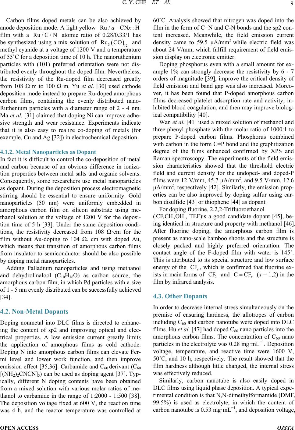 C. Y. CHE ET AL. OPEN ACCESS OJSTA Carbon films doped metals can be also achieved by anode deposition mode. A light yellow film with a atomic ratio of 0.28/0.33/1 has be synthesized using a mix solution of and methyl cyanide at a voltage of 1200 V and a temperature of 55˚C for a deposition time of 10 h. The nanoruthenium particles with (101) preferred orientation were not dis- tributed evenly throughout the doped film. Nevertheless, the resistivity of the Ru-doped film decreased greatly from 108 Ω·m to 100 Ω·m. Yu et al. [30] used cathode deposition mode instead to prepare Ru-doped amorphous carbon films, containing the evenly distributed nano- Ruthenium particles with a diameter range of 2 - 4 nm. Ma et al. [31] claimed that doping Ni can improve adhe- sive strength and wear resistance. Experiments indicate that it is also easy to realize co-doping of metals (for example, Cu and Ag [32]) in electrochemical deposition. 4.1.2. Metal Nanoparticles as Dopant In fact it is difficult to con trol the co-deposition of metal and carbon because of an obvious difference in ioniza- tion properties between metal salts and organic solvents. Consequently, some researchers use metal nanoparticles as dopant. During the deposition process electromagnetic stirring should be essential to ensure uniformity. Gold nanoparticles (50 nm) were uniformly embedded in amo r phous carbon film on silicon substrate using me- thanol solution at the voltage of 1200 V for the deposi- tion time of 5 h [33]. Under the same deposition condi- tions, the resistivity decreased from 108 Ω·cm for the film without Au-doping to 104 Ω. cm with doped Au, which means that transition of amorphous carbon films from insulator to semiconductor should be also possible by doping metal nanoparticles. Adding Palladium nanoparticles and using methanol and dehydrolinalool (C10H16O) as carbon source, the amo rphous carbon film, in which Pd particles with a size of 1 - 5 nm evenly distributed can be successfully achieved [34]. 4.2. Non-Metal Dopants Doping nonmetal into DLC films is directed to enhanc- ing the content of sp2 and improving optical and elec- trical properties. A low emission current greatly limits the application of amorphous films as cold cathode. Doping N into amorphous carbon films can elevate Fer- mi level and lower work function, and then improve emission effect [35,36]. Carbamide and C60 derivant (C60 [(NH2)2CNCN]5) can be used as doping agent [37]. Typ- ically, different N doping contents have been obtained from a mixed solution with various molar ratios of me- thanol to carbamide in the range of 1:2000 - 1:500 [38]. The deposition voltage fixed at 600 V, the reaction time was 4 h, and the reactor temperature was controlled at 60˚C. Analysis showed that nitrogen was doped into the film in the form of C=N and C-N bonds and the sp2 con- tent increased. Meanwhile, the field emission current density came to 59.5 μA /mm2 while electric field was about 24 V/mm, which fulfill requirement of field emis- sion display on electronic emitter. Doping phosphorus even with a small amount for ex- ample 1% can strongly decrease the resistivity by 6 - 7 orders of magnitude [39], improve the critical density of field emission and band gap was also increased. Moreo- ver, it has been found that P-doped amorphous carbon films decreased platelet adsorption rate and activity, in- hibited blood coagulation, and then may improve biolog- ical compatibility [40]. Wan et al. [41] used a mixed solution of methanol and three phenyl phosphate with the molar ratio of 1000:1 to prepare P-doped carbon films. Phosphorus combined with carbon in the form C=P bond and the graphitization degree of the films enhanced confirmed by XPS and Raman spectroscopy. The experiments of the field emis- sion characteristics showed that the threshold electric field and current density for the undoped- and doped-P films were 12 V/mm, 45 .7 μA/mm2, and 9.5 V/mm, 12.6 μA/mm2, respectively [42]. Similarly, the emission pr op- erties can be also improved by doping sulfur using car- bon disul f i de [43] or thiophene [4 4] as dopant. For dopin g fl uorine, 2,2,2-Trifluoroethanol ( , TEF)is a good candidate dopant [45], be- ing identical in structure and property with methanol [46]. After fluorine doping, the amorphous carbon film is present as nano-scale bamboo shoots and the structure is closely packed and highly preferred orientation. The contact angle of the F-doped film with water is 145˚. This is attributed to its special structure and low surface energy of the , which is confirmed that fluorine ex- ists in main forms of and (x = 1,2) in the film by infrared analysis. 4.3. Other Dopants In order to decrease internal stress simultaneously on the premise of ensuring hardness, the allotropes of carbon including C60 and carbon nanotube were doped into DLC films. Hu et al. [47] had doped C60 nano particles into the amorphous carbon films. The concentration of C60 nano particles in the electrolyte was 0.28 mg·mL−1. D eposition voltage, temperature, and reactive time were 1600 V, 50˚C, and 10 h, respectively. The result showed that the film hardness although little changed, the internal stress was effectively reduced. Similarly, carbon nanotube is also easily doped in DLC films using liquid phase deposition. A typical exp e- rimental condition is that N,N-d imethylformamide (DMF, 99.5%) is used as electrolyte, in which the content of carbon nanotube is 0.53 mg· mL −1, and deposition voltage,  C. Y. CHE ET AL. OPEN ACCESS OJSTA temperature, and deposition time are 1400 V, 50 ˚C, and 5 h, respectively [48]. As is known to all, carbon nano- tube possesses excellent mechanical properties including high elastic modulus and toughness because of its special structure [49]. The DLC film after doping carbon nano- tube has changed in property. The internal stress de- creased from 1.2 GPa to 0.83 GPa, hardness increased from 10.28 GPa to 12.47 GPa, and Young modulus de- creased from 253.64 GPa to 206.66 GPa. The spectrum analysis showed that the ratio of sp2 in the film in- creased. Zhang et al. [50] prepared lamellar nano oxidized graphene from liquid phase, and then doped them into DLC film, where methanol used as reactant and the con- tent of the oxidized graphene was 1 mg/ml. Deposition voltage and time were 1200 V and 10 h, respectively. The properties of the DLC films are obviously improved by doping graphite. The hardness and Young modulus are greatly increased from 5.1 GPa and 137.4 GPa to 10.1 GPa and 171.1 GPa, respectively, and the friction coefficient is also decreased significantly. The electrical resistivity decreases from 108 Ω·cm to 102 Ω·cm. The explanation could be the inhibition of plastic deformation and the relaxation of internal stress by the lamellar gra- pheme [51]. An attempt has been made to dope ZrO2 into the car- bon films in our recent research work under low voltage. In the experiments a mixed solution of acetic acid, alco- hol, and deionized water with a volume ratio of 1:4:5 is selected as electrolyte. The presence of acetic acid can provide free hydrogen ions in abundance and alcohol is helpful to get a better suspension with nano ZrO2 par- ticles. Raman spectra of the films deposited at a pulsed voltage of 100 - 200 V and a deposition time of 30min show that there are ZrO2 characteristic strong peaks lo- cated between 200 - 700 cm−1 and a broad peak centered at 1580 cm−1, attributing to amorphous carbon as showed in Figure 3. The film doped ZrO2 nano particles is very smooth and compact, as shown in Figure 4. 5. Existing Problems Liquid electro-deposition technique is a promising me- thod to synthesis amorphous carbon films on the com- plicated workpiece with large area under low temperature. However, there are still some problems to be solved. 1) Mechanical properties and adhesive strength The recent researches focus on chemical components, morphology, and micro-structure. There is few report on the properties of the films deposited from electro-depo- sition because they are poor due to lack of high-energy ion bombardment during the film growth. There is an obviously difference in mechanical properties with the films by vapor phase deposition [53], although some im- provements have been made by doping metal and in- (a) (b) Figure 3. Raman spectra of the films doped with ZrO2 ((a) 0.6 mg/L; (b) 0.2 mg/L) [52]. Figure 4. SEM photograph of the film doped with ZrO2 [52]. troducing additive agent. Table 4 shows the micro-hard- ness of the carbon films deposited using various depos i- tion techniques. 2) The ratio of The properties of DLC films strongly depend on the ratio of [20]. The films deposited by liquid phase method contain too much graphite phase and their  C. Y. CHE ET AL. OPEN ACCESS OJSTA Table 4. Micro-hardness of the carbon films. Films type Preparation method Vickers hardness (Kg/mm2) Reference a-C:H r, f 2000 - 4500 [17] a-C:H r, f 3000 - 5000 [17] a-C:H Ion beam 3000 - 5000 [17] a-C:H Magnet-Sputtering 2500 - 4300 [17] a-C:H DC -3000 [17] Dense Carbon Ion beam ≤6000 [17] nano-particles Electro-deposition ~673 [38] quality is difficult to control. It is necessary to try to find out suitable carbon sources, additive agents, and deposi- tion proce s s. 3) The exploration of deposition mechanism Currently, study on the growth mechanism of carbon films from liquid phase deposition is still in the initial stage. Although some experimental results have been slightly analyzed, it is necessary to establish a perfect theory to guide experimental researches on film growth with high-quality. Prospects With the further research on growth of amorphous car- bon films by electro-deposition, the theory and technol- ogy in this field will be gradually improved. The tech- nique will possess a huge development potential and be widely used to prepare new materials because of unique properties and low cost. Research works in future should be more intensive in the following aspects: 1) selection of carbon sources, additives and dopants; 2) mechanism of formation and stability of amorphous or diamond-like carbon with diamond phase structure; and 3) application of the films. Acknowledgements The project is financially supported by the Cultivation Fund of the Key Scientific and Technical Innovation Project, Ministry of Education (N01707015) and by Ma- jor Project of Chinese National Programs for Fundamen- tal Research and Development (2011CB013402). REFERENCES [1] J. Guo, H. Wang and H. Yan, “Recent Developments in the Preparation of Diamond-Like Carbon Films by the Liquid,” Chemistry Onl ine, Vol. 7, 2007, pp. 521-526. [2] L. I. Maissel and R. Glang, “Handbook of Thin Film Technology,” McGraw-Hill, New York, 1970. [3] Y. Namba, “Attempt to Grow Diamond Phase Carbon Films from an Organic Solution,” Journal of Vacuum Science and Technology A, Vol. 10, 1992, pp. 3368-3370. http://dx.doi.org/10.1116/1.577829 [4] C. B. Cao, H. S. Zhu and H. Wang, “Electrodeposition Diamond-Like Carbon Films from Organic,” Thin Solid Films, Vol. 368, No. 2, 2000, pp. 203-207. http://dx.doi.org/10.1016/S0040-6090(00)00765-3 [5] M. C. Tosin, A. C. Peterlevitz, G. I. Surdutovich and V. Baranauskas, “Deposition of Diamond and Diamond-Like Carbon Nuclei by Electrolysis of Alcohol Solutions,” Ap- plied Surface Science, Vol. 144-145, 1999, pp. 260-264. http://dx.doi.org/10.1016/S0169-4332(98)00808-3 [6] R. S. Li, B. Li u , M. Zhou, Z. X. Zhang, T. Wang, B. A. Lu and E. Q. Xie, “Effect of Deposition Voltage on the Field Emission Properties of Electrodeposited Diamond- Like Carbon Films,” Applied Surface Science, Vol. 255, No. 9, 2009, pp. 4754-4757. http://dx.doi.org/10.1016/j.apsusc.2008.10.053 [7] T. Paulmie r, J. M. Bell and P. M . Frede ricks, “Deposition of Nano-Crystalline Graphite Films by Cathodic Plasma Electrolysis,” T hin Solid Films, Vol. 515, No. 5, 2007, pp. 2926-2934. http://dx.doi.org/10.1016/j.tsf.2006.08.027 [8] Y. Y. He, G. F. Zhang, X. D. Hou and B. S. Cao, “Depo- sition of Diamond-Like Ca rbon Films from 2-Propanolby Liquid Electrochemical Technique,” Materials Review, Vol. 26, No. 6, 2012, pp. 90-92. http://d.g.wanfangdata.com.cn/Periodical_cldb201212026 .aspx [9] J. T. Jiu, K. Cai, Q. Fu, C. B. Cao and H. S. Zhu, “Liquid Deposition of Hydrogenated Carbon Films in N,N-Di- methyl Formamide Solution, ”Materials Letters, Vol. 41, No. 2, 1999, pp. 63-66. http://dx.doi.org/10.1016/S0167-577X(99)00104-4 [10] N. Mayama, H. Yoshida, T. Iwata, K. Sasakawa, A. Su- zuki, Y. Hanaoka, et al., “Characterization of Carbona- ceous Films Deposited on Metal Substrates by Liquid- Phase Electrodeposition in Methanol,” Diamond & Re- lated Materials, Vol. 19, No. 7-9, 2010, pp. 946-949. http://dx.doi.org/10.1016/j.diamond.2010.02.039 [11] K. Sreejith, J. Nuwad and C. G. S. Pillai, “Low Voltage Electrodeposition of Diamond Like Carbon Films,” Ap- plied Surface Science, Vol. 252, No. 2, 2005, pp. 296-302. http://dx.doi.org/10.1016/j.apsusc.2004.11.091 [12] T. Paulmier, L. I. Emadand, J. M. Bellb and P. M. Frede- ricks, “Characterization of Reaction Products and Me- chanisms in Atmospheric Pressure Plasma Deposition of Carbon Films from Ethanol,” Journal of Materials Che- mistry, Vol. 15, 2005, pp. 300-306. http://dx.doi.org/10.1039/b409099c [13] A. I. Kulak, A. I. Kokorin, M. Dieter, V. G. Ralchenko, A. V. Kondratyuk, et al., “Electrodeposition of Nanostruc- tured Diamond-Like Films by Oxidation of Lithium Ace- tylide,” Electrochemistry Communications, Vol. 5, No. 4, 2003, pp. 301-305. http://dx.doi.org/10.1016/S1388-2481(03)00050-X [14] H. Q. Jiang, L. N. Huang, S. J. Wang, et al., “Synthesis of DLC Films by Electrolysis Dimethyl Sulfoxide,” Elec- trochemical and Solid-State Letters, Vol. 7, No. 11, 2004, pp. D19-D21. http://dx.doi.org/10.1149/1.1807531  C. Y. CHE ET AL. OPEN ACCESS OJSTA [15] H. S. Zhu, J. T. Jin, Q. Fu, H. Wang, et al., “Aroused Problems in the Deposition of Diamond-Like Carbon Films by Using the Liquid Phase Electrodeposition Tech- nique,” Journal of Inorganic Materials, Vol. 17, 2002, pp. 571-578. [16] J. A. Dean, “Lange’s Handbook of Chemistry,” 2nd Edi- tion, J. F. Wei, Trans, Science Press, Beijing, 2003. [17] G. F. Zhang, J. Y. Du, Y. Y . He, G. Q. Li and X. D. Hou, “Surface Morphology of Diamond-Like Carbon Films Prepared by Liquid Deposition,” Journal of Chinese Elec- tron Microscopy Society, Vol. 26, No. 1, 2007, pp. 19-23. [18] Y. Li, G. F. Zhang, Y. Y. He and X. D. Hou, “Electrical Double Layer Model and Thermodynamic Coupling for Electrochemically Deposited Hydrogenated Amorphous Carbon Films,” Journal of the Electrochemical Society, Vol. 159, No. 12, 2012, pp. 918-920. http://dx.doi.org/10.1149/2.034212jes [19] S. Gupta, R. K. Roy, B. Deb, S. Kundu and A. K. Pal, “Low Voltage Electrodeposition of Diamond-Like Car- bon Films,” Materials Letters, Vol. 57, No .22-23, 2003, pp. 3479-3485. [20] S. Gupta, M. P. Chowdhury and A. K. Pal, “Synthesis of DLC Films by Electrodeposition Technique Using For- mic Acid as Electroly te,” Diamond & Related Materials, Vol. 13, No. 9, 2004, pp. 1680-1689. http://dx.doi.org/10.1016/j.diamond.2004.02.006 [21] V. P. Novikov and V. P. Dymont, “Synthesis of Di- amond-Like Films by an Electrochemical Method at At- mospheric Pressure and Low Temperature,” Applied Phy- sics Letters, Vol. 70, No. 22-23, 1997, pp. 200-202. http://dx.doi.org/10.1063/1.118355 [22] P. Aublanc, V. P. Novikov, L. V. Kuznetsova and M. Mermoux, “Diamond Synthesis by Electrolysis of Ace- tates,” Diamond and Related Materials, Vol. 10, No. 3-7, 2001, pp. 942-946. [23] E. Matiushenkov, E. Shevchenko, D. Kochubey, D. Svi- ridov, A. Kokorinc and A. Kulak, “Synthesis of Carbon Films with Diamond-Like Structure by Electrochemical Oxidation of Lithium Acetylide,” Chemical Communica- tions, 2001, pp. 317-318. [24] Y. Li, G. F. Zhang, X. D. Hou and D. W. Deng, “Synthe- sis and Tribological Properties of Diamond-Like Carbon Films by Electrochemical Anode Deposition,” Applied Surface Science, Vol. 258, No. 17, 2012, pp. 6527-6530. http://dx.doi.org/10.1016/j.apsusc.2012.03.070 [25] Y. Li, G. F. Zhang, X. D. Hou and D. W. Deng, “Growth Mechanism of Carbon Films from Organic Electrolytes,” Journal of Materials Science, Vol. 48, No. 9, 2013, pp, 3505-3510. [26] J. Robertson, “Diamond-Like Amorphous Carbon,” Ma- terial Science and Engineering Reports, Vol. 258, No. 37, 2002, pp. 129-281. http://dx.doi.org/10.1016/S0927-796X(02)00005-0 [27] S. H. Wan, L. P. Wang and Q. J. Xue, “An Electrochem- ical Strategy to Incorporate Iron into Diamond Like Car- bon Films with Magnetic Properties,” Electrochemistry Communications, Vol. 11, 2009, pp. 99-102. http://dx.doi.org/10.1016/j.elecom.2008.10.037 [28] H. Q. Jiang, L. N. Huang and Z. J. Zhang, “Facile Depo- sition of Copper-Doped Diamond-Like Carbon Nano- composite Films by a Liquid-Phase Electrochemical Route,” Chemistry Communications, Vol. 7, 2004, pp. 2196-2197. http://dx.doi.org/10.1039/b408497g [29] L. N. Huang, H. Q. Jiang and J. S. Zhang, “Synthesis of Copper Nanoparticles Containing Diamond-Like Carbon Films by Electrochem ic al Method,” Electrochemistry Com- munications, Vol. 8, 2006, pp. 262-266. http://dx.doi.org/10.1016/j.elecom.2005.11.011 [30] J. Y. Zhang and Y. L. Yu, “Electrodeposition and Cha- racterization of Pd Nanoparticles Doped Amorphous Hy- drogenated Carbon Films,” Solid State Sciences, Vol. 11, 2009, pp. 1929-1932. http://dx.doi.org/10.1016/j.solidstatesciences.2009.07.012 [31] K. D. Ma. G. B. Yang, L. G. Yu, et al., “Synthesis and Characterization of Nickel-Doped Diamond-Like Carbon Film Electrodeposited at a Low Voltage,” Surface and Coatings Technology, Vol. 204, 2010, pp. 2546-2550. http://dx.doi.org/10.1016/j.surfcoat.2010.01.039 [32] S. Hussain and A. K. Pal, “Synthesis of Composite Films of Mixed Ag-Cu Nanocrystallites Embedded in DLC Ma- trix and Associated Surface Plasmon Properties,” Applied Surface Science, Vol. 253, No. 7, 2007, pp. 3649-3657. http://dx.doi.org/10.1016/j.apsusc.2006.07.074 [33] G. Chen, J. Y. Zhang and S. R. Yang, “A Novel Method for the Synthesis of Au Nanoparticles Incorporated Amor - phous Hydrogenated Carbon Films,” Electrochemistry Communications, Vol. 9, 2007, pp. 1053-1056. http://dx.doi.org/10.1016/j.elecom.2006.12.019 [34] Y. L. Yu, S. Liu and J. Y. Zhang, “Cathode Electrodepo- sition and Characterization of Ru Nanoparticles Doped a-CNx:H Composite Films,” Diamond and Related Mate- rials, Vol. 19, 2010, pp. 661-664. http://dx.doi.org/10.1016/j.diamond.2010.02.028 [35] D. S. Mao, J. Zhao and W. Li, “Electron Field Emission from Nitrogen-Containing Diamond-Like Carbon Films Deposited by Filtered Arc Deposition,” Materials Letters, Vol. 41, No. 3, 1999, pp. 117-121. http://dx.doi.org/10.1016/S0167-577X(99)00115-9 [36] A. A. Eytikh, H. Hartnagel and V. G. Litovchenko, “En- hancement of Electron Field Emission Stability by Nitro- gen-Doped Diamond-Like Carbon Film Coating,” Semi- conductor Science and Technology, Vol. 19, 2004, pp. 923-929. http://dx.doi.org/10.1088/0268-1242/19/7/025 [37] Y. L. Yu and J. Y. Zhang, “Ultrafast Electrodeposition of Amorphous Carbon Nitride Films from Fullerene Deriva- tive,” Electrochemistry Communications, Vol. 12, 2010, pp. 390-393. doi.org/10.1016/j.elecom.2010.01.001 [38] R. S. Li, E. Q. Xie, M. Zhou, Z. X. Zhang, T. Wang and B. A. Lu, “Field Emission Properties of Nitrogen Incor- porated DLC Films Prepared by El ectrodeposition,” Ap- plied Surface Science, Vol. 255, 2008, pp. 2787-2790. http://dx.doi.org/10.1016/j.apsusc.2008.08.010 [39] J. Yuan, V. S. Veerasamy, G. A. J. Amaratunga, W. I. Milne, K. W. R. Gilkes, M. Weiler, et al., “Nitrogen Doping of Highly Tetrahedral Amorphous Carbon,” Phy- sical Review B, Vol. 48, No. 24, 1993, pp. 17954-17959. http://dx.doi.org/10.1103/PhysRevB.48.17954  C. Y. CHE ET AL. OPEN ACCESS OJSTA [40] S. C. H. Kwoka, J. Wanga and P. K. Chu, “Surface Energy, Wettability, and Blood Compatibility Phosphorus Doped Diamond-Like Carbon Films,” Diamond & Related Ma- terials, Vol. 14, No. 1, 2005, pp. 78-85. http://dx.doi.org/10.1016/j.diamond.2004.07.019 [41] S. H. Wan, H. Y. Hu, G. Chen and J. Y. Zhang, “Synthe- sis and Characterization of High Voltage Electrodeposited Phosphorus Doped DLC Films,” Electrochemistry Com- munications,” Vol. 10, 2008, pp. 461-465. http://dx.doi.org/10.1016/j.elecom.2008.01.003 [42] S. H. Wan, L. P. Wang, J. Y. Zhang and Q. J. Xue, “Field Emission Properties of DLC and Phosphorus-Doped DLC Films Prepared by Electrochemical Deposition Process,” Applied Surface Science, Vol. 255, 2009, pp. 3817-3821. http://dx.doi.org/10.1016/j.apsusc.2008.10.061 [43] S. Kundoo, P. Saha and K. K. Chattopadhyay, “Electron Field Emission from Nitrogen and Sulfur-Doped Di- amond-Like Carbon Films Deposited by Simple Electro- chemical Route,” Materials Letters, Vol. 58, No. 30, pp. 3920-3924. http://dx.doi.o rg/10. 1016/j. matle t.2004. 08.018 [44] S. H. Wan, L. P. Wang and Q. J. Xue, “Electrochemical Deposition of Sulfur Doped DLC Nanocomposite Film at Atmospheric Pressure,” Electrochemistry Communica- tions, Vol. 12, No. 1, 2010, pp. 61-65. http://dx.doi.org/10.1016/j.elecom.2009.10.036 [45] J. Y. Zhang, G. Chen and S. G. Yang, “Fabrication of Hydrophobic Fluorinated Amorphous Carbon Thin Films by a n Electrochemical Route,” Electrochemistry Commu- nications, Vol. 10, 2008, pp. 7-11. http://dx.doi.org/10.1016/j.elecom.2007.10.006 [46] H. Y. Hu, G. Chen and J. Y. Zhang, “Synthesis of C60 Nanoparticle Doped Hard Carbon Film by Electrodeposi- tion,” Carbon, Vol. 46, 2008, pp. 1095-1097. http://dx.doi.org/10.1016/j.carbon.2008.03.012 [47] H. Y. Hu, G. Chen and J. Y. Zhang, “Facile Synthesis of CNTs-Doped Diamond-Like Carbon Film by Electrode- position,” Surface and Coating Technology, Vol. 202, 2008, pp. 5943-5946. http://dx.doi.org/10.1016/j.surfcoat.2008.06.162 [48] Z. J. Zhang, S. S. Fan, J. L. Huang, et al., “Pulsed Laser Deposition and Physical Properties of Carbon Nitride Thin Films,” Journal of Electronic Materials, Vol. 25, No. 1, 1996, pp. 57-61. http://dx.doi.org/10.1007/BF02666174 [49] J. Y. Zhang, Y. L. Yu and D. M. Hua ng, “Good Electrical and Mechanical Properties Induced by the Multilayer Graphene Oxide Sheets Incorporated to Amorphous Car- bon Films,” Solid State Sciences, Vol. 12, 2010, pp. 1183- 1187. http://dx.doi.org/10.1016/j.solidstatesciences.2010.03.017 [50] C. G. Lee, X. D. Wei, J. W. Kysar and H. James, “Mea- surement of the Elastic Properties and Intrinsic Strength of Monolayer Graphene,” Science, Vol. 321, 2008, pp. 385-388. http://dx.doi.org/10.1126/science.1157996 [51] N. K. Xu, A. C. Yin, G. F. Zhang and X. L. Zheng, “Ha r d- ness Mesurements of DLC Films,” Mechanical Science and Technology, Vol. 16, 1997, pp. 1063-1070. [52] Y. Li, “Amorphous Carbon Films Deposited by Cathodic and Anodic Deposition Modes,” Dalian University of Technology, Dalian, 2013, pp. 24-27. [53] G. H. Chen and Y. H. Lu, “Hardness of DLC Films De- posited on Stainless Steel,” Journal of Inorganic Mate- rials, Vol. 11, No. 4, 1996, pp. 635-649.
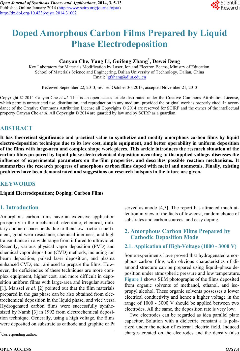
|