Open Journal of Antennas and Propagation, 2013, 1, 49-56
Published Online December 2013 (http://www.scirp.org/journal/ojapr)
http://dx.doi.org/10.4236/ojapr.2013.13009
Open Access OJAPr
49
Dielectric Loading on Multi-Band Behaviors of Pentagonal
Fractal Patch Antennas
Ravindra Kumar Yadav1, Jugul Kishor2, R. L. Yadava3
1Department of Electronics and Communication Engineering, JRE School of Engineering, Greater Noida, India; 2Department of
Electronics and Communication Engineering, ITS Engineering College, Greater Noida, India; 3Department of Electronics and Com-
munication Engineering, Galgotia’s College of Engineering and Technology, Greater Noida, India.
Email: ravipusad@gmail.com, jugulkishor@gmail.com, rly1972@gmail.com
Received October 20th, 2013; revised November 18th, 2013; accepted December 13th, 2013
Copyright © 2013 Ravindra Kumar Yadav et al. This is an open access article distributed under the Creative Commons Attribution
License, which permits unrestricted use, distribution, and reproduction in any medium, provided the original work is properly cited.
ABSTRACT
This paper describes the multiband behaviour as well as the response for dielectric loading of a pentagonal fractal patch
antenna designed at frequency f = 2.45 GHz. The proposed antenna shape has been obtained by introducing slots in a
pentagonal patch antenna up to second iteration. Detailed design steps and results of the designs are studied and inves-
tigated in this paper. Simulated and measured results reveal that the antenna will be operated at three different fre-
quency bands—2.17 GHz, 3.56 GHz, and 7.93 GHz with acceptable performances (i.e. VSWR < 2). The measured re-
sults for the antennas are in good agreement with simulated results. The proposed antenna maintains good radiation
pattern with gain. However dielectric loading increases its radiation efficiency at the cost of significant decrease in gain
and directivity.
Keywords: Fractal Patch Antenna; Multiband; Pentagonal Patch and Dielectric Loading
1. Introduction
The modern telecommunication system requires antennas
that have multiband and wider bandwidth characteristics
as well as smaller dimensions than conventionally possi-
ble ones. In the recent years, the self-similar and space
filling nature of fractal geometry has motivated antenna
designers to adopt this geometry as a viable alternative to
meet the target of multiband operation. The self-similar
and scaling properties of fractal geometries characterize
these structures [1]. In 1998, Z. Baharav presented his
work on fractal arrays based on iterated function systems.
Self-similar feature in the radiation patterns allows a
multi-band frequency usage of the fractal array [2]. In
1999, M. Navarro et al. worked on the topic “Self-similar
surface current distribution on the fractal Sierpinski an-
tenna verified with Infra-red Thermograms” [1]. In this
research, he presented the experimental verification of
the fractal Sierpinski Antenna surface’s current distribu-
tion. In 2001, P. Felber reported that due to the space
filling properties of fractals, antennas designed from cer-
tain fractal shapes can have far better electrical to physi-
cal size ratios than conventional antennas [3]. In 2004, K.
Sathya performed research on size reduction of low fre-
quency microstrip patch antenna with Koch shaped frac-
tal slot and a size reduction about 84% [4]. In 2005, P.
Hazadra and M. Mazánek performed the research on
model analysis of fractal microstrip patch antennas and
the obtained results found in good agreement with the
simulated one [5]. Later in 2006, V. Gupta and N. Gupta
conducted research on “Two compact microstrip patch
antenna for 2.4 GHz band”, in which two low profile
patch antennas for wireless LAN 802.11b communica-
tion standard were designed and investigated, however,
performed analysis of a fractal microstrip patch antenna
was done in 2007 [6,7]. In 2008, F. H. Kashani et al.
studied a novel broadband fractal Sierpinski shaped, mi-
crostrip antenna, and found that this antenna with a mul-
tilayer structure behaves in 7 - 10.6 GHz portion which
overlaps the UWB range [8].
However in 2009, A. Azari designed an ultra wide
band hexagonal fractal microstrip antenna and found that
the antenna has multiband behavior, and significant gain
improvement was also achieved [9]. In 2010, F. J. Jibrael
et al. presented a research paper entitled “A new multi-
band patch microstrip plusses fractal antenna”, and
proposed that the antenna has an excellent size reduction
Dielectric Loading on Multi-Band Behaviors of Pentagonal Fractal Patch Antennas
50
possibility with good radiation performance for wireless
applications [10]. However, L. Economou et al. [11]
analyzed circular patches printed on RT Duroid, with
glass laminated superstrates and found that the glass im-
proved the bandwidth of the antenna. Latter, D. D.
Krishna et al. [12] proposed a dielectric loaded slotted
circular dual frequency microstrip antenna and observed
that the superstrate, not only acts as a random, but also
improves the operating bandwidth of the antenna. Sev-
eral research works have been reported on fractal patch
antennas and the microstrip patch antenna, but not much
attention has been paid on dielectric loaded fractal patch
antennas, though such loading severely affects the per-
formance characteristics of the patch antennas.
Therefore, in this paper authors have designed the
pentagonal fractal patch antennas and made an attempt to
investigate the effects of dielectric loading on the behav-
ior of the antenna. The novelty of this work presented
here is that the environmental effect on fractal patch an-
tenna has been analyzed. We considered here rain at-
tenuation as an environmental parameter and analysed
performance degradation of fractal patch antenna. Figure
1 shows the geometrical configuration of proposed pen-
tagonal fractal patch antenna up to second iterations.
2. Design of Antenna Geometry
A pentagonal microstrip patch antenna gives better per-
formance than the rectangular patch antenna; in particu-
lar, it supports both linear and circular polarizations [13]
(Figure 2). The pentagonal patch antenna provides cir-
cular polarization with only one feed where as rectangu-
lar patch antenna requires multiple feeds to get circular
polarizations. Hence the proposed antenna geometry is
chosen to be a pentagonal patch antenna and fed with a
50 coaxial cable for better impedance matching. This
has later been converted into fractal patch antenna ac-
companying pentagonal slots using a finite number of
iterations. The pentagonal antenna size calculations were
made considering the invariance of the electrostatic en-
ergy below the pentagonal and circular patches, keeping
their areas remain constant [14]. The relationship be-
tween the circles (r1) to the side arm of the regular pen-
tagon (r2) is given in Equation (1).
2
21
22.37
r
r
(1)
Zero Iteration First Iteration Second Iteration
Figure 1. Geometry of proposed fractal antennas.
Side arm of the pentagon (r2) = 1.175 r1.
In the derivation of the expression (1), the pentagonal
patch is assumed to be a resonant cavity with perfectly
conducting side walls.
Because a circular disc is the limiting case of the po-
lygon with large number of sides, in this case number of
sides are 5. The resonant frequency of the dominant as
well as for the higher order modes can be calculated from
the formula given below:
'
1
2
np
np
r
X
c
fr
(2)
where '
np
X
are the zeros of the derivative of the Bessel
function
n
J
x of the order n, as is true for TE mode
circular waveguides, however for the lowest order mod-
es;
'1.84118
np
X
The lengths of each side of the pentagonal antenna are
calculated by using Equations (1) & (2). For coaxial
feeds, the location of the feed point is usually selected to
provide a good impedance match.
3. Fractal Antenna Generation and
Antenna Geometry
In this we illustrate the design procedure of the fractal
patch antenna for multiband application. In this design
procedure a pentagonal antenna is converted into the
fractal patch antenna by the introduction of the pentago-
nal sot. In 1st iteration a pentagonal slot is introduced in
the centre of the patch. For the modification of the basic
geometry, the size of the slot is 1/5 to the size of the ba-
sic geometry. Similarly, in the second stage, a set of two
pentagon slots is inserted; the size of the each slot is 1/6
to the size of the basic geometry. Due to these slots, the
antenna posses the characteristics of multi-band fre-
quency operation.
Using design parameters (Ta bl e 1) a pentagonal an-
tenna is designed and simulated using HFSS, which has
been taken as 0th iteration or the base geometry of pro-
r
1
r
2
Figure 2. Geometry of a regular pentagonal shape.
Open Access OJAPr
Dielectric Loading on Multi-Band Behaviors of Pentagonal Fractal Patch Antennas 51
Table 1. Design specifications for proposed antennas.
Geometry Pentagonal
Side arm length 22.58 mm
Substrate (FR-4) εr = 4.4, h = 0.8 mm,
tanδ = 0.002
Centre frequency 2.45 GHz
Feed location (from center) 8.21 mm
Inner radius: 0.5 mm
Coaxial cable dimension
Outer radius: 0.9 mm
Dielectric cover (distilled water) εr = 81, h = 0.1 mm to 0.3 mm
posed fractal patch antenna as shown in the Figure 3.
Each side of the patch is of 22.58 mm, and the antenna
has been designed on a FR-4 substrate with relative per-
mittivity (εr) 4.4, loss tangent 0.002 and substrate thick-
ness of 0.8 mm using the Equations (1) & (2).
To obtain dual band behavior the 1st iteration of this
fractal patch has been obtained by etching a pentagonal
slot having side arm 4.7 mm without changing the origi-
nal structure of the patch as shown in the Figure 4.
However for multiband behavior 2nd iteration of the
fractal patch has been obtained by etching two pentago-
nal slot having side arm 3.4 mm without changing the
original structure of the patch as shown in the Figure 5.
4. Results and Discussions
4.1. Pentagonal Fractal Patch Antennas
The geometry shown in Figures 3-5 is simulated using
the HFSS software and the return loss characteristics
obtained has been shown in the Figure 6. From which
return loss of 18.37 dB at a resonant frequency of 2.44
GHz has been obtained for 0th iteration. From the return
loss characteristics one may find the presence of dual
bands having return loss of 10.88 dB at 2.30 GHz,
18.10 dB at 3.88 GHz for 1st iteration. However for the
2nd iterated simulation results we find the antenna is re-
sonating at three different resonant frequencies. We may
view the return loss of 16.69 dB at 2.17 GHz, 16.17
dB at 3.56 GHz, 19.64 dB at 7.9315 GHz, which satisfy
the requirement of multi-banding behavior of antenna.
Figure 7 illustrates comparison of measured and si-
mulated results, which are in good agreement and verify
the multi band behavior of the 2nd iterated fractal patch
antenna with return loss of 18.2 dB at 2.17 GHz, 24.81
dB at 3.61 GHz and 19.64 dB at 7.93 GHz. Simulated
and measured return loss are also tabulated in Ta b les 2
and 3 respectively.
Figure 8 shows the simulated input impedance of the
fractal patch antenna for 0th, 1st and 2nd iteration. Simu-
lated results of the input impedances are also tabulated in
Figure 3. Geometry of 0th iteration pentagonal patch an-
tenna.
Figure 4. Geometry of 1st iteration pentagonal patch an-
tenna.
Figure 5. Geometry of 2nd iteration pentagonal patch an-
tenna.
Table 2.
Figure 9 shows the simulated VSWR of the fractal
patch antenna for 0th, 1st and 2nd iteration and observed
that VSWR is less than 2 at the resonant frequencies.
Simulated VSWR results are also tabulated in the Table
2.
The radiation pattern of the 0th iteration of fractal patch
antenna has been shown in the Figure 10. From this rad-
Open Access OJAPr
Dielectric Loading on Multi-Band Behaviors of Pentagonal Fractal Patch Antennas
52
25
20
15
10
5
0
1.1 2.1 3.1 4.1 5.1 6.1 7.1 8.1 9.1
S11(dB)
Frequency (GHz)
0th iteration_Simulated
1st iteration_Simulated
2nd iteration_Simulated
S
11
Figure 6. Comparisons of simulated return loss characteris-
tics of the fractal patch antennas.
25
20
15
10
5
0
13579
S11(dB)
Frequency (GHz)
dB(S11)_Simulated
dB(S11)_Measured
S
11
S
11
S
11
Figure 7. Comparisons of measured and simulated return
loss characteristics of the 2nd iterated fractal patch antenna.
0
10
20
30
40
50
60
70
80
90
1.2 3.2 5.2 7.2 9.2
Z11()
Frequency (GHz)
0th Iteration
1st Iteration
2nd Iteration
Z
11
Figure 8. Comparisons of Input Impedance of the fractal
patch antenna.
0
1
2
3
4
5
6
1.5 2.5 3.5 4.5 5.5 6.5 7.5 8.5 9.5
SWR
Frequency (GHz)
0th Iteration
1st Iteration
2nd Iteration
Figure 9. Comparison of VSWR of the fractal patch an-
tenna.
iation pattern we can find that the maximum achieved
gain is 1.3 dBi. The radiation pattern of 1st iteration of
fractal patch antenna at both resonant frequencies has
been shown in the Figure 11, which gives the maximum
gain of 2.15 dBi at 2.3 GHz and 4.0 dBi at 3.88 GHz.
Figure 10. Radiation pattern at E-plane and H-plane for 0th
iteration at 2.44 GHz.
Figure 11. Radiation pattern at E-plane and H-plane for 1st
iteration at 2.30 GHz and 3.88 GHz.
Table 2. Simulated return loss, impedance and VSWR of
the proposed fractal patch antenna.
Types Frequency
(GHz) S11 (dB) Impedance
() VSWR
0th Iteration2.44 18.37 44.61 1.27
2.30 10.88 85.73 1.79
1st Iteration
3.88 18.10 51.52 1.28
2.17 16.69 62.46 1.33
3.56 16.17 37.20 1.36 2nd Iteration
7.93 19.64 42.00 1.23
The radiation pattern and gain of the 2nd iteration, at all
three resonant frequencies have been illustrated in the
Figures 12 and 13. One may be able to observe that
maximum achieved gain at 2.17 GHz is 2 dBi, at 3.56
GHz is 5.00 dBi, and at 7.93 GHz is 1.0 dBi. Table 4
Open Access OJAPr
Dielectric Loading on Multi-Band Behaviors of Pentagonal Fractal Patch Antennas 53
Table 3. Measured return loss for 2nd iteration fractal an-
tenna.
Type Simulated Frequency (GHz) S
11 (dB)
2.17 18.92
3.61 24.81
2nd Iteration
7.93 19.64
Figure 12. Radiation pattern at E-plane for 2nd iteration at
2.17 GHz, 3.56 GHz and 7.93 GHz.
Figure 13. Radiation pattern at H-plane for 2nd iteration at
2.17 GHz, 3.56 GHz and 7.93 GHz.
presents various parameters like directivity, gain and
radiated power at all resonant frequencies. While ex-
perimental set up used for measurement and obtained
results are shown in Figures 14 and 15 respectively.
4.2. Pentagonal Fractal Patch Antennas with
Dielectric Loading
The dielectric loading changes the resonance frequency,
Table 4. Simulated directivity, gain, radiated power and
radiation efficiency of the fractal patch antenna.
Types Frequency
(GHz) Directivity Gain
(dBi)
Radiated
power (mW)
0th
Iteration 2.44 0.81 1.3 10.00
2.30 0.75 2.15 5.00
1st
Iteration 3.88 0.49 4.00 7.8
2.17 0.74 2.00 6.9
3.56 0.43 5.00 10.8
2nd
Iteration
7.93 1.58 1.00 4.2
Figure 14. Antenna measurement setup.
Figure 15. Measured results of the 2nd iterated fractal patch
antenna.
gain, radiation efficiency and bandwidth of the conven-
tional patch antennas, and amount of effects vary with
thickness of dielectric, types of dielectrics, impedance
matching and polarization. The study shows that resonant
frequency decreases with increasing the thickness of di-
electric. The maximum value of the radiation efficiency
Open Access OJAPr
Dielectric Loading on Multi-Band Behaviors of Pentagonal Fractal Patch Antennas
54
is obtained in the case of an antenna with different sub-
strate and dielectric materials than that of an antenna
with substrate and dielectric of same dielectric. As re-
ported in reference [15], due to dielectric loading, ca-
pacitance of the antenna system increases, which de-
creases the overall performances of the antenna such as
resonant frequency, impedance bandwidth and radiating
efficiency.
Hence, in order to observe the effects of dielectric
loadings on the antenna characteristics, the proposed
antenna has been analyzed and tested using water as a
dielectric cover. The obtained characteristics are shown
in Figures 16-19; and the simulated and measured results
are also tabulated in Ta bl es 5 and 6 respectively. Meas-
ured results for the fractal patch antennas without and
with a dielectric cover of thickness 0.3 mm are shown in
Figures 17 and 20. Measured results shows shift in
resonance frequency, which are due to non uniform dis-
tribution of water layer on the patch antenna surface and
inability to measure exact water level thickness on the
patch surface.
35
30
25
20
15
10
5
0
12345678910
S11(dB)
Frequency (GHz)
S11 at t=0 mm
S11 at t=0.1 mm
S11 at t=0.2 mm
S11 at t=0.3 mm
S11
S
11
S
11
S
11
S
11
Figure 16. Comparisons of simulated return loss character-
istics of the fractal patch antenna with dielectric cover.
35
30
25
20
15
10
5
0
0246810
S11(dB)
Frequency(GHz)
12
S11 at t=0.3 mm
S11 _Measured at t=0.3 mm
S
11
S
11
S
11
Figure 17. Comparisons of measured and simulated return
loss characteristics of the 2nd iterated fractal patch antenna
for dielectric cover of 0.3 mm.
0
1
2
3
4
5
6
1.5 2.5 3.5 4.5 5.5 6.5 7.5 8.5 9.5
VSWR
Frequency (GHz)
VSWR at t='0mm'
VSWR at t='0.1 mm'
VSWR at t='0.2 mm'
VSWR at t='0.3mm'
Figure 18. Frequency response of VSWR with dielectric
cover.
0
15
30
45
60
75
13579
Z11,
Fre
q
uenc
y
(
GHz
)
mag(Z11)at t='0mm'
mag(Z11)at t='0.1mm'
mag(Z11)at t='0.2mm'
mag(Z11)at t='0.3mm'
Z
11
Z
11
Z
11
Z
11
Z
11
Figure 19. Input impedance with dielectric covers.
Figure 20. Measured results of the fractal patch antennas
with dielectric cover of 0.3 mm.
5. Conclusion
In this work, we analyse the effect of water accumulation
on the surface of the fractal patch antenna. Accumulation
of rain water on the top of the antenna surface for highly
resonant (high Q-value) microstrip antennas makes them
prone to frequency shift as well as impedance mismatch.
Open Access OJAPr
Dielectric Loading on Multi-Band Behaviors of Pentagonal Fractal Patch Antennas 55
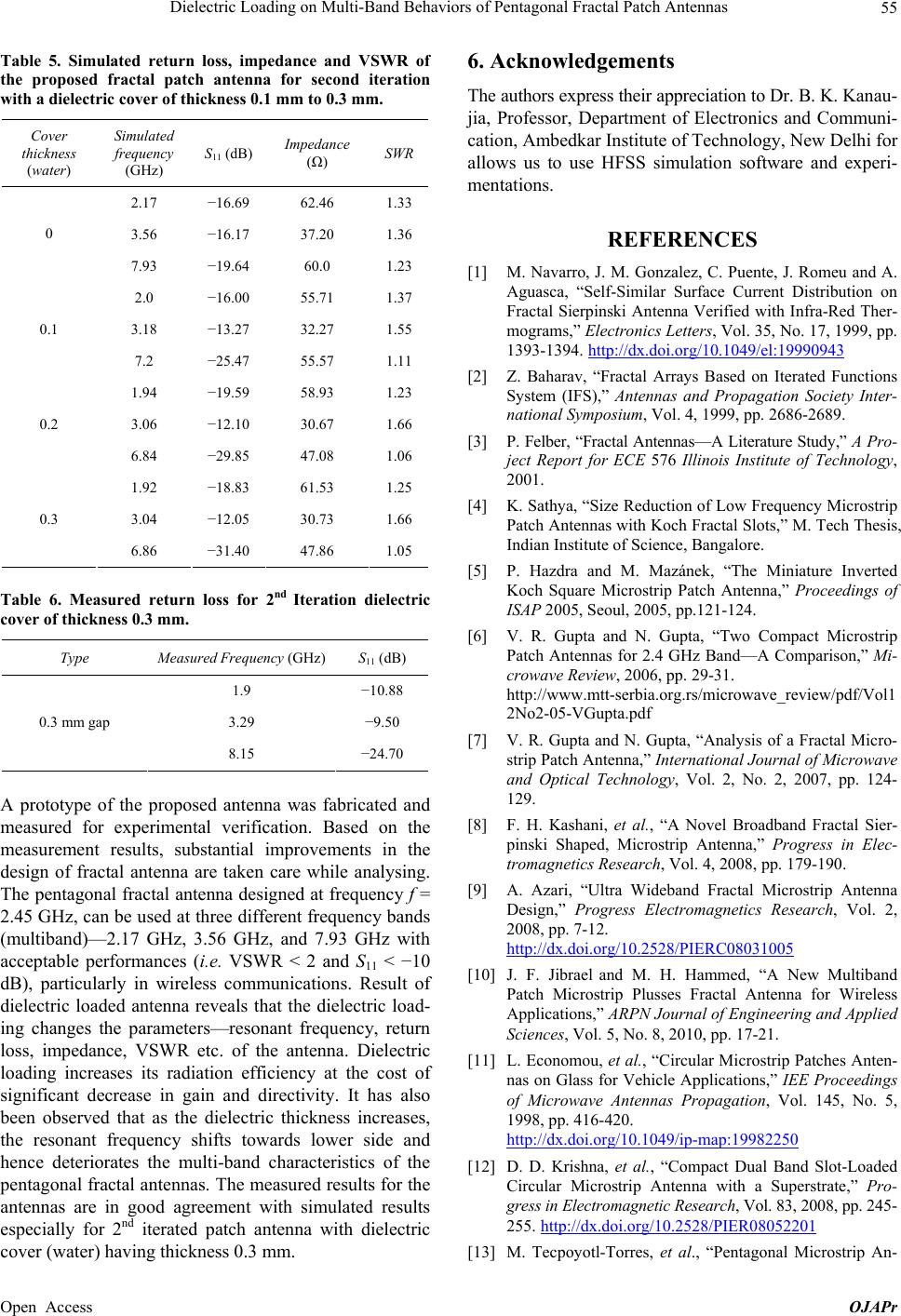
Table 5. Simulated return loss, impedance and VSWR of
the proposed fractal patch antenna for second iteration
with a dielectric cover of thickness 0.1 mm to 0.3 mm.
Cover
thickness
(water)
Simulated
frequency
(GHz)
S11 (dB) Impedance
() SWR
2.17 16.69 62.46 1.33
3.56 16.17 37.20 1.36
0
7.93 19.64 60.0 1.23
2.0 16.00 55.71 1.37
3.18 13.27 32.27 1.55
0.1
7.2 25.47 55.57 1.11
1.94 19.59 58.93 1.23
3.06 12.10 30.67 1.66
0.2
6.84 29.85 47.08 1.06
1.92 18.83 61.53 1.25
3.04 12.05 30.73 1.66
0.3
6.86 31.40 47.86 1.05
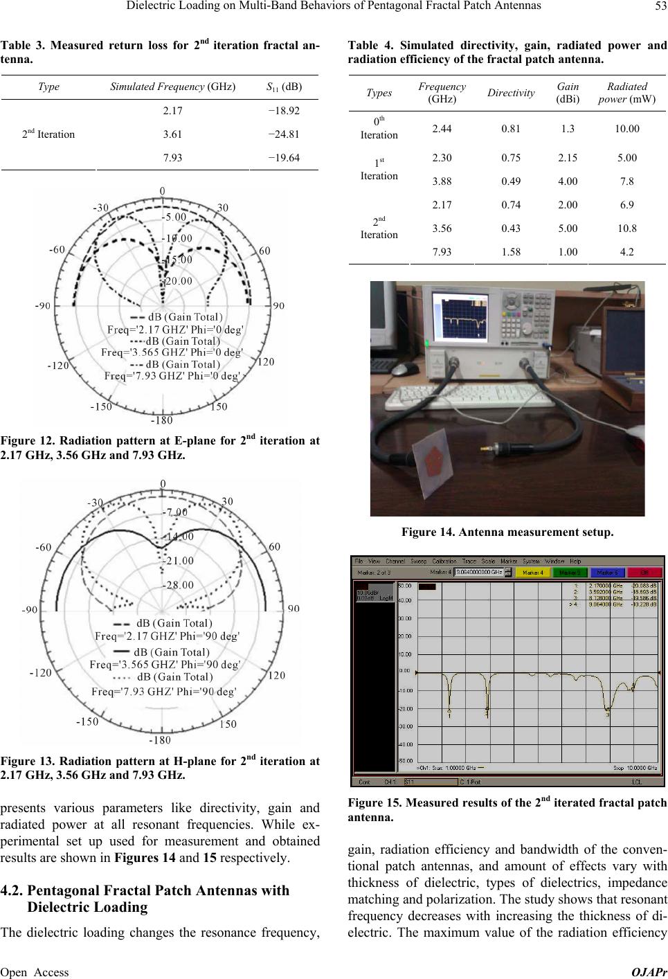
Table 6. Measured return loss for 2nd Iteration dielectric
cover of thickness 0.3 mm.
Type Measured Frequency (GHz) S
11 (dB)
1.9 10.88
3.29 9.50
0.3 mm gap
8.15 24.70
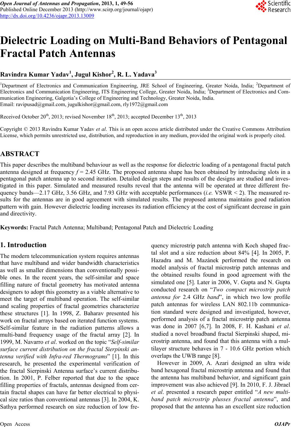
A prototype of the proposed antenna was fabricated and
measured for experimental verification. Based on the
measurement results, substantial improvements in the
design of fractal antenna are taken care while analysing.
The pentagonal fractal antenna designed at frequency f =
2.45 GHz, can be used at three different frequency bands
(multiband)—2.17 GHz, 3.56 GHz, and 7.93 GHz with
acceptable performances (i.e. VSWR < 2 and S11 < 10
dB), particularly in wireless communications. Result of
dielectric loaded antenna reveals that the dielectric load-
ing changes the parameters—resonant frequency, return
loss, impedance, VSWR etc. of the antenna. Dielectric
loading increases its radiation efficiency at the cost of
significant decrease in gain and directivity. It has also
been observed that as the dielectric thickness increases,
the resonant frequency shifts towards lower side and
hence deteriorates the multi-band characteristics of the
pentagonal fractal antennas. The measured results for the
antennas are in good agreement with simulated results
especially for 2nd iterated patch antenna with dielectric
cover (water) having thickness 0.3 mm.
6. Acknowledgements
The authors express their appreciation to Dr. B. K. Kanau-
jia, Professor, Department of Electronics and Communi-
cation, Ambedkar Institute of Technology, New Delhi for
allows us to use HFSS simulation software and experi-
mentations.
REFERENCES
[1] M. Navarro, J. M. Gonzalez, C. Puente, J. Romeu and A.
Aguasca, “Self-Similar Surface Current Distribution on
Fractal Sierpinski Antenna Verified with Infra-Red Ther-
mograms,” Electronics Letters, Vol. 35, No. 17, 1999, pp.
1393-1394. http://dx.doi.org/10.1049/el:19990943
[2] Z. Baharav, “Fractal Arrays Based on Iterated Functions
System (IFS),” Antennas and Propagation Society Inter-
national Symposium, Vol. 4, 1999, pp. 2686-2689.
[3] P. Felber, “Fractal Antennas—A Literature Study,” A Pro-
ject Report for ECE 576 Illinois Institute of Technology,
2001.
[4] K. Sathya, “Size Reduction of Low Frequency Microstrip
Patch Antennas with Koch Fractal Slots,” M. Tech Thesis,
Indian Institute of Science, Bangalore.
[5] P. Hazdra and M. Mazánek, “The Miniature Inverted
Koch Square Microstrip Patch Antenna,” Proceedings of
ISAP 2005, Seoul, 2005, pp.121-124.
[6] V. R. Gupta and N. Gupta, “Two Compact Microstrip
Patch Antennas for 2.4 GHz Band—A Comparison,” Mi-
crowave Review, 2006, pp. 29-31.
http://www.mtt-serbia.org.rs/microwave_review/pdf/Vol1
2No2-05-VGupta.pdf
[7] V. R. Gupta and N. Gupta, “Analysis of a Fractal Micro-
strip Patch Antenna,” International Journal of Microwave
and Optical Technology, Vol. 2, No. 2, 2007, pp. 124-
129.
[8] F. H. Kashani, et al., “A Novel Broadband Fractal Sier-
pinski Shaped, Microstrip Antenna,” Progress in Elec-
tromagnetics Research, Vol. 4, 2008, pp. 179-190.
[9] A. Azari, “Ultra Wideband Fractal Microstrip Antenna
Design,” Progress Electromagnetics Research, Vol. 2,
2008, pp. 7-12.
http://dx.doi.org/10.2528/PIERC08031005
[10] J. F. Jibrael and M. H. Hammed, “A New Multiband
Patch Microstrip Plusses Fractal Antenna for Wireless
Applications,” ARPN Journal of Engineering and Applied
Sciences, Vol. 5, No. 8, 2010, pp. 17-21.
[11] L. Economou, et al., “Circular Microstrip Patches Anten-
nas on Glass for Vehicle Applications,” IEE Proceedings
of Microwave Antennas Propagation, Vol. 145, No. 5,
1998, pp. 416-420.
http://dx.doi.org/10.1049/ip-map:19982250
[12] D. D. Krishna, et al., “Compact Dual Band Slot-Loaded
Circular Microstrip Antenna with a Superstrate,” Pro-
gress in Electromagnetic Research, Vol. 83, 2008, pp. 245-
255. http://dx.doi.org/10.2528/PIER08052201
[13] M. Tecpoyotl-Torres, et al., “Pentagonal Microstrip An-
Open Access OJAPr
Dielectric Loading on Multi-Band Behaviors of Pentagonal Fractal Patch Antennas
Open Access OJAPr
56
tenna Equivalent to a Circular Microstrip Antenna for
GPS Operation Frequency,” Programación Matemática y
Software, Vol. 1, No. 2, 2009, pp. 200-208.
[14] G. Kumar and K. P. Ray, “Broadband Microstrip Anten-
nas,” Artech House Publishers, London, 2003.
[15] I. Bahl, P. Bhartia and S. Stuchly, “Design of Microstrip
Antennas Covered with a Dielectric Layer,” IEEE Trans-
actions on Antennas and Propagation, Vol. 30, No. 2,
1982, pp. 314-318.
http://dx.doi.org/10.1109/TAP.1982.1142766