FDTD Analysis of Millimeter Wave Binary Photon Sieve Fresnel Zone Plate 47
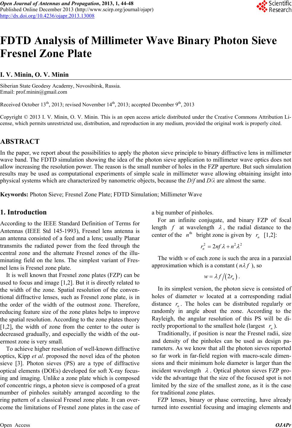
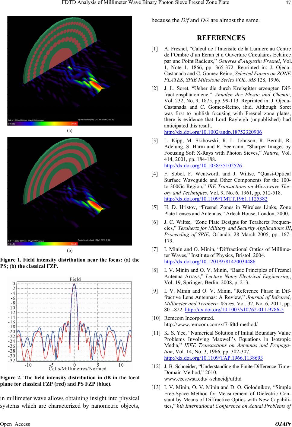
(a)
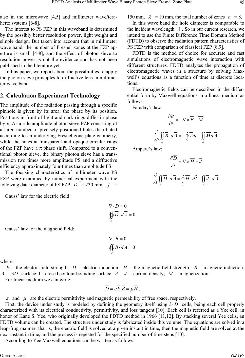
(b)
Figure 1. Field intensity distribution near the focus: (a) the
PS; (b) the classical FZP.
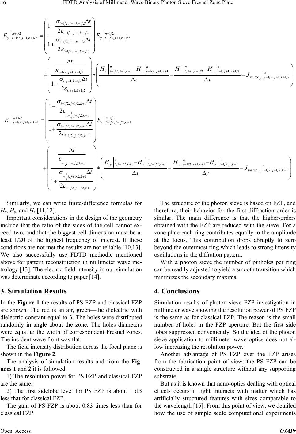
Figure 2. The field intensity distribution in dB in the focal
plane for classical FZP (red) and PS FZP (blue).
in millimeter wave allows obtaining insight into physical
systems which are characterized by nanometric objects,
because the D/f and D/λ are almost the same.
REFERENCES
[1] A. Fresnel, “Calcul de l’Intensite de la Lumiere au Centre
de l’Ombre d’un Ecran et d Ouverture Circulaires Eclairee
par une Point Radieux,” Oeuvres d’Augustin Fresnel, Vol.
1, Note 1, 1866, pp. 365-372. Reprinted in: J. Ojeda-
Castanada and C. Gomez-Reino, Selected Papers on ZONE
PLATES, SPIE Milestone Series VOL. MS 128, 1996.
[2] J. L. Soret, “Ueber die durch Kreisgitter erzeugten Dif-
fractionsphänomene,” Annalen der Physic und Chemie,
Vol. 232, No. 9, 1875, pp. 99-113. Reprinted in: J. Ojeda-
Castanada and C. Gomez-Reino, ibid. Although Soret
was first to publish focusing with Fresnel zone plates,
there is evidence that Lord Rayleigh (unpublished) had
anticipated this result.
http://dx.doi.org/10.1002/andp.18752320906
[3] L. Kipp, M. Skibowski, R. L. Johnson, R. Berndt, R.
Adelung, S. Harm and R. Seemann, “Sharper Images by
Focusing Soft X-Rays with Photon Sieves,” Nature, Vol.
414, 2001, pp. 184-188.
http://dx.doi.org/10.1038/35102526
[4] F. Sobel, F. Wentworth and J. Wiltse, “Quasi-Optical
Surface Waveguide and Other Components for the 100-
to 300Gc Region,” IRE Transactions on Microwave The-
ory and Techniques, Vol. 9, No. 6, 1961, pp. 512-518.
http://dx.doi.org/10.1109/TMTT.1961.1125382
[5] H. D. Hristov, “Fresnel Zones in Wireless Links, Zone
Plate Lenses and Antennas,” Artech House, London, 2000.
[6] J. C. Wiltse, “Zone Plate Designs for Terahertz Frequen-
cies,” Terahertz for Military and Security Applications III,
Proceeding of SPIE, Orlando, 28 March 2005, pp. 167-
179.
[7] I. Minin and O. Minin, “Diffractional Optics of Millime-
ter Waves,” Institute of Physics, Bristol, 2004.
http://dx.doi.org/10.1201/9781420034486
[8] I. V. Minin and O. V. Minin, “Basic Principles of Fresnel
Antenna Arrays,” Lecture Notes Electrical Engineering,
Vol. 19, Springer, Berlin, 2008, p. 213.
[9] I. V. Minin and O. V. Minin, “Reference Phase in Dif-
fractive Lens Antennas: A Review,” Journal of Infrared,
Millimeter and Terahertz Waves, Vol. 32, No. 6, 2011, pp.
801-822. http://dx.doi.org/10.1007/s10762-011-9786-5
[10] Remcom Incorporated.
http://www.remcom.com/xf7-fdtd-method/
[11] K. S. Yee, “Numerical Solution of Initial Boundary Value
Problems Involving Maxwell’s Equations in Isotropic
Media,” IEEE Transactions on Antennas and Propaga-
tion, Vol. 14, No. 3, 1966, pp. 302-307.
http://dx.doi.org/10.1109/TAP.1966.1138693
[12] J. B. Schneider, “Understanding the Finite-Difference Time-
Domain Method,” 2010.
www.eecs.wsu.edu/~schneidj/ufdtd
[13] I. V. Minin, O. V. Minin and D. О. Golodnikov, “Simple
Free-Space Method for Measurement of Dielectric Con-
stant by Means of Diffractive Optics with New Capabili-
ties,” 8th International Conference on Actual Problems of
Open Access OJAPr