Paper Menu >>
Journal Menu >>
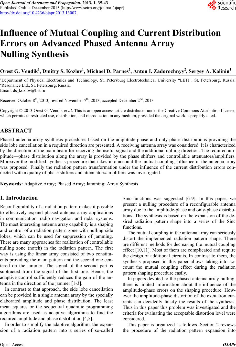 Open Journal of Antennas and Propagation, 2013, 1, 35-43 Published Online December 2013 (http://www.scirp.org/journal/ojapr) http://dx.doi.org/10.4236/ojapr.2013.13007 Open Access OJAPr 35 Influence of Mutual Coupling and Current Distribution Errors on Advanced Phased Antenna Array Nulling Synthesis Orest G. Vendik1, Dmitry S. Kozlov1, Michael D. Parnes2, Anton I. Zadorozhnyy2, Sergey A. Kalinin1 1Department of Physical Electronics and Technology, St. Petersburg Electrotechnical University “LETI”, St. Petersburg, Russia; 2Resonance Ltd., St. Petersburg, Russia. Email: ds_kozlov@list.ru Received October 8th, 2013; revised November 7th, 2013; accepted December 2nd, 2013 Copyright © 2013 Orest G. Vendik et al. This is an open access article distributed under the Creative Commons Attribution License, which permits unrestricted use, distribution, and reproduction in any medium, provided the original work is properly cited. ABSTRACT Phased antenna array synthesis procedures based on the amplitude-phase and only-phase distributions providing the side lobe cancellation in a required direction are presented. A receiving antenna array was considered. It is characterized by the direction of the main beam for receiving the useful signal and the additional nulling direction. The required am- plitude—phase distribution along the array is provided by the phase shifters and controllable attenuators/amplifiers. Moreover the modified synthesis procedure that takes into account the mutual coupling influence in the antenna array was proposed. Finally the radiation pattern transformation under the influence of the current distribution errors con- nected with a quality of phase shifters and attenuators/amplifiers was investigated. Keywords: Adaptive Array; Phased Array; Jamming; Array Synthesis 1. Introduction Reconfigurability of a radiation pattern makes it possible to effectively expand phased antenna array applications in communication, radio navigation and radar systems. The most interesting antenna array capability is a shaping and control of a radiation pattern zone with nulling side lobes, which can be used for suppression of jamming. There are many approaches for realization of controllable nulling zone (notch) in the radiation pattern. The first way is using the linear array consisted of two constitu- ents providing the main pattern and the second one cen- tered on the jammer. The signal of the second part is subtracted from the signal of the first one. Hence, the adaptive control sufficiently reduces the gain of the an- tenna in the direction of the jammer [1-3]. In contrast to that approach, the side lobe cancellation can be provided in a single antenna array by the specially elaborated amplitude and phase distribution. The least mean squares or the sequential quadratic programming algorithms are used as adaptive algorithms to find the required amplitude and phase distribution [4,5]. In order to simplify the adaptive algorithm, the expan- sion of a radiation pattern into a series of so-called Sinc-functions was suggested [6-9]. In this paper, we present a nulling procedure of a reconfigurable antenna array due to the amplitude-phase and only-phase distribu- tions. The synthesis is based on the expansion of the de- sired radiation pattern shape into a series of the Sinc functions. The mutual coupling in the antenna array can seriously distort the implemented radiation pattern shape. There are different methods for decreasing the mutual coupling effect [10,11]. Most of them are complicated and require the design of additional circuits. In contrast to them, the synthesis proposed in this paper allows taking into ac- count the mutual coupling effect during the radiation pattern shaping procedure easily. In papers devoted to the phased antenna array nulling, there is limited information about the influence of the amplitude-phase errors on the shaping procedure. How- ever the amplitude-phase distortion of the excitation cur- rents can decidedly falsify the results of the synthesis. Thus in this paper this problem was investigated and the criteria for evaluating the acceptable distortion level were considered. This paper is organized as follows. Section 2 reviews the procedure of the radiation pattern expansion into 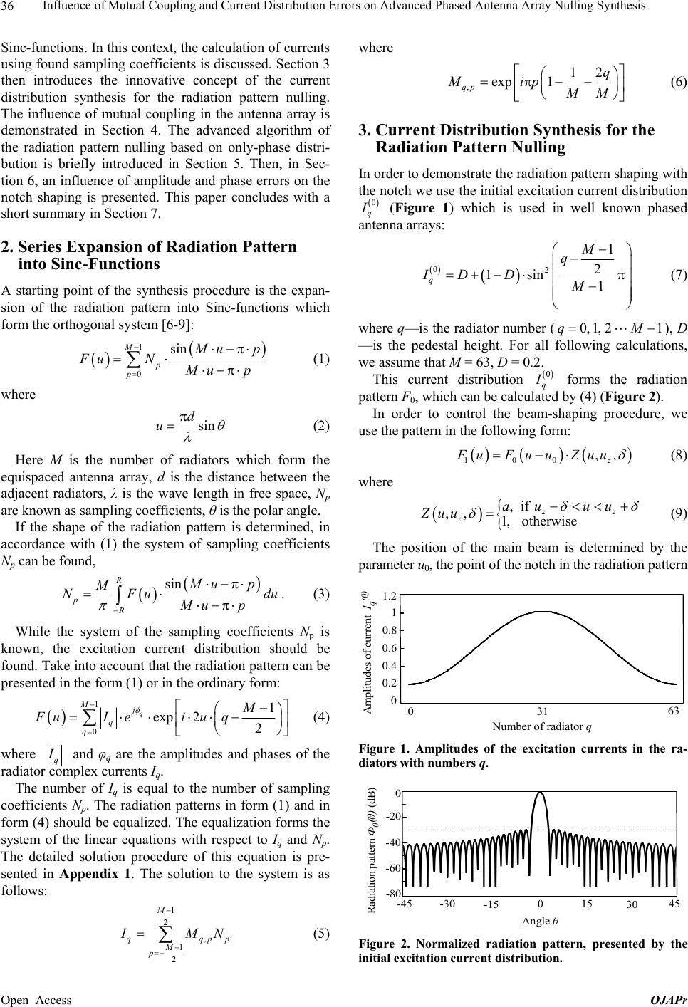 Influence of Mutual Coupling and Current Distribution Errors on Advanced Phased Antenna Array Nulling Synthesis 36 Sinc-functions. In this context, the calculation of currents using found sampling coefficients is discussed. Section 3 then introduces the innovative concept of the current distribution synthesis for the radiation pattern nulling. The influence of mutual coupling in the antenna array is demonstrated in Section 4. The advanced algorithm of the radiation pattern nulling based on only-phase distri- bution is briefly introduced in Section 5. Then, in Sec- tion 6, an influence of amplitude and phase errors on the notch shaping is presented. This paper concludes with a short summary in Section 7. 2. Series Expansion of Radiation Pattern into Sinc-Functions A starting point of the synthesis procedure is the expan- sion of the radiation pattern into Sinc-functions which form the orthogonal system [6-9]: 1 0 sin M p p M up Fu N M up (1) where sin d u (2) Here M is the number of radiators which form the equispaced antenna array, d is the distance between the adjacent radiators, λ is the wave length in free space, Np are known as sampling coefficients, θ is the polar angle. If the shape of the radiation pattern is determined, in accordance with (1) the system of sampling coefficients Np can be found, sin R p R Mu p M NFu Mu p du . (3) While the system of the sampling coefficients Np is known, the excitation current distribution should be found. Take into account that the radiation pattern can be presented in the form (1) or in the ordinary form: 1 0 1 exp 22 q Mj q q M FuIei u q (4) where q I and φq are the amplitudes and phases of the radiator complex currents Iq. The number of Iq is equal to the number of sampling coefficients Np. The radiation patterns in form (1) and in form (4) should be equalized. The equalization forms the system of the linear equations with respect to Iq and Np. The detailed solution procedure of this equation is pre- sented in Appendix 1. The solution to the system is as follows: 1 2 , 1 2 M qq M p where , 12 exp 1 qp q Mip MM (6) 3. Current Distribution Synthesis for the Radiation Pattern Nulling In order to demonstrate the radiation pattern shaping with the notch we use the initial excitation current distribution 0 q I (Figure 1) which is used in well known phased antenna arrays: 02 1 2 1sin 1 q M q ID DM (7) where q—is the radiator number (), D —is the pedestal height. For all following calculations, we assume that M = 63, D = 0.2. 0, 1,21qM This current distribution 0 q I forms the radiation pattern F0, which can be calculated by (4) (Figure 2). In order to control the beam-shaping procedure, we use the pattern in the following form: 100 ,, z FuFu uZuu (8) where ,if ,, 1, otherwise z z au uu Zuu z (9) The position of the main beam is determined by the parameter u0, the point of the notch in the radiation pattern 031 63 1.2 1 0.2 0.4 0.6 0 Number of radiator q Amplitudes of current I q ( 0 ) 0.8 Figure 1. Amplitudes of the excitation currents in the ra- diators with numbers q. -45 -30 0 15 45 30 -15 Angle θ 0 -60 -40 -20 -80 Rad ia tio n pattern Ф 0 ( θ ) (dB) pp I MN (5) Figure 2. Normalized radiation pattern, presented by the initial excitation current distribution. Open Access OJAPr  Influence of Mutual Coupling and Current Distribution Errors on Advanced Phased Antenna Array Nulling Synthesis 37 pattern is determined by uz, determines only the width of the notch and does not affect the notch position. The notch depth ξ measured from 0-dB level is characterized by the parameter a. If a = 1, there is no notch. If a < 0, the phase of the given pattern is modulated as well. This change of the phase in the given radiation pattern leads to a relevant perturbation of the current distribution along the antenna array. It is important to stress that the position of the notch and the position of the main beam are independent and determined separately by the parameters u0 and uz. The amplitude and phase distribution I q I and I q in a linear array can be found using (3) and (5) (Figures 3 and 4). Substitution the calculated values of the amplitude and phase distribution I q I and I q in (4) gives the radiation pattern 1 shown in Figure 5. 0 31 63 1.2 1 0.2 0.4 0.6 0 Number of radiator q Amplitudes of current I q(1) 0.8 Figure 3. Amplitudes of the currents in the radiators with numbers q for the case of side lobe cancellation in the re- quired direction. 0 31 63 3 2 -2 -1 0 -3 Number of radiator q 1 Phase of current φq(1) Figure 4. Phases (in degrees) of the currents in the radiators with numbers q for the case of side lobe cancellation in the required direction. -45 -30 0 15 45 30 -15 Angle θ 0 -60 -40 -20 -80 Radiation pattern Ф 1 (θ) (dB) Figure 5. Normalized radiation pattern with the fixed posi- tions of the notch θz and the main beam θ0 (θ0 = 0˚, θz = −20˚; = 2˚, a = −2, M = 63). The simplified scheme of adaptive antenna array with capability of nulling side lobes using amplitude-phase distribution is shown in Figure 6. It consists of the ra- diators—1, the sets of attenuators/amplifiers—2 and phase shifters—3, and the power divider—4. The power divider determines the initial current distribution. At- tenuators/amplifiers and phase shifters are used for ad- justment of amplitudes and formation of required phase shifts correspondingly. Both the phase shifters and am- plifiers are operating in analog regime providing a cor- rected linear connection between the bus data impacts and the actual phase and amplitude in the elements of the phased antenna array [12]. 4. Using Influence of the Mutual Coupling in the Antenna Array on the Radiation Pattern Shaping The procedure of the radiation pattern shaping presented in the section III was considered for the ideal case when the mutual coupling between radiators in the array is absent. Actually the mutual coupling in the antenna array can be sufficiently strong. In this case the radiation pattern shape can be seriously distorted. That is why the mutual coupling effect should be taken into account during the radiation pattern shaping procedure. The first step is calculating the impedance matrix Z of antenna array [11,13]. The mutual coupling between the radiators chosen as half-wave dipoles is described. For simplicity, we consider the coupling between each radiator and its two nearest neighbors, spaced at the distance of d and 2d correspondingly. As previously described, the divider forms the current distribution 0 q I (7). One can express the mutual coupling relationship as an impedance matrix relating the radiator currents to the applied voltages. 0 q UZI 0 q (10) where Z is the impedance matrix, are the applied voltages and 0 q U 0 q I are the complex amplitudes of the current distribution, as noted above. The radiation pattern shaped by is equivalent to the radiation pattern that formed by the current distribution 0 q U Figure 6. Antenna array controlling system. Drawing sym- bols: (1) radiators, (2) attenuators/amplifiers of different channels, (3) phase shifters, (4) power divider. Open Access OJAPr  Influence of Mutual Coupling and Current Distribution Errors on Advanced Phased Antenna Array Nulling Synthesis 38 distribution 00 11 m qq I UY , where Y11 is the admit- tance of a single radiator. Thereby, we can say that the presence of coupling between radiators leads to trans- formation of the current distribution 0 q I into the new one 0 q I , which is calculated as: 0m 11qq 0 I ZI Y (11) Letter “m” in the superscript accounts for the mutual coupling between radiators. Now we suggest performing the synthesis procedure presented in Section 2 of the paper. After replacing 0 q I by 0m q I in all subsequent calculations (1)-(5) one obtains the radiation pattern 2 (Figure 7). One should compare Figure 2 and Figure 7 realizing that these radiation patterns have been simulated with and without taking into account the mutual coupling between radiators. The next step refers to the synthesis of current dis- tribution m q I , which provides the side lobe cancellation in the specified direction. Taking into account the mutual coupling between radiators, one obtains the current dis- tribution 1m q I , that should be set after the attenuators/ amplifiers and the phase shifters: 11 11 m qq I ZI Y (12) The current distribution 1m q I found in this way shapes the radiation pattern 3 (Figure 8). After that the transfer coefficients m q K (Figure 9) and the phases m q (Figure 10) can be found: 1 0 m q m q q I K I (13) 1 arg m qq I m m (14) The transfer coefficients q K and the phases m q should be used to control the operation of the amplifiers/ attenuators and the phase shifters. As it is shown, the mutual coupling in the antenna array demands the sufficient correction of the amplitude and phase distribution of the radiator currents. After that -45 -30 0 15 45 30 -15 Angle θ 0 -40 -20 -60 Radiation pattern Ф2(θ) (dB) Figure 7. Normalized radiation pattern, presented by the initial excitation current distribution with mutual coupling influence. -45 -30 0 15 45 30 -15 An g le θ 0 -40 -20 -60 Radiation pattern Ф 3 (θ) (dB) Figure 8. Normalized radiation pattern with mutual cou- pling influence with the fixed positions of the notch θz and the main beam θ0 (θ0 = 0˚, θz = −20˚; = 2˚, a = −2, M = 63). 031 63 1.5 1.4 1.0 1.1 1.2 0.9 Number of radiator q Transfer Coefficient K q(m) 1.3 Figure 9. Transfer coefficients of the attenuators/amplifiers for the case of side lobe cancellation in the required direc- tion with mutual coupling influence. 0 31 63 -10 0 -20 Number of radiator q 10 20 Phase φ q (m) Figure 10. Phases of the phase shifters with numbers q for the case of side lobe cancellation in the required direction. correction the notch form is weakly affected. Thus, it can be assumed that the proposed radiation pattern shaping procedure with the side lobe cancellation is more or less stable with respect to the mutual coupling effect. 5. Radiation Pattern Nulling by Only-Phase Distribution The shaping synthesis of the radiation pattern with the notch in the required direction was presented in the previous sections of this paper. The proposed procedure requires a modification of the phase and amplitude distribution along the antenna array. This fact leads to using additional attenuators/amplifiers that result in the complication of the whole system. For this reason it was proposed to use the initial amplitude distribution and change only the phase distribution along the array Open Access OJAPr  Influence of Mutual Coupling and Current Distribution Errors on Advanced Phased Antenna Array Nulling Synthesis 39 according to the described synthesis. Thus the final radiation pattern is determined as: 1 10 2 0 1 exp 22 q Mj q q M FuIei u q (15) where 0 q I —the initial current distribution along the antenna array and I q —the phase distribution obtained by calculations according the synthesis procedure. The radiation pattern shaped by proposed method is presented in Figure 11. In this case the position and the depth of the notch are not changed, but the additional “upsurge” is appeared. It should be noted that the correlation between the depth of the notch and the height of the “upsurge” can be varied. In this paper we chose settings to get the suffi- ciently large depth of the notch. In this case, the height of the “upsurge” is about 6 dB above the level of the side lobes. Thus, two shaping procedures: amplitude-phase and only-phase distribution were compared. Amplitude-phase synthesis allows obtaining a more equable radiation pat- tern without “upsurge”. However in this case the radia- tion pattern control system is more complicate because the additional set of the attenuators/amplifiers is required. If we use this synthesis procedure based on the only- phase distribution the set of attenuators/amplifiers can be deleted. 6. Influence of Amplitude and Phase Errors on Formation of Notch in the Radiation Pattern The procedure of the antenna array synthesis presented above was considered for the case of the amplitude-phase current distribution along the array without distortion. In reality, the amplitude-phase distribution will be distorted due to various errors. In this section the distortion of the original radiation pattern under the influence of errors will be considered. The level of errors depends on the quality of the phase shifters, attenuators/amplifiers and power divider. -45 -30 0 15 45 30 -15 Angle θ 0 -60 -40 -20 -80 Radiation pattern Ф 4 (θ) (dB) Figure 11. Normalized radiation pattern with the fixed po- sitions of the notch θz and the main beam θ0 shaped by only-phase distribution synthesis (θ0 = 0˚, θz = −20˚; = 2˚, a = −2, M = 63). The current distribution is found as a result of synthe- sis: the amplitude Iq and the phase φq do not contain er- rors. The current and phase distribution with errors can be determined by the following equations: errorqq II q I q (16) errorqq (17) where q I and q are the amplitude and phase errors of complex currents of the radiators. The errors q I и q are in the range [max , ] and [maxq q Imaxq I , maxq ], where max and maxqq I I are the maximum deviation of Iq и φq. Values q и q are random numbers which are allocated within the range determined above. The set of the random numbers was found by using a built-in MathCAD function rnd(x) [14]. The selected pattern parameters (θ0, θz, δ, a, M) are presented in Figures 5 and 11. The errors q I and q are randomized. Now we should find the statistical characteristics of the notch parameters. Thereto principles of the probability theory [15] should be used. Let us consider variety of depth of the notch ξ for randomized pairs of errors q I and q . For hundred pair of q I and q the values of depth of the notch have been found. The set of the values of depth of the notch is named as a sampling. In the case considered firstly one obtains the random samples (1 2100 , ). The next step is formation of nondecreasing sequence (12100 ), which is characterized by transposed numbers of the sequence. Such a nondecreasing sequence is named as a variation series. The graphical presentation of the variation series as a function of the transposed numbers of the selected pairs and q Iq is pre- sented in Figure 12. The variation series is used to construct the empirical distribution function (see Appendix 2). The empirical distribution function may be named as a probability P for obtaining the maximum notch depth ξ. The simulation of P is worked out for the set of maxq , which are equal to 0.1˚, 0.3˚, 0.5˚, 1.0˚, 2.0˚, and 4.0˚ respectively, for the case of maximum ampli- tude error max 0.2 dB q I (Figure 13(a)) and for the for the set of maximum amplitude errors 0.1, 0.2, 0.3, 0.4, Notch Depth ξ (dB) Number n 0 -80 50 0 -40 20 40 10 30 Figure 12. Graphical presentation of variation series. Open Access OJAPr  Influence of Mutual Coupling and Current Distribution Errors on Advanced Phased Antenna Array Nulling Synthesis 40 0.5, 0.6 dB in the case of maximum phase error 1.0 de- gree (Figure 13(b)). The probability P as a function of the notch depth was used for a simulation of the expectation value of the notch depth maxq, which is presented as a function of the maximum of the phase error M maxq , for maxq ( Figure 14(a)) and as a function of amplitude errors for 0.2 dIB maxq Imax 1degree q ( Fig- ure 14(b)). As one can see from Figure 14 the increasing the error is followed by the decreasing the modulus of the notch depth. The probability P as a function of the notch depth was used for a simulation of the dispersion of the notch depth , which is presented as a function of the maximum error maxq D maxq , for maxq I 1degree maxq ( Figure 15(a)) and and as a function of the maximum amplitude error for 0.2 dIB maxq (Figure 15(b)). Dispersion is a measure of deviation of the considered value (the notch depth ξ) from the expectation value . In some approximation, the dispersion can be considered as a width of the notch. The estimation of the notch widths from Figure 15(a) and (b) is about 4 - 5 dB, that is in agreement with notch widths presented in Figures 5 and 11. maxq M The simulation of expectation values and dispersions of notch are explained in Appendix 2. Probability P(ξ) Notch Depth ζ (dB) 1 0 -30 -90 0.5 -60 -45 -75 (a) Probability P(ξ) Notch Depth ζ (dB) 1 0 -40 -75 0.5 -60 -50 -70 (b) Figure 13. (a) Probability distribution functions for the maximum amplitude error 0.2 dB and for maximum phase errors 0.5, 1, 2 degree; (b) Probability distribution functions for the maximum phase error 1 degree for maximum am- plitude errors 0.1, 0.2, 0.4 dB. Notch Depth ξ (dB) Phase error ( de g ree ) -40 -60 2.5 0 -50 12 0.5 1.5 onl y - p hase amplitude-phase (a) Notch Depth ξ (dB) Amplitude error (dB) -40 -60 0.5 0 -50 0.2 0.4 0.1 0.3 onl y -phase amplitude-pha se (b) Figure 14. (a) Expectation value of the notch depth for the maximum amplitude error 0.2 dB for both types of control; (b) Expectation value of the notch depth for the maximum phase error 1 degree for both types of control. Notch Depth ξ (dB) Phase error ( de g ree ) 6 02.5 0 3 12 0.5 1.5 only-phase amplitude-phase (a) Notch Depth ξ (dB) Amplitude error (dB) 6 00.5 0 3 0.2 0.4 0.1 0.3 onl y - p hase am p litude- p hase (b) Figure 15. (a) Dispersion of the notch depth for the maxi- mum amplitude error 0.2 dB for both types of control; (b) Dispersion of the notch depth for the maximum phase error 1 degree for both types of control. Application of this analysis for taking into account the error effect on the radiation pattern nulling makes it possible to formulate the requirements for the precision Open Access OJAPr  Influence of Mutual Coupling and Current Distribution Errors on Advanced Phased Antenna Array Nulling Synthesis Open Access OJAPr 41 of phased antenna array control system. 7. Conclusion The synthesis of an adaptive antenna array has been de- scribed. This procedure allows controlling the direction of the main beam for receiving the useful signal and the direction of the notch independently. Practical applica- tion of the expansion of a reconfigurable radiation pat- tern into a series of the Sinc functions has been newly described. This procedure which was additionally modi- fied allowing taking into account the mutual coupling influence in the antenna array was proposed. It was de- monstrated that in this case the notch forming does not distort significantly under the mutual coupling influ- ence. 8. Acknowledgements This work was initiated and supported by company “Resonance Ltd.”, Saint Petersburg. REFERENCES [1] S. P. Appelbaum, “Adaptive Arrays,” IEEE Transactions on Antennas and Propagation, Vol. 24, No. 5, 1976, pp. 585-598. http://dx.doi.org/10.1109/TAP.1976.1141417 [2] R. A. Monzingo and T. W. Miller, “Adaptive Arrays,” John Wiley and Sons, New York, 1980. [3] R. J. Mailloux, “Phased Array Antenna Handbook,” Artech House, Boston, London, 1994. [4] Y. Chu and W.-H. Fang, “A Novel Wavelet-Based Gen- eralized Side Lobe Canceller,” IEEE Transactions on An- tennas and Propagation, Vol. 47, No. 9, 1999, pp. 1485- 1494. http://dx.doi.org/10.1109/8.793330 [5] M. Mouhamadou and P. Vaudon, “Smart Antenna Array Patterns Synthesis: Null Steering and Multu-User Beam Forming by Phase Control,” Progress in Electromagnet- ics Research, PIER, Vol. 60, 2006, pp. 95-106. http://dx.doi.org/10.2528/PIER05112801 [6] P. M. Woodward, “A Method of Calculating the Field over a Plane Aperture Required to produce a Given Polar Diagram,” Journal I.E.E. (London), Vol. 93, 1947, Part IIIA, pp. 1554-1558. [7] P. M. Woodward and J. D. Lawson, “The Theoretical Precision with Which an Arbitrary Radiation-Pattern May Be Obtained from a Source of Finite Size,” Journal of the Institution of Electrical Engineers—Part III: Radio and Communication Engineering, Vol. 95, No. 37, 1948, pp. 363-370. [8] O. G. Vendik, “Synthesis of a Line Antenna Array with Non-Mechanical Scanning,” Izvestiya Vuzov: Radiotech- nika, No. 1, 1960, pp. 77-86. (in Russian) [9] O. G. Vendik and D. S. Kozlov, “Phased Antenna Array with a Side Lobe Cancellation for Suppression of Jam- ming,” IEEE Antennas and Wireless Propagation Letters, Vol. 11, 2012, pp. 648-650. http://dx.doi.org/10.1109/LAWP.2012.2203780 [10] C. A. Balanis, “Antenna Theory: Analysis and Design,” John Wiley & Sons Inc., New York, 2005. [11] B. H. Wang and H. T. Hui, “Wideband Mutual Coupling Compensation for Receiving Antenna Arrays Using the System Identification Method,” IET Microwaves, Anten- nas and Propagation, Vol. 5, No. 2, 2011, pp. 184-191. http://dx.doi.org/10.1049/iet-map.2010.0120 [12] A. I. Zadorozhnyy, “C-Band 360˚ Digitally-Controlled Analog Phase Shifter with Low Amplitude Modulation Value,” Antennas: Radiotechnika, Vol. 10, 2012, pp. 11- 15. (in Russian) [13] J. L. Masa-Campos and J. M. Fernadez, “Coupling Char- acterization and Compensation Model for Antenna Ar- rays,” Journal of Microwave and Optoelectronics, Vol. 4, No. 2, 2005. [14] www.mathcad.com [15] D. Stirzaker, “Elementary Probability,” Cambridge Uni- versity Press, Cambridge, 2003. http://dx.doi.org/10.1017/CBO9780511755309  Influence of Mutual Coupling and Current Distribution Errors on Advanced Phased Antenna Array Nulling Synthesis 42 Appendix 1 For finding the matrix Mq,p the radiation patterns in form (1) and in form (4) should be equalized: 11 00 sin 1 exp 22 MM qp qp M up M Iiuq N M up , We can multiply the left and right sides of the equation by exp21 2iuq M and then integrate with respect to u in the range of –Rπ to Rπ. (R is integer) The left part of the equation has the following form: 1 0 1 exp 2exp2 22 RM q q R M1M I iuqiuq du , (19) The right part of the equation has the following form: 1 0 sin 1 exp 22 R M p pR Mu pM Niuq Mu p du , (20) The functions exp included in the Equation (19) form the orthogonal system: 2if exp exp0if R R Rlm iuliumdu lm , (21) So the left part can be simplified and the initial equation will be transformed: 1 0 sin 1 exp 22 R M qp pR Mu pM I Niuq Mu p du , (22) The main task is integration of the integral in the Equation (22). The function exp can be expanded by sincos functions. Thus the required integral is represented as the sum of two simpler integrals: sin 1 exp 2 π2 sin 1 cos 2sin2 22 R RR R Mu p MM iuq du Mu p Mu p MM uqi uqdu Mu p 1 M , (23) The approximate solutions of these integrals are: 11 sin 1cos 2if cos 222 π20otherwise R R 2 M pM Mu p MM qq uq duM Mu p M , (24) 11 sin 1sin 2if sin 222 π20otherwise R R 2 M pM Mu p MM qq uq duM Mu p M , (25) Finally: sin 11 exp 2exp 2exp1 22 R R Mu p12 M MMp iuqdui qip MupMM M q , (26) The solution accuracy depends on the limits of integration (i.e., the parameter R) and the number of radiators M. It was proposed to estimate the solution accuracy by using the standard deviation : 2 21 ,, pq fqpfqp M , (27) where Open Access OJAPr  Influence of Mutual Coupling and Current Distribution Errors on Advanced Phased Antenna Array Nulling Synthesis Open Access OJAPr 43 1 sin 1 (, )exp22 R R Mu p MM f qpi u qdu Mu p (28) 2 12 1 exp 1if (, )2 0otherwise qM ip q fqp MM 2 M (29) The simulation results as ,RM are given in the table: Table 1. Table type styles. M R 5 15 25 55 1 0.175 0.165 0.162 0.16 3 0.06 0.056 0.055 0.054 5 0.035 0.033 0.033 0.032 10 0.018 0.017 0.016 0.016 It can be seen that the number of radiators effects not as strong as the integration limits. The deviations are less than 2% for the value of R more than 10. Such accuracy is enough. Appendix 2 In Section 4 the construction of the variation series was described. The series is used to construct the empirical distribution function: m Pn , (30) where mξ is number of terms in series which is smaller than ξ. In the case considered n = 100. The variation series (ξk) can be used for calculation of the sample average, which can be considered as an empirical expectation value of ξ (maximum notch depth) as a function of the maximum deviation of max I or max (see Figure 14): max max 1 1 , n k k MI n . (31) The variation series (ξk) can be used for calculation of the sample standard deviation, which can be considered as a square root from an empirical dispersion for the maximum deviation of ξ ( maximum notch depth) as a function of the maximum deviation max I or max (see Figure 15): 2 max max 1 1 , n k k DI n . (32) |