Open Journal of Civil Engineering, 2013, 3, 228-233
Published Online December 2013 (http://www.scirp.org/journal/ojce)
http://dx.doi.org/10.4236/ojce.2013.34027
Open Access OJCE
Influence of the Elastic Modulus of the Soil and Concrete
Foundation on the Displacements of a Mat Foundation
Oustasse Abdoulaye Sall1*, Meissa Fall1, Yves Berthaud2, Makhaly Ba1
1Département Génie Civil, UFR SI-Université de Thiès, Thiès, Sénégal
2UFR Ingénierie, Université Pierre et Marie Curie, Paris, France
Email: *oustaz.sall@univ-thies.sn
Received November 20, 2013; revised December 12, 2013; accepted December 19, 2013
Copyright © 2013 Oustasse Abdoulaye Sall et al. This is an open access article distributed under the Creative Commons Attribution
License, which permits unrestricted use, distribution, and reproduction in any medium, provided the original work is properly cited.
ABSTRACT
In this paper, we suggest to study the behavior of a mat foundation on subsoil from the plate theory taking into account
the soil-structure interaction. The objective is to highlight the soil-structure interaction particularly the influence of the
rigidities of the soil and the concrete on the subgrade reaction (k) and the displacements of the mat foundation subjected
to vertical loads. From plate theory and the soil-structure interaction, the general equation is reached. This equation de-
pends more on the subgrade properties than the concrete foundation properties. Consequently, the behavior of the mat
foundation is more influenced by soil properties than the concrete.
Keywords: Mat Foundation; Plate Theory; Soil-Structure Interaction; Mechanical Properties
1. Introduction
The structural and geotechnical calculations of civil en-
gineering works involve the limit state method and re-
quire the determination of characteristic values for resis-
tance and deformation criteria of structures and soils.
However, the geotechnical design is mainly based on the
determination of the displacement caused by the actions
applied to foundation and the determination of stresses
under limit state service. The structural design is strongly
based on the determination of stresses and displacements.
A computational approach that takes into account struc-
tural and geotechnical aspects related to the design of
foundation structures must be developed. It is then ques-
tion of interaction between two bodies of very different
characteristics of deformability. The rupture is often fol-
lowed by the formation of a thin region led in the direc-
tion of contact. This area is called soil-structure interface
and it is the location of the major displacements. This
work focused on the foundation slab and, more particu-
larly, on the characterization of the soil-structure inter-
face. A precise knowledge of moduli characterizes its
deformability and stress paths which should facilitate the
optimization of the structural and geotechnical design of
foundation.
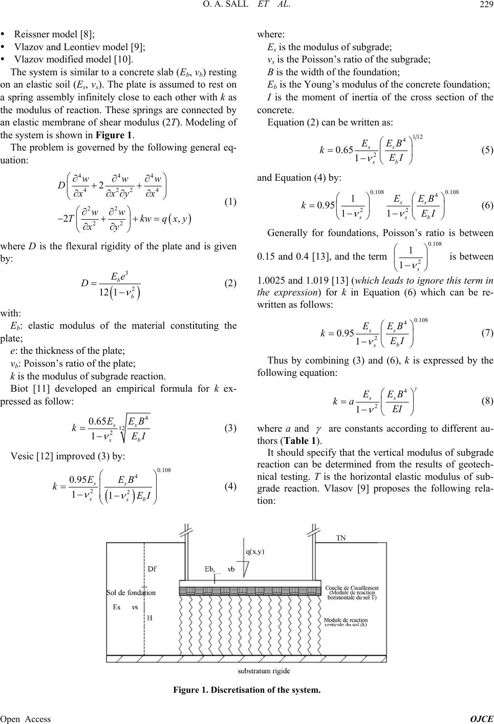
2. Modelisation
A foundation is responsible for transmitting the loads
from the superstructure to the soil; it provides an inter-
face between the upper part of the structure and the soil.
A mat foundation is a continuous reinforced concrete
slab and the study may be governed by the theory of
plates whose behavior can be studied from the Lagrange
equation which take into account the soil-structure inter-
action. The solution of the Lagrange equation is possible
with the use of the methods of Fourier series or finite
differences with well-defined boundary conditions. Cha-
racterization of the interface has also allowed us to see
that the soil-structure interaction is important for the de-
sign of foundation. Selvadurai [1] presented a detailed
analysis of the soil-foundation interaction problem, ex-
plaining the different approaches proposed to model this
interaction. These models recognize that soil reaction is a
linear function of the displacement of the soil-founda-
tion interface layer. Several models have been devel-
oped:
Winkler model [2],
Elastic continuum model [1];
Biparametric model [3];
Filonenko Borodich model [4,5];
Hetenyi model model [6];
*Corresponding author.
Pasternak model [7];