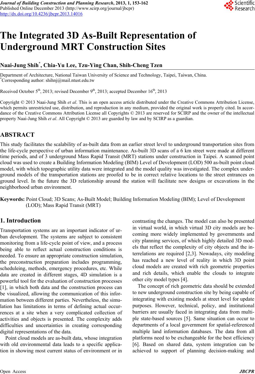
 Journal of Building Construction and Planning Research, 2013, 1, 153-162 Published Online December 2013 (http://www.scirp.org/journal/jbcpr) http://dx.doi.org/10.4236/jbcpr.2013.14016 Open Access JBCPR 153 The Integrated 3D As-Built Representation of Underground MRT Construction Sites Naai-Jung Shih*, Chia-Yu Lee, Tzu-Ying Chan, Shih-Cheng Tzen Department of Architecture, National Taiwan University of Science and Technology, Taipei, Taiwan, China. *Corresponding author: shihnj@mail.ntust.edu.tw Received October 5th, 2013; revised December 9th, 2013; accepted December 16th, 2013 Copyright © 2013 Naai-Jung Shih et al. This is an open access article distributed under the Creative Commons Attribution License, which permits unrestricted use, distribution, and reproduction in any medium, provided the original work is properly cited. In accor- dance of the Creative Commons Attribution License all Copyrights © 2013 are reserved for SCIRP and the owner of the intellectual property Naai-Jung Shih et al. All Copyright © 2013 are guarded by law and by SCIRP as a guardian. ABSTRACT This study facilitates the scalability of as-built data from an earlier street level to underground transportation sites from the life-cycle perspective of urban information maintenance. As-built 3D scans of a 6 km street were made at different time periods, and of 3 underground Mass Rapid Transit (MRT) stations under construction in Taipei. A scanned point cloud was used to create a Building Information Modeling (BIM) Level of Development (LOD) 500 as-built point cloud model, with which topographic utility data were integrated and the model quality was investigated. The complex under- ground models of the transportation stations are proofed to be in correct relative locations to the street entrances on ground level. In the future the 3D relationship around the station will facilitate new designs or excavations in the neighborhood urban environment. Keywords: Point Cloud; 3D Scans; As-Built Model; Building Information Modeling (BIM); Level of Development (LOD); Mass Rapid Transit (MRT) 1. Introduction Transportation systems are an important indicator of ur- ban development. The systems are subject to consistent monitoring from a life-cycle point of view, and a process being able to reflect actual construction conditions is needed. To ensure an appropriate construction simulation, the preconstruction preparation includes programming, scheduleing, methods, emergency procedures, etc. While data are created in different stages, 4D simulation is a powerful tool for the evaluation of construction processes [1], in which both data and the construction process can be visualized, allowing the communication of this infor- mation between different parties. Nevertheless, the simu- lation has limitations in terms of defining actual occur- rences at a site when a very complicated collection of activities and objects is presented. The complexity adds difficulties and uncertainties in creating corresponding digital representations of the data. Point cloud models are as-built data, whose integration with old environmental data leads to a specific applica- tion in showing most current status of environment or in contrasting the changes. The model can also be presented in virtual world, in which virtual 3D city models are be- coming more widely implemented by governments and city planning services, of which highly detailed 3D mod- els that reflect the complexity of city objects and the in- terrelations are required [2,3]. Nowadays, city modeling has reached a new level of reality in which 3D point cloud models are created with rich geometric properties and rich details, which enable the clouds to integrate other city model types [4]. The concept of rich geometric data should be extended to new underground construction site by being capable of integrating with existing models at street level for update purposes. However, technical, policy, and institutional barriers are usually faced in integrating data from multi- ple state-based sources [5]. Same situation can occur to departments of a local government for spatial-referenced multiple land information databases. The data from all platforms need to be exchangeable for the best efficiency [6]. Based on shared data, system integration can be achieved to support of planning decision-making and 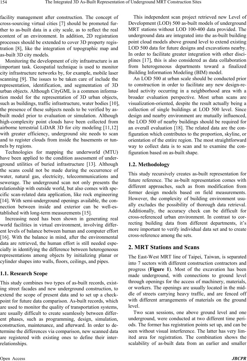 The Integrated 3D As-Built Representation of Underground MRT Construction Sites 154 facility management after construction. The concept of cross-sourcing virtual cities [7] should be promoted fur- ther to as-built data in a city scale, as to reflect the real content of an environment. In addition, 2D registration processes should be extended to cover 3D property regis- tration [8], like the integration of topographic map and as-built 3D city models. Monitoring the development of city infrastructure is an important task. Geospatial technique is used to monitor city infrastructure networks by, for example, mobile laser scanning [9]. The issues to be taken care of include the representation, identification, and segmentation of 3D urban objects. Although CityGML is a common informa- tion model for the representation of 3D urban objects, such as buildings, traffic infrastructure, water bodies [10], the presence of these subjects needs to be verified by as- built model prior to evaluation or simulation. Although high-complexity point clouds have been collected from airborne terrestrial LiDAR 3D for city modeling [11,12] with greater efficiency, underground site needs to scan and to register clouds from inside the basements or tun- nels by regions. Technologies for mapping the underworld (MTU) have been applied to the condition assessment of under- ground utilities of buried infrastructure [13]. Although the scans could not be made during the occurrence of water, natural gas, electricity, telecommunications and sewerage. The underground scan not only presents the relationship with outside world, but also comes with spe- cific scan-related data application, like rock engineering [14]. With semi-underground openings available, the con- nection between inside and exterior can be well-es- tablished with long-term measurements [15]. Increasing need has been shown in generating real world facilities in virtual environment, involving differ- ent levels of balance between human and computer effort [16]. With the balance in mind, after the environmental data are retrieved, the human effort is still needed espe- cially in identifying the difference between heterogeneous representations among objects by initializing planar or cylinder shapes into walls, floors, ceilings, and pipes. 1.1. Research Scope This study combines two types of as-built records, exist- ing street facades and new underground construction, to extend the scope of present data and to set up a check- point for future data comparison. As-built records, which are used to monitor the quality of transportation systems, are usually difficult to create seamlessly between differ- ent phases, such as programming, design, simulation, construction, maintenance, and afterward. In order to de- termine the differences via comparison, new scanned data are registered with existing ones to define their inter- relationships. This independent scan project retrieved new Level of Development (LOD) 500 as-built models of underground MRT stations without LOD 100-400 data provided. The underground data are integrated into the as-built building point cloud models above ground level to extend existing LOD 500 data for future designs and excavations nearby. In order to facilitate greater integration with other disci- plines [17], this is also considered as data collaboration from heterogeneous departments toward a finalized Building Information Modeling (BIM) model. An LOD 500 at urban scale should be conducted prior to construction in order to facilitate any new design-re- lated activity occurring in a neighborhood area with a broader evaluation perspective. Most urban scans are visualization-oriented, despite the result actually being a collection of single buildings at LOD 500 level. Since design and nearby environment are mutually influenced, the LOD 500 of nearby buildings should be required for an overall evaluation [18]. The related data are the con- figuration which contributes to the proportion, skyline, or orientation of the entire region. The most straightforward way to collect data is to scan and to examine the con- figuration based on as-built shape. 1.2. Methodology This study recursively creates as-built representation for future reference. The as-built representation comes with different approaches, such as from modification from former design models based on field measurements. However, the complexity of building environment usu- ally excludes the possibility of thorough data retrieval. Additionally, the accuracy check can be difficult for cross-referenced urban environment. In contrast to cor- recting building data from different departments, it’s more important to verify individual data set and to create cross-reference among the sets. 2. MRT Stations and Scans The East-West MRT line of Taipei, Taiwan, is separated into 7 sectors with different construction contractors and progress (Figure 1). Most of the excavation has been made underground, with connections to ground level through openings for the access of machinery, materials, or workers. The openings are usually located in the mid- dle of streets carrying heavy traffic, and are fenced off with different arrangements of materials on the ground level. Two scan sessions, one above ground level and one underground, were conducted at two different time peri- ods. The former has registration points set up, and can be seen without visual interference. The latter has very lim- ited area for registration. The combination shows the scalability of as-built data from an earlier and smaller Open Access JBCPR 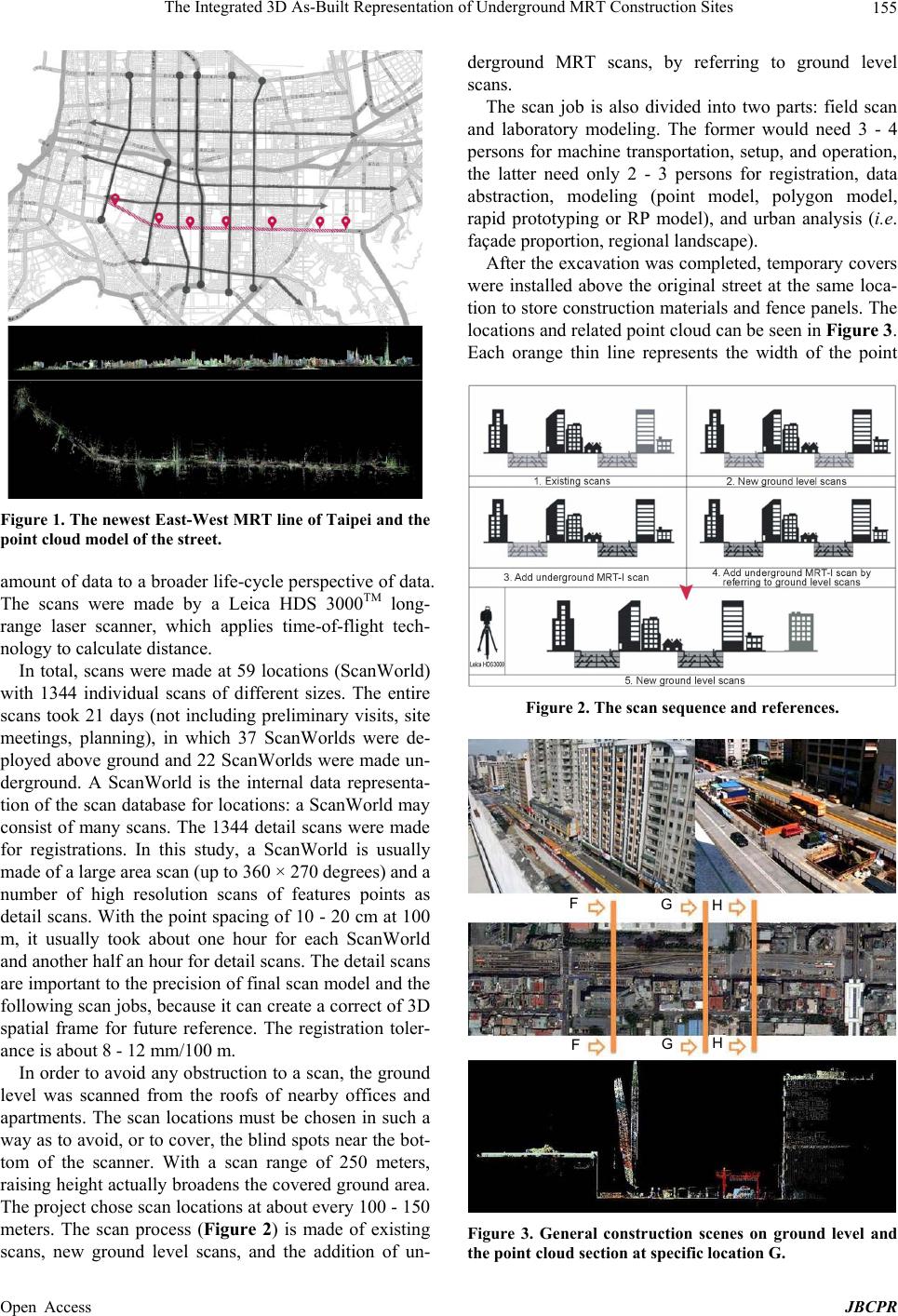 The Integrated 3D As-Built Representation of Underground MRT Construction Sites 155 Figure 1. The newest East-West MRT line of Taipei and the point cloud model of the street. amount of data to a broader life-cycle perspective of data. The scans were made by a Leica HDS 3000TM long- range laser scanner, which applies time-of-flight tech- nology to calculate distance. In total, scans were made at 59 locations (ScanWorld) with 1344 individual scans of different sizes. The entire scans took 21 days (not including preliminary visits, site meetings, planning), in which 37 ScanWorlds were de- ployed above ground and 22 ScanWorlds were made un- derground. A ScanWorld is the internal data representa- tion of the scan database for locations: a ScanWorld may consist of many scans. The 1344 detail scans were made for registrations. In this study, a ScanWorld is usually made of a large area scan (up to 360 × 270 degrees) and a number of high resolution scans of features points as detail scans. With the point spacing of 10 - 20 cm at 100 m, it usually took about one hour for each ScanWorld and another half an hour for detail scans. The detail scans are important to the precision of final scan model and the following scan jobs, because it can create a correct of 3D spatial frame for future reference. The registration toler- ance is about 8 - 12 mm/100 m. In order to avoid any obstruction to a scan, the ground level was scanned from the roofs of nearby offices and apartments. The scan locations must be chosen in such a way as to avoid, or to cover, the blind spots near the bot- tom of the scanner. With a scan range of 250 meters, raising height actually broadens the covered ground area. The project chose scan locations at about every 100 - 150 meters. The scan process (Figure 2) is made of existing scans, new ground level scans, and the addition of un- derground MRT scans, by referring to ground level scans. The scan job is also divided into two parts: field scan and laboratory modeling. The former would need 3 - 4 persons for machine transportation, setup, and operation, the latter need only 2 - 3 persons for registration, data abstraction, modeling (point model, polygon model, rapid prototyping or RP model), and urban analysis (i.e. façade proportion, regional landscape). After the excavation was completed, temporary covers were installed above the original street at the same loca- tion to store construction materials and fence panels. The locations and related point cloud can be seen in Figure 3. Each orange thin line represents the width of the point Figure 2. The scan sequence and references. FGH FGH Figure 3. General construction scenes on ground level and the point cloud section at specific location G. Open Access JBCPR  The Integrated 3D As-Built Representation of Underground MRT Construction Sites 156 cloud that the section is made of, and the arrows indicate the viewing direction. The steel supports have not been completed, and the excavation, construction materials, and small machinery were placed on the ground level. Part of the construction under ground level was uncov- sered during this scan period. Shin-I street is part of the main circulation system running East-West in Taipei. The MRT construction on street level and below has a significant impact on public transportation. The reduction of the original street width for excavation and temporary working decks intensifies traffic problems. To quantify the influence, the section at each interval is extracted to illustrate the percentage of construction over the entire street width for about 10% - 40%. Street profiles can vary according to buildings on both sides, and by construction-related activities. Large construction machinery, about two-stories high, is usu- ally installed next to ground openings close to the middle of the street, dividing the space in half. The section pro- files, which can also be seen in the point cloud (Figure 3), illustrate the narrow clearance between the machines and the facades. 2.1. Underground Construction of MRT Stations The MRT stations and rails are constructed beneath one of the main streets in Taipei. Although this concealed infrastructure is connected to the daily activity above, the relative locations of the two are very important, as the complexity may affect future construction or renovations. Considering the types of complexity three-dimensionally, three MRT stations were studied as 1) Type A: a joint design and development with a park at ground level; 2) Type B: shared structure with the existing MRT station; and 3) Type C: a typical underground station. Types A and B are exemplified in the following sections. Scans (Type A) were made at different locations, such as entrances, the ticket lobby and the platform (Figure 4). The scanned components included: structures, rails, tun- nels, materials, and HVAC systems. Additional scans were made to combine the cloud models above ground level. Retrieving sections at different locations of a cloud model helps in the comprehension of the construction process and the inter-relationships among components. The co-related component arrangement is more likely to uncover any missing interface between systems. The sections are directly made from the as-built cloud models; they are more likely to precisely react to construction errors. The cloud-derived plan (Figure 5) illustrates the locations of walls, columns, staircases and temporary storage areas. The platform can also be identified on the B2 level. The cross-section of the entire station shows the relative location of the steel structures of two floor levels and the temporary working platforms. Figure 4. Point clouds of entrance, platform, rails and steel structure. Figure 5. The point cloud of the urban environment at ground level and MRT under g r o und (Type A). 2.2. A Top-Down Hierarchy of Cloud Models A construction schedule consists of multiple concurrent or sequential activities. To record the entire perspective of the as-built 4D progress, the activities in terms of components have to be defined from, for example, tem- porary structures, excavation, foundation, steel bars, con- crete, rails, and steel structure, to interior finishing. The complexity in terms of details is traditionally defined in a bottom-up structure in which each type has to relate its presence in regard to the entire perspective. To simulate the structure in this way would require tremendous effort. In contrast, a top-down viewpoint in defining complex construction activities uses the cloud model as the central database and subdivides each construction as needed at each schedule checkpoint for inspection. From the design point of view, a building is the product of a top-down process. Thus, a building cloud model is defined from a construction record point of view, which is useful be- cause of its similar top-down nature. Most importantly, the cloud model is a feasible means of recovering the Open Access JBCPR  The Integrated 3D As-Built Representation of Underground MRT Construction Sites 157 geometric construction conditions at a certain level, compared to the limited perspective of photographs, videos, 2D drawings, or 3D design models, in which the data segmentation characteristics can hardly be related to each other; the as-built database possibly would not even exist unless scans are made. The point cloud can be navigated by users trained to read this specific type of data representation, and a pro- ject leader can also request the cloud be rotated, panned, or scaled, as needed, to look for a specific point as a ver- tex or a set of linear points as an edge for measurements. 3. Inspection of the Relationship between the MRT Station and the Urban Environment The as-built facades and cross-sections of a street are very difficult to create. Government infrastructure sur- veys refer to traditional field data. With private property buildings, the data of an entire street or block are not only difficult to integrate as a whole, but access to the data of each private building is usually restricted. Current 2D drawings have limited block-wise information in both vertical and horizontal dimensions, especially when deal- ing with all street-facing buildings. Due to a lack of up- dated information on new and old buildings, as-built data become the only source of information for any new con- struction project. 3D scans of an entire block and street enable the crea- tion of as-built data, which integrate not only various private buildings, but also the co-relationship between government and private sources of data. The integrated and co-related data enable the generation of various types of drawings [19], which eliminates the needs to visit a large number of parties, to handle the integration of sources, and to verify the tolerance of measurements. The integrated data are presented with colors that create a more effective visualization of a larger area with a scan precision of up to 4 mm/50 m (Leica HDS 3000TM). An end user not only has a larger perspective of a certain region, but also the ability to use the data by simply re- questing a part of the point cloud at a specific location, and the traditional sections or elevations can be created with consistency. The Type B MRT station is located in a transportation building shared by two lines: one above ground, which was built earlier, and another underground, which was under construction. The grey part of the point cloud model was created before 2010.7.15 above ground level, and the color part of the underground model was created before 2011.3.24 (Figure 6). With a comparison of the section with/out the new construction (Figure 7), the station and its entrances can be correlated to the existing urban environment outside the station. The vertical lay- out of the basement levels, corridors and exits can also be seen, with their alignment to the building entrances on the ground level. Streets, buildings, and landscape above ground level can be seen and retrieved from 2D drawings and photo- graphs. However, the relationship between the urban en- vironment on the ground level and the underground MRT station is not easily discernible. In order to address this problem, a cloud model, which combines data from the ground level and above, can be oriented to fulfill inspec- tion needs. For example, the relative location between the projection of the station and the North section of the street is shown in Figure 6; it can be seen that the station is located right below the street, and the distance between the station and the street buildings can be determined. The cloud-derived section is used to precisely measure the building heights and the depth of the station. The 3D relationships around the station will be used to accom- modate new designs and nearby excavation. 4. Point Cloud for BIM BIM consists of 3D models, and is used for qualitative and quantitative estimation. Each building object is de- fined as an element, and is subject to a LOD [20]. Both the BIM and point cloud models (PCM) inherit the Figure 6. The point cloud of an MRT underground station (Type B) with the connections to ground level, the existing urban environment on the ground level are shown in gray color. Figure 7. MRT with/out the new construc tion. Open Access JBCPR  The Integrated 3D As-Built Representation of Underground MRT Construction Sites 158 chronological nature of time, in which the former pre- sents a forward design process, while the latter presents a reversed construction checking procedure, i.e. as the real physical objects are constructed, the scanned shape which presents as-built data is used to modify or check the LOD 300/400 for the final LOD 500 model. BIM with object attributes can record detailed infor- mation for each building component. Although a pro- gramming language (like AutoLisp) can set definitions for vector drawing data, a user would need programming experience, skills possessed by a small number of de- signers or draftspersons. As with the component-based BIM, this study emphasizes an urban environment which is made of individual buildings as components. The definition of 500 data should specify its nature in terms of execution process and the final result, and ad- dress the 4D characteristics [21] in an as-built manner. Although design and construction have been successfully defined or conducted a virtual environment, the design model has to be confirmed with as-built model. The LOD 500 usually comes after the final construction stages when most of the components are sealed or covered by finishes, and the confirmation of dimensions or shapes is usually prevented. In order to carry out 500 data, the 3D scans should be performed on as-built parts throughout the construction process [22] and monitor as-built data in terms of dimensions, configuration and adjacency [23]. This study creates a point-cloud-based data by the fol- lowing steps: Separate cloud by parts Import to Autodesk RevitTM Create 3D models Export images and models The cloud data were sliced into plans, elevations and sections to be exported for modeling collaboration. Using Leica CloudWorxTM, the cloud data were imported to RevitTM (Figure 8). In order to increase modeling speed, the cloud data were separated by plans, elevations and sections as appropriate parts to be distributed for concur- rent model making by multiple persons. The 3D cloud data were in full scale, which could be measured directly. The 3D data were also presented with 2D images as backgrounds to trace model boundaries. Figure 8. The type A MRT station cloud model is imported into Autodesk RevitTM. 4.1. Creating 3D Models Traditional modeling result confirms the design-oriented definition better than with construction-oriented as-built data. Complicated situations usually occur to a well-de- fined BIM, because quality control problems may arise in any phase of construction. A 3D as-built model can be used to verify the BIM data during construction, and to create a final 3D model after construction is completed. Cloud data clearly specify the dimensions of interiors and exteriors. Building components, such as beams, columns, walls, floors, staircases, etc., can also be identi- fied. Scans can be applied before entities installed to in- spect clearance around. Overlaying construction (or fabrication) models and cloud models constitutes the most straightforward me- thod of quality control in terms of checking boundaries, locations, clearances, or offsets by distances or regions. The related inspection can be viewed from all angles, and the model data can be sliced as sections at preferred in- tervals to avoid viewing obstructions. Most importantly, the level of construction accuracy can be justified. The BIM for an HVAC system includes the ducts, joints, pipes and supporting accessories with specified clearances to ceiling or decks. Since the installation is based on an approved design, no intersection between components is expected in the as-built cloud models. However, the confirmation of the diameters and slopes of pipes that cross large spans, or have areas obscured by other components or partitions, are difficult to measure. If the sag of these components along linear paths is a few millimeters or inches, the deviation is usually trivial and does not show up in a BIM fabrication model. As a result, the final locations can never be determined when the tolerances differ from the designed specifications. The missing verification of the final dimensions of a compo- nent’s size and location will transfer the tolerance to the following stage in facility management. Thus, the actual state of a component cannot be determined, especially when a component is sealed inside a piece of concrete wall or behind a fixed partition. Scans were made of the MRT station before interior finishing was completed. These scans were able to record the HVAC system before it was covered by ceiling tiles (Figure 9). Cloud models can be used to create final drawings in the traditional way, or they can be used for confirmation with BIM. The point clouds are also used to estimate diameters. As shown in Figure 10 (top), the cloud slice is imported into AutoCADTM. The locations and diameters of pipes are retrieved after the pipe-related points are initialized as 3D tubes. The scanned point clouds were used to create as-built polygon model at MRT lobby level (Figure 11). Open Access JBCPR  The Integrated 3D As-Built Representation of Underground MRT Construction Sites 159 Figure 9. Section show ing ducts, pipe s, acce ssories, and par - tially finished ceiling. Figure 10. The floor and the retrieval of pipes (top); the ar- rangement and the overlapping with the cloud model (bot- tom). Figure 11. The polygon model for a type A MRT station based on as-built scans. 4.2. Export Images and Models Once Autodesk RevitTM has used to create the BIM data, the information can be exported as 3D models, drawings, or images, and can be used in other applications or browsing software. This study imports 3D models into Geomagic Studio Qualify™ to compare the deviation between the point cloud model and polygon model (Fig- ure 12). Construction companies can confirm quality control by first scanning, and then overlapping the scans with the LOD 300/400 model for possible misalignment. Any occurrence during the construction process in which the as-built data do not align, indicates a possible prob- lem as an offset from the original BIM representation. The hardware burden in this project was reduced by avoiding the addition of too much information in a single file. Although BIM comes with 3D information, the model can still combine bitmap images or vector maps for the purpose of integrating building and urban data The AutoCADTM-exported MRT model (.dxf) is 19,478 KB, in contrast to the size of vector drawings of 2745 KB, with a larger area covered in a smaller size. It only requires 54.9 MB (12.3%) of RAM. The 3D cloud model is also used to cross-reference values and to integrate information (Figure 13). For ex- isting facilities, underground pipes, street lamps and fire hydrants, the construction process can be delayed unex- pectedly. BIM model can integrate various maps as GIS to facilitate M&E execution. Scan data can also meet traditional needs in architec- tural practice. For example, working drawings are usu- ally created before the construction stage. The drawings specify quality control by measurements. Nevertheless, reference to after-construction structures can be difficult if barriers are obstructing the area to be measured. This problem is solved by referring to the cloud model, and by either directly measuring or using editing tools to remove the interference. The sections are similar to plans, except different projection angles can be selected immediately by slicing corresponding parts. 4.3. BIM Problem of the Building under Construction The problems involved in directly applying point cloud data for BIM checking include the following: The surface model file created from the point cloud is too large to be easily manipulated. To manipulate large data set inside scan software is efficient because better imbed algorithm is provided for fast browsing and editing. An easy and straightforward way to ac- celerate the manipulation is to increase computer power and reduce cloud model size by boxing the needed part only for domain specific data application. Scan data may be insufficient or incomplete due to the viewing angles being blocked by objects. Addi- tional scans have to be made. Scan from different an- gles have to be planned to recover the missing part of geometries. Scans only record surface details, and the internal composition of some components cannot be known. One way to know the internal composition is to scan ahead of the construction schedule, before the com- ponents being sealed. Finishing is incomplete during this project period, which leads to the final surface smoothness and the construction quality level being unknown. Building Open Access JBCPR  The Integrated 3D As-Built Representation of Underground MRT Construction Sites Open Access JBCPR 160 Figure 12. The combination of the cloud model (top left) and the polygon model (bottom left) into the alignment check of the main platform (bottom right). life cycle consists of different phases. Scans should be made accordingly for thorough records. In the fu- ture, scans need to be made again after building is occupied for a while when budget is available. Scans cannot be applied to transparent or reflective materials which would need other auxiliary field measurement device (total station or tape measure) for data retrieval. 5. Conclusions This project was restricted by resources, and it was un- able to produce a thorough life-cycle record of all stages. Although this MRT line was in the final stages of con- struction and is running just before the end of 2013, a future study could include issues based on the data cre- ated in this project and data integration pattern for new constructions. Chronological scans should be conducted after interior finishing and at least one year after the start of operation for post-occupation response. As stated in the methodology, the recursively defined as-built repre- sentation and related framework will contribute to future nearby construction works, and lead to a better start in Figure 13. Overlapping BIM model with the maps of street lamps, utility boxes, pipes, and topographic information.  The Integrated 3D As-Built Representation of Underground MRT Construction Sites 161 BIM since this project. In order to combine the cloud model and original BIM in the design stage, this project was conducted as a local pioneer study, without any access to the internal MRT data, which was withheld for security reasons. Although no evaluation with the existing model was made, the project did create drawings and share the cloud model with the MRT administration. As a result, the project was conducted as an independent source, which is feasible for quality and schedule control. 6. Acknowledgements The authors would like to thank the MRT administration for the scan-related assistance. This project was sponsored by the National Science Council, Taiwan, the Republic of China, under the pro- ject number 98-2221-E-011-123-MY3. The authors would like to thank the Council for its support. REFERENCES [1] M. Fischer and J. Kunz, “The Scope and Role of Informa- tion Technology in Construction,” CIFE Technical Report #156, Stanford University, Stanford, 2004. [2] I. Jazayeri, “Chapter 8: Trends in 3D Land Information Collection and Management,” In: A. Rajabifard, I. Williamson and M. Kalantari, Eds., A National In- frastructure for Managing Land Information—Research Snapshot, The University of Melbourne, Parkville, 2012, pp. 81-87. [3] R. Stadler and T. H. Kolbe, “Spatio-Semanti Coherence in the Integration of 3D City Models,” Commission II, WG II/7, 2013. http://130.203.133.150/viewdoc/summary;jsessionid=77B 46D32CB56462266136F4EB89ECD9C?doi=10.1.1.221. 7921 [4] S. Nebiker, S. Bleisch and M. Christen, “Rich Point Clouds in Virtual Globes—A New Paradigm in City Modeling?” Computers, Environment and Urban Systems, Vol. 34, No. 6, 2010, pp. 508-517. http://dx.doi.org/10.1016/j.compenvurbsys.2010.05.002 [5] A. Rajabifard, I. Williamson and M. Kalantari, “A National Infrastructure for Managing Land Information— Research Snapshot,” The University of Melbourne, Parkville, 2012. [6] I. D. Bishop, F. J. Escobar, S. Karuppannan, K. Su- warnarat, I. P. Williamson, P. M. Yates and H. W. Yaqub, “Spatial Data Infrastructures for Cities in Developing Countries: Lessons from the Bangkok Experience,” Cities, Vol. 17, No. 2, 2000, pp. 85-96. http://dx.doi.org/10.1016/S0264-2751(00)00004-4 [7] M. Uden and A. Zipf, “Open Building Models: Towards a Platform for Crowdsourcing Virtual 3D Cities,” In: Progress and New Trends in 3D Geoinformation Sciences, Lecture Notes in Geoinformation and Cartography, Springer, Berlin, 2013, pp. 299-314. http://dx.doi.org/10.1007/978-3-642-29793-9_17 [8] D. Shojaei, “Chapter 9: 3D Visualisation as a Tool to Facilitate Managing Land and Properties,” In: A. Ra- jabifard, I. Williamson and M. Kalantari, Eds., A National Infrastructure for Managing Land Information—Research Snapshot, The University of Melbourne, Melbourne, 2012, pp. 88-94. [9] M. Al-Hader, A. Rodzi, A. R. Sharif and N. Ahmad, “Mobile Laser Scanning for Monitoring Polyethylene City Infrastructure Networks,” Journal of Geography and Regional Planning, Vol. 4, No. 6, 2011, pp. 364-370. [10] B. Mao, “Visualisation and Generalisation of 3D City Models,” Ph.D. Dissertation, Royal Institute of Tech- nology, Stockholm, 2011. [11] J. Heo, S. Jeong, H. K. Park, J. Jung, S. Han, S. Hong and H. G. Sohn, “Productive High-Complexity 3D City Modeling with Point Clouds Collected from Terrestrial LiDAR,” Computers, Environment and Urban Systems, Vol. 41, 2013, pp. 26-38. http://dx.doi.org/10.1016/j.compenvurbsys.2013.04.002 [12] A. Jochem, B. Hofle, V. Wichmann, M. Rutzinger and A. Zipf, “Area-Wide Roof Plane Segmentation in Airborne LiDAR Point Clouds,” Computers, Environment and Urban Systems, Vol. 36, No. 1, 2012, pp. 54-64. http://dx.doi.org/10.1016/j.compenvurbsys.2011.05.001 [13] T. Hao, C. D. F. Rogers, N. Metje, D. N. Chapman, J. M. Muggleton, K.Y. Foo, P. Wang, S. R. Pennock, P. R. Atkins, S. G. Swingler, J. Parker, S. B. Costello, M. P. N. Burrow, J. H. Anspach, R. J. Armitage, A. G. Cohn, K. Goddard, P. L. Lewin, G. Orlando, M. A. Redfern, A. C. D. Royal and A. J. Saul, “Condition Assessment of the Buried Utility Service Infrastructure,” Tunnelling and Underground Space Technology, Vol. 28, 2012, pp. 331- 344. http://dx.doi.org/10.1016/j.tust.2011.10.012 [14] O. Aydana and R. Ulusay, “Geotechnical and Geo- environmental Characteristics of Man-Made Underground Structures in Cappadocia, Turkey,” Engineering Geology, Vol. 69, No. 3-4, 2003, pp. 245-272. http://dx.doi.org/10.1016/S0013-7952(02)00285-5 [15] Ö. Kaşmer, R. Ulusay and M. Geniş, “Assessments on the Stability of Natural Slopes Prone to Toe Erosion, and Man-Made Historical Semi-Underground Openings Carved in Soft Tuffs at Zelve Open-Air Museum (Cappadocia, Turkey),” Engineering Geology, Vol. 158, 2013, pp. 135- 158. http://dx.doi.org/10.1016/j.enggeo.2013.03.010 [16] M. Fumarola and R. Poelman, “Generating Virtual Environments of Real World Facilities: Discussing Four Different Approaches,” Automation in Construction, Vol. 20, No. 3, 2011, pp. 263-269. http://dx.doi.org/10.1016/j.autcon.2010.08.004 [17] Y. Arayici, P. Coates, L. J. Koskela, M. Kagioglou, C. Usher and K. O’Reilly, “BIM Adoption and Implementa- tion for Architectural Practices,” Structural Survey, Vol. 29, No. 1, 2011, pp. 7-25. http://dx.doi.org/10.1108/02630801111118377 [18] C. Eastman, P. Teicholz, R. Sacks and K. Liston, “BIM Handbook—A Guide to Building Information Modeling for Owners, Managers, Designers, and Contractors,” John Wiley & Sons, Inc., Hoboken, 2008. [19] N. J. Shih, “A Study of 2D- and 3D-Oriented Architec- Open Access JBCPR  The Integrated 3D As-Built Representation of Underground MRT Construction Sites Open Access JBCPR 162 tural Drawing Production Methods,” Automation in Con- struction, Vol. 5, No. 4, 1996, pp. 273-283. http://dx.doi.org/10.1016/S0926-5805(96)00152-5 [20] American Institute of Architects, “AIA Document E202TM-2008 Building Information Modeling Protocol Exhibit,” American Institute of Architects, Washington DC, 2008. [21] W. Kymmell, “Building Information Modeling: Planning and Managing Construction Projects with 4D CAD and Simulations,” McGraw Hill Construction, New York, 2008. [22] N. J. Shih and S. T. Huang, “3D Scan Information Man- agement System (3DSIMS) for Construction Manage- ment,” Journal of Construction Engineering and Man- agement, Vol. 132, No. 2, 2006, pp. 134-142. http://dx.doi.org/10.1061/(ASCE)0733-9364(2006)132:2( 134) [23] N. J. Shih and P. H. Wang, “Point-Cloud-Based Com- parison between Construction Schedule and As-Built Pro- gress—A Long-Range 3D Laser Scanner’s Approach,” Journal of Architectural Engineering, Vol. 10, No. 3, 2004, pp. 98-102. http://dx.doi.org/10.1061/(ASCE)1076-0431(2004)10:3(9 8)
|