Paper Menu >>
Journal Menu >>
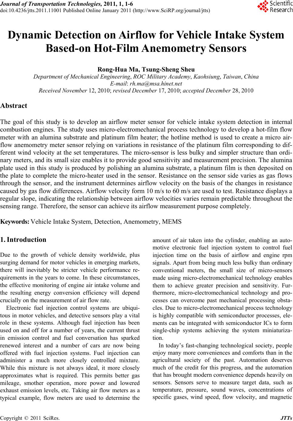 Journal of Transportation Technologies, 2011, 1, 1-6 doi:10.4236/jtts.2011.11001 Published Online January 2011 (http://www.SciRP.org/journal/jtts) Copyright © 2011 SciRes. JTTs Dynamic Detection on Airflow for Vehicle Intake System Based-on Hot-Film Anemometry Sensors Rong-Hua Ma, Tsung-Sheng Sheu Department of Mechanical Engineering, ROC Military Academy, Kaohsiung, Taiwan, China E-mail: rh.ma@msa.hinet.net Received November 12, 2010; revised December 17, 2010; accepted December 28, 2010 Abstract The goal of this study is to develop an airflow meter sensor for vehicle intake system detection in internal combustion engines. The study uses micro-electromechanical process technology to develop a hot-film flow meter with an alumina substrate and platinum film heater; the hotline method is used to create a micro air- flow anemometry meter sensor relying on variations in resistance of the platinum film corresponding to dif- ferent wind velocity at the set temperatures. The micro-sensor is less bulky and simpler structure than ordi- nary meters, and its small size enables it to provide good sensitivity and measurement precision. The alumina plate used in this study is produced by polishing an alumina substrate, a platinum film is then deposited on the plate to complete the micro-heater used in the sensor. Resistance on the sensor side varies as gas flows through the sensor, and the instrument determines airflow velocity on the basis of the changes in resistance caused by gas flow differences. Airflow velocity form 10 m/s to 60 m/s are used to test. Resistance displays a regular slope, indicating the relationship between airflow velocities varies remain predictable throughout the sensing range. Therefore, the sensor can achieve its airflow measurement purpose completely. Keywords: Vehicle Intake System, Detection, Anemometry, MEMS 1. Introduction Due to the growth of vehicle density worldwide, plus surging demand for motor vehicles in emerging markets, there will inevitably be stricter vehicle performance re- quirements in the years to come. In these circumstances, the effective monitoring of engine air intake volume and the resulting energy conversion efficiency will depend crucially on the measurement of air flow rate. Electronic fuel injection control systems are ubiqui- tous in motor vehicles, and detective sensors play a vital role in these systems. Although fuel injection has been used on and off for a number of years, the current thrust in emission control and fuel conversation has sparked renewed interest and a number of cars are now being offered with fuel injection systems. Fuel injection can administer a much more closely controlled mixture. While this mixture is not always ideal, it more closely approximates what is required. This permits better gas mileage, smother operation, more power and lowered exhaust emission levels, etc. Taking air flow meters as a typical example, flow meters are used to determine the amount of air taken into the cylinder, enabling an auto- motive electronic fuel injection system to control fuel injection time on the basis of airflow and engine rpm signals. Apart from being much less bulky than ordinary conventional meters, the small size of micro-sensors made using micro-electromechanical technology enables them to achieve greater precision and sensitivity. Fur- thermore, micro-electromechanical technology and pro- cesses can overcome past mechanical processing obsta- cles. Due to micro-electromechanical process technology is highly compatible with semiconductor processes, ele- ments can be integrated with semiconductor ICs to form single-chip systems achieving the system miniaturiza- tion. In today’s fast-changing technological society, people enjoy many more conveniences and comforts than in the agricultural society of the past. Automation deserves much of the credit for this progress, and the automation that has brought modern convenience depends heavily on sensors. Sensors serve to measure target data, such as temperature, pressure, sound waves, concentrations of specific gases, wind speed, flow velocity, and magnetic  R.-H. MA ET AL. Copyright © 2011 SciRes. JTTs 2 fields, etc. This data must be processed by the conversion of input signals to output signals, amplification, and in- tegration before it can be interpreted by the system so as to respond correctly and appropriately to external physi- cal phenomena. As a consequence, the ability of sensors to quickly obtain correct data plays a key role in automa- tion, control, and actuation. This is how the need for air stream and airflow direction sensors arose. Airflow rate and direction sensing are important in many fields, including the monitoring on vehicle engine performance. In past literature on the subject, flow me- ters were usually classified as thermal and non-thermal sensors on the basis of their sensing method. Among non-thermal gas flow sensors, designs integrating a pie- zoresistive structure with a cantilever arm are attracting favorable attention due to their high sensitivity, high sta- bility, and good linearity. 1.1. Micro-Electromechanical Systems The physicist Richard P. Feyman first proposed shrink- ing science and engineering to a microscopic scale at a physics conference in 1959, and suggested that this would be a technological milestone for the future. The invention of the integrated circuit spurred the rapid ex- pansion and development of the electronic element in- dustry. More than forty years later, the electronics indus- try is developing process technologies capable of achie- ving even tinier dimensions [1-3]. Apart from enabling many technical improvements, this miniaturization trend has also made electronic elements increasingly inexpen- sive. Micro-electromechanical system (MEMS) technol- ogy is a derivation of semiconductor process technology, and therefore draws on the advantages of semiconductor manufacturing technology [4,5]. MEMS technologies are used in an extremely wide range of interdisciplinary ap- plications spanning the areas of physics, chemistry, elec- tronics, machinery, optics, and materials science, etc. MEMS also represents an improvement on conventional mechanical processing technologies, and offers the ad- vantages of small dimensions, high accuracy, large-scale batch production, and low costs. Furthermore, MEMS technology allows the integration of micro-sensors with other circuits or sensors in order to achieve more power- ful functions and greater stability and reliability [6,7]. Adamec et al. [8] fabricated a multi-axis hotwire ane- mometer with four thermo resistor to evaluate flow di- rection with a power consumption of 25mW. Makinwa et al. [9] presented a circular-type thermal flow sensor consists of a heater to detect flow direction and velocity. Recently, non-thermal gas flow meters have been devel- oped. These devices have the advantages of lower power consumption and an improved potential for integration with other sensors. In spite the previous studies investi- gated many thermal and non-thermal types of flow sen- sors, those based on hot-films have not been well dis- cussed. 2. Design The flow sensors of the study are fabricated on alumina and utilize platinum resistors as heating and sensing de- vices. The sensors tested with different micro-heater and sensing mechanism orientations, and investigated the sensing characteristics of single-chip and double-chip sensors of different sizes. The micro-gas sensors investi- gated in this study employed an alumina substrate on which platinum was deposited to produce a micro-heater and sensing mechanism (Figure 2). Because micro-heaters can continuously produce a controllable, constant tem- perature environment, providing a stabile power system to the micro-heater can maintain the sensor's operating temperature at the desired level. Wind tunnel experi- ments were used in conjunction with a connected sensor to observe the amount of temperature varies. 2.1. Hotline Airflow Anemometry Meter Design Principles Hot-line type anemometry meters include several com- monly-seen structures: heater, heat sensor, and tempera- ture compensation resistor. Hotline meters employ three chief sensing principles: constant current, constant tem- perature, and constant power. 1) When there is a constant current, temperature dif- ferences caused by the fluid generate different signals. 2) When there is a constant heater temperature, dif- ferences in output power can be used to determine the flow rate. 3) When there is constant power, information con- cerning the fluid can be determined from the effect of the fluid on resistance and current. The hotline wind speed meter proposed in this study uses a platinum heating resistor that generates heat when a current is flowing. Forced convection will remove the heat, changing the resistance of the heat sensor. In a normal environment, the problem of heat dissipation must be overcome. In Figure 3, the sum of natural con- vection QN, heat conduction QC, thermal radiation QR, and forced convection QF is the total heat output of the heater (see Equation (1)). A temperature compensation mechanism can be used to deal with the problems of natural convection and thermal radiation and maintain a balance with the environmental temperature. PQNQFQCQR (1) 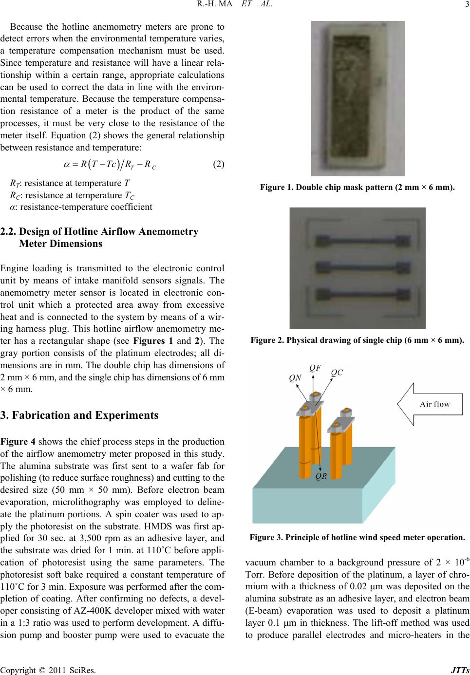 R.-H. MA ET AL. Copyright © 2011 SciRes. JTTs 3 Because the hotline anemometry meters are prone to detect errors when the environmental temperature varies, a temperature compensation mechanism must be used. Since temperature and resistance will have a linear rela- tionship within a certain range, appropriate calculations can be used to correct the data in line with the environ- mental temperature. Because the temperature compensa- tion resistance of a meter is the product of the same processes, it must be very close to the resistance of the meter itself. Equation (2) shows the general relationship between resistance and temperature: TC RT Tc RR (2) RT: resistance at temperature T RC: resistance at temperature TC α: resistance-temperature coefficient 2.2. Design of Hotline Airflow Anemometry Meter Dimensions Engine loading is transmitted to the electronic control unit by means of intake manifold sensors signals. The anemometry meter sensor is located in electronic con- trol unit which a protected area away from excessive heat and is connected to the system by means of a wir- ing harness plug. This hotline airflow anemometry me- ter has a rectangular shape (see Figures 1 and 2). The gray portion consists of the platinum electrodes; all di- mensions are in mm. The double chip has dimensions of 2 mm × 6 mm, and the single chip has dimensions of 6 mm × 6 mm. 3. Fabrication and Experiments Figure 4 shows the chief process steps in the production of the airflow anemometry meter proposed in this study. The alumina substrate was first sent to a wafer fab for polishing (to reduce surface roughness) and cutting to the desired size (50 mm × 50 mm). Before electron beam evaporation, microlithography was employed to deline- ate the platinum portions. A spin coater was used to ap- ply the photoresist on the substrate. HMDS was first ap- plied for 30 sec. at 3,500 rpm as an adhesive layer, and the substrate was dried for 1 min. at 110˚C before appli- cation of photoresist using the same parameters. The photoresist soft bake required a constant temperature of 110˚C for 3 min. Exposure was performed after the com- pletion of coating. After confirming no defects, a devel- oper consisting of AZ-400K developer mixed with water in a 1:3 ratio was used to perform development. A diffu- sion pump and booster pump were used to evacuate the Figure 1. Double chip mask pattern (2 mm × 6 mm). Figure 2. Physical drawing of single chip (6 mm × 6 mm). Figure 3. Principle of hotline wind speed meter operation. vacuum chamber to a background pressure of 2 × 10⁻⁶ Torr. Before deposition of the platinum, a layer of chro- mium with a thickness of 0.02 μm was deposited on the alumina substrate as an adhesive layer, and electron beam (E-beam) evaporation was used to deposit a platinum layer 0.1 μm in thickness. The lift-off method was used to produce parallel electrodes and micro-heaters in the 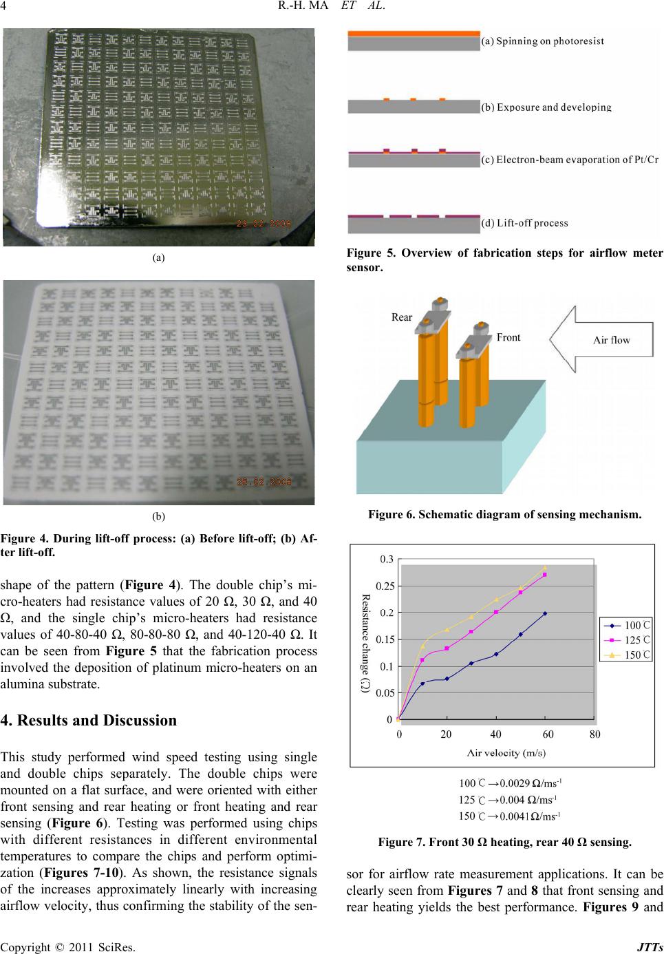 R.-H. MA ET AL. Copyright © 2011 SciRes. JTTs 4 (a) (b) Figure 4. During lift-off process: (a) Before lift-off; (b) Af- ter lift-off. shape of the pattern (Figure 4). The double chip’s mi- cro-heaters had resistance values of 20 Ω, 30 Ω, and 40 Ω, and the single chip’s micro-heaters had resistance values of 40-80-40 Ω, 80-80-80 Ω, and 40-120-40 Ω. It can be seen from Figure 5 that the fabrication process involved the deposition of platinum micro-heaters on an alumina substrate. 4. Results and Discussion This study performed wind speed testing using single and double chips separately. The double chips were mounted on a flat surface, and were oriented with either front sensing and rear heating or front heating and rear sensing (Figure 6). Testing was performed using chips with different resistances in different environmental temperatures to compare the chips and perform optimi- zation (Figures 7-10). As shown, the resistance signals of the increases approximately linearly with increasing airflow velocity, thus confirming the stability of the sen- Figure 5. Overview of fabrication steps for airflow meter sensor. Figure 6. Schematic diagram of sensing mechanism. Figure 7. Front 30 Ω heating, rear 40 Ω sensing. sor for airflow rate measurement applications. It can be clearly seen from Figures 7 and 8 that front sensing and rear heating yields the best performance. Figures 9 and 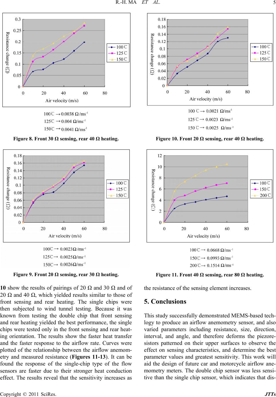 R.-H. MA ET AL. Copyright © 2011 SciRes. JTTs 5 Figure 8. Front 30 Ω sensing, rear 40 Ω heating. Figure 9. Front 20 Ω sensing, rear 30 Ω heating. 10 show the results of pairings of 20 Ω and 30 Ω and of 20 Ω and 40 Ω, which yielded results similar to those of front sensing and rear heating. The single chips were then subjected to wind tunnel testing. Because it was known from testing the double chip that front sensing and rear heating yielded the best performance, the single chips were tested only in the front sensing and rear heat- ing orientation. The results show the faster heat transfer and the faster response to the airflow rate. Curves were plotted of the relationship between the airflow anemom- etry and measured resistance (Figures 11-13). It can be found the response of the single-chip type of the flow sensors are faster due to their stronger heat conduction effect. The results reveal that the sensitivity increases as Figure 10. Front 20 Ω sensing, rear 40 Ω heating. Figure 11. Front 40 Ω sensing, rear 80 Ω heating. the resistance of the sensing element increases. 5. Conclusions This study successfully demonstrated MEMS-based tech- logy to produce an airflow anemometry sensor, and also varied parameters including resistance, size, direction, interval, and angle, and therefore deforms the piezore- sistors patterned on their upper surfaces to observe the effect on sensing characteristics, and determine the best parameter values and greatest sensitivity. This work will aid the design of future car and motorcycle airflow ane- mometry meters. The double chip sensor was less sensi- tive than the single chip sensor, which indicates that dis- 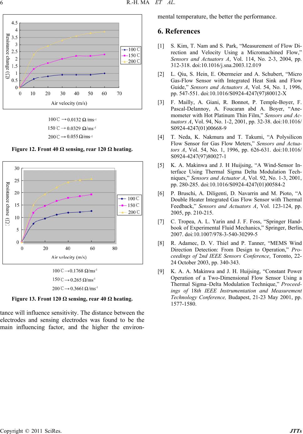 R.-H. MA ET AL. Copyright © 2011 SciRes. JTTs 6 Figure 12. Front 40 Ω sensing, rear 120 Ω heating. Figure 13. Front 120 Ω sensing, rear 40 Ω heating. tance will influence sensitivity. The distance between the electrodes and sensing electrodes was found to be the main influencing factor, and the higher the environ- mental temperature, the better the performance. 6. References [1] S. Kim, T. Nam and S. Park, “Measurement of Flow Di- rection and Velocity Using a Micromachined Flow,” Sensors and Actuators A, Vol. 114, No. 2-3, 2004, pp. 312-318. doi:10.1016/j.sna.2003.12.019 [2] L. Qiu, S. Hein, E. Obermeier and A. Schubert, “Micro Gas-Flow Sensor with Integrated Heat Sink and Flow Guide,” Sensors and Actuators A, Vol. 54, No. 1, 1996, pp. 547-551. doi:10.1016/S0924-4247(97)80012-X [3] F. Mailly, A. Giani, R. Bonnot, P. Temple-Boyer, F. Pascal-Delannoy, A. Foucaran abd A. Boyer, “Ane- mometer with Hot Platinum Thin Film,” Sensors and Ac- tuators A, Vol. 94, No. 1-2, 2001, pp. 32-38. doi:10.1016/ S0924-4247(01)00668-9 [4] T. Neda, K. Nakmura and T. Takumi, “A Polysilicon Flow Sensor for Gas Flow Meters,” Sensors and Actua- tors A, Vol. 54, No. 1, 1996, pp. 626-631. doi:10.1016/ S0924-4247(97)80027-1 [5] K. A. Makinwa and J. H Huijsing, “A Wind-Sensor In- terface Using Thermal Sigma Delta Modulation Tech- niques,” Sensors and Actuator A, Vol. 92, No. 1-3, 2001, pp. 280-285. doi:10.1016/S0924-4247(01)00584-2 [6] P. Bruschi, A. Diligenti, D. Navarrin and M. Pioto, “A Double Heater Integrated Gas Flow Sensor with Thermal Feedback,” Sensors and Actuators A, Vol. 123-124, pp. 2005, pp. 210-215. [7] C. Tropea, A. L. Yarin and J. F. Foss, “Springer Hand- book of Experimental Fluid Mechanics,” Springer, Berlin, 2007. doi:10.1007/978-3-540-30299-5 [8] R. Adamec, D. V. Thiel and P. Tanner, “MEMS Wind Direction Detection: From Design to Operation,” Pro- ceedings of 2nd IEEE Sensors Conference, Toronto, 22- 24 October 2003, pp. 340-343. [9] K. A. A. Makinwa and J. H. Huijsing, “Constant Power Operation of a Two-Dimensional Flow Sensor Using a Thermal Sigma–Delta Modulation Technique,” Proceed- ings of 18th IEEE Instrumentation and Measurement Technology Conference, Budapest, 21-23 May 2001, pp. 1577-1580. |