Engineering, 2013, 5, 416-419
http://dx.doi.org/10.4236/eng.2013.510B085 Published Online October 2013 (http://www.scirp.org/journal/eng)
Copyright © 2013 SciRes. ENG
A Uniaxial Loading Device for Studying Mechanor esponses
of Single Plant Cell*
Liqing Zhu1,2, Xue Fu3,4, Jie Yan5, Junyu Liu5
1School of Chemistry and Chemical Engineering, Chongqing University of Science and Technology, Chongqing, China;
2College of Bioengineering Chongqing University, Chongqing, China
3School of Chemistry and Chemical Engineering, Southwest Petroleum University, Chengdu, China
4Key Laboratory of Biorheological Science and Technology (Chongqing University), Ministry of Education, Chongqing, China
5College of Bioengineering Chongqing University, Chongqing, China
Email: c qz huliqing@126.com, fuxue1981@163.com, yanjie185@sina.com, Biotljy@163.com
Received 2013
ABSTRACT
A system which consists of a loading chamber unit, displacement sensor, data collector and processor, and a feedback
control, was established for applying mechanical forces to single plant cells. The method works by compressing an agar
cell-suspension block between parallel surfaces through using a force-feedback control circuit coupled to a microchip,
delivering the pre-defined. The actual controlled stimulus is achieved whilst measuring the force being imposed on the
cell, and its deformation. The Arabidopsis protoplasts were utilized to test the system. It provides an experimental ap-
proach to investigate the mechanoresponses of plant cells in vitro conditions.
Keywords: Mechanical Loading; Plant Cell; Chamber; Feedback Control
1. Introduction
Plants are unable to escape from an unfavorable envi-
ronment, they must respond to both endogenous and ex-
ogenous stimulus starting with a transduction of mecha-
nical perturbation into a biological signal and ending into
a global response as modification of growth, which is
known as thigmomorphogenesis [1]. Besides, plants use
regulated cell expansion to adapt their form to environ-
mental conditions. In contrast with most non-living ma-
terial systems, the cell structure is a dyn amic system that
adapts to its local mechanochemical environment, the
mechanical behavior of a living plant cell can’t be cha-
racterized only in terms of mechanical properties [2].
Observation of the patterns of cell expansion and wall
orientation is challenging because it occurs on several
scales, which range from the cellular to the tissue level,
and ultimately to a consideration of the whole plant. In
particular, application of ex ternal mechanical stimuli can
induce biochemical reactions, including the synthesis of
new biomolecules and the enhanced interaction among
biomolecules that can generate mechanical forces [3].
Despite the experimental sophistication and computa-
tional approaches in cell and molecular biology, the me-
chanisms by which mechanical stimuli could influence
cell signaling processes are poorly understood [4,5]. In
the past few decades, engineering fundamentals have been
used to design devices for probing the mechanical prop-
erties of living cells [6,7]. Here our focus is on the de-
velopment of mechanical stimulating system, which pro-
vided organismal survival conditions and measurable forces
delivery. In the present work, the authors report the use
of compressive force generated by a controllable loading
system as a tool to investigate cell in situ with the actual
stress and alteration of living cells’ geometry [8]. Our de -
sign of this system will allow us to conduct real-time stu-
dies for cellular responses to compress forces on samples.
Specifically, we want to satisfy the following criteria:
1) The system has to be small enough to be allowed
conventional and fluorescence microscopic observation
at high res olution .
2) The system should be a sustainable plant cell cul-
ture platform which can support the regeneration of a
small portion of cells in a long term culture.
3) The precision of linearity of displac ement sensor for
the system has to be accurate enough to be achieved to
conduct accurate compress stress analysis with an upper
limit of 300 mN.
2. Equipment and Method Development
1) System Design
The basic loading technique was that described by
*Supported by the Science and Technology Project of Chongqing Mu-
nicipal Education Commission, China (Project No. KJ121403).
L. Q. ZHU ET AL.
Copyright © 2013 SciRes. ENG
417
Lintilhac et al. [9]. An in-vitro experimental systems are
capable of generating controlled and well-defined me-
chanical forces were developed, which as a typical of
micro loading and measuring system, the basic compo-
nents of this apparatus are: loading unit, displacement or
deformation sensor, data collector and processor, and
feedback control. The conceptual simple schematic of
structure of the system is shown in Figure 1.
2) Device Fabrication
The chamber of the apparatus was constructed consist-
ing of one 2.0 mm thick deck of cast acrylic (30.0 mm ×
90.0 mm).
The deck has one threaded holes, in which a connect-
ing rod was set for connected to the stepper motor. To
enable accurate, sustainable application of forces, a step-
per motor (57BYG250A, stepper angular distance: 0.9˚/
1.8˚, operating voltage: 4.5 - 7.5 V) that mounted to the
top of pedestal was utilized to automate the movement of
applying connecting rod, which served as the source to
the deformation of test specimens. The stepper motor has
a threaded rotor which engages a threaded lead screw,
and the lead screw in turn is attached to a guide rod
which could slide freely along the axis of the guide way
(to maintain alignment of the slide relative to the medium
planar plate). The guide way enable positioning planar
motion of the subsequently connected applying rod, ap-
plying baffle (20.0 mm × 15.0 mm) that can be gradually
and accurately energized to move toward and away from
the vertical slide of the sample in order to provide a di-
rect forces (ranged from 50 to 300 mN) to the test spe ci-
mens disposed in the chamber. A schematic diagram of
the apparatus is shown in Figure 2.
3) Feedback control technique
In general, for recording the force-displacement data
during the application of stress, sensor to simultaneously
monitor load and displacement is required, respectively.
Automatic strain measurement described in the work was
adopted with half-bridge circuit, which is composed of
some strain sensitive electrical resistance strain gauges.
The strain gauges (sensitivity factor: 2.12% ± 1%) them-
selves were placed on the surface of a piece of leaf spring,
whose one end was anchored on the guide rod and an-
other bolted to a certain position of the applying rod,
amplifying and transforming the displacement signal to
strain gauges. It is easy to find the relationship between
the e maximal actuator strain εmax and the force F, which
applied on the free end of leaf spring:
max 2
6Fl
Ebh
ε
=
(1)
Where E is its elastic modulus, l, b and h are its length,
width and height of the rectangular se ction of leaf spring ,
respectively. When the external forces are applied, the
maximal strain will be produced close to the root of leaf
spring. Equation (1) can be used to obtain the consequen-
tial strain agar.
The altered resistance signals were collected and re-
gulated by the strain indicator (BZ2201, Beidai River
Land Science and Technology Ltd.), and then transferred
to the control and monitoring subsystem, thereby the dis-
placement could be recognized directly from the test spe-
cimens into a data acquisition system. Specifically, the
single channel dynamic strain indicator is a versatile,
Samples
Micro-probe
Stepper
motor
Strain
gauges
Strain
inductor
Stepper motor
drive circuit
Micro controller unit
Display Input
Figure 1. Block diagram of simple structure of the system.
Figure 2. Schematic diagram of the apparatus.
Vertical Base Plate
Guide Rod
Chamber
Microscope
Sample
Applying Baffle
Leaf Spring
Strain Gauge
Horizontal Transparent Base Plate
Stepper MotorLead Screw
L. Q. ZHU ET AL.
Copyright © 2013 SciRes. ENG
418
high-precision laboratory-type instrument developed for
use with strains gauges and strain gauge-based transduc-
ers to correcting for the spread in gauge resistance and
gauge factor. For overcoming the circumstances and to
compensate the thermal effect, temperature compensa-
tion circuit was designed mainly by means of two exter-
nal temperature compensating gauges.
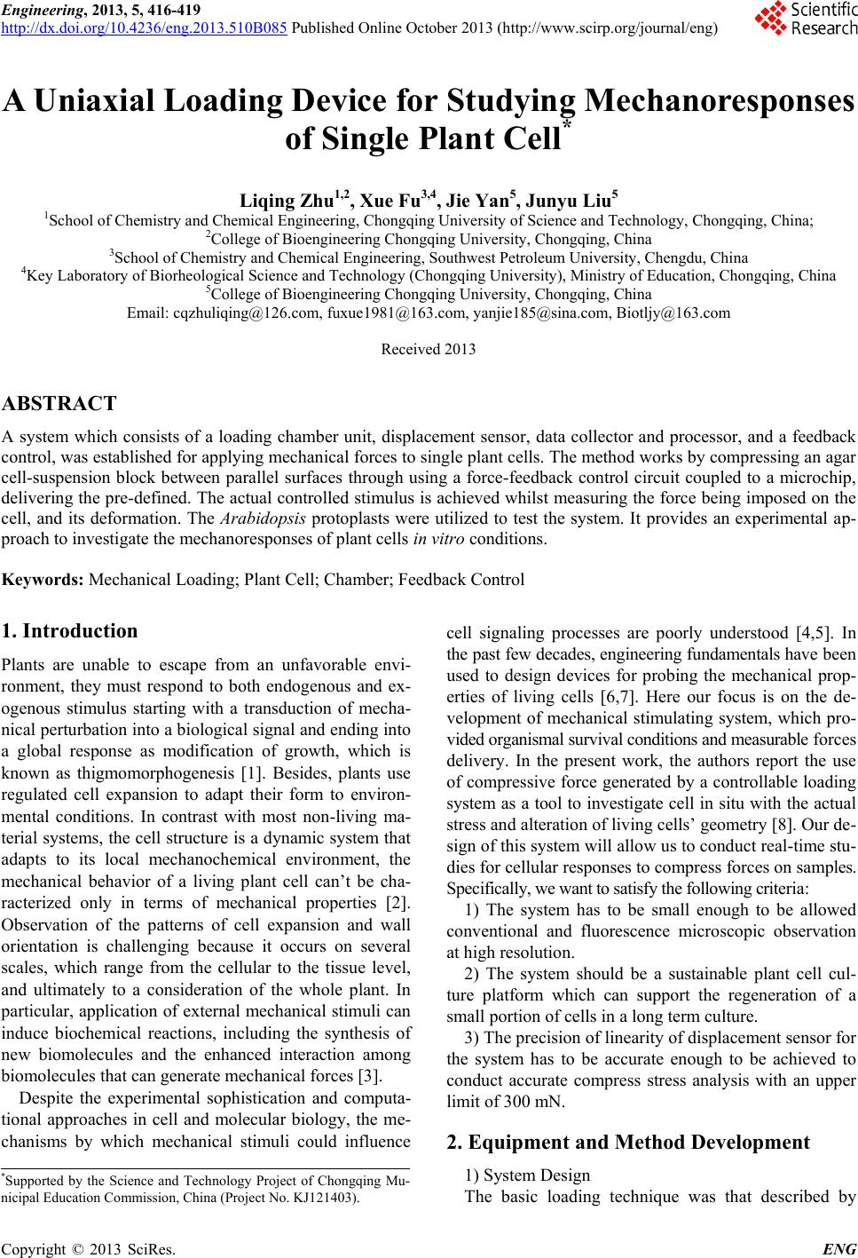
The micro-controller unit (MCU) based closed-loop
control subsystem was built to measure and manipulate
this device. The data acquisition and control unit consists
of a multifunction single chip (SPCE061A, Sunplus Tech-
nology Company Limited) [10], which provides seven
channel 10-bit high-speed analog-to-digital converters
(ADC), and two 10-bit digital-to-analog con ve rt e r (D AC)
output channels, combined with higher processing speed
(up to 49.152 MHz) . The voltage r egulator SPY0029 was
utilized as power source to provide 3.3 V d.c. based on
the operating voltage of single chip that ranged from 2.6
to 3.6 V. The input signal comes from a microchip pro-
gram based on the DAC, it could predefine the desired
force level. In addition, the I/O channel provides output
electronically control as well as impulse wave signal. A
four phase stepper motor component is driven to deliver
and maintain a desired precise force with the uniaxial
movement. This feedback control circuit provides a real-
time visual indication on the digital display of the strain
indicator output, the signal of the strain gauge and the
contr ol si gnal woul d be compa red whil e the for ce is sensed.
3. System Test
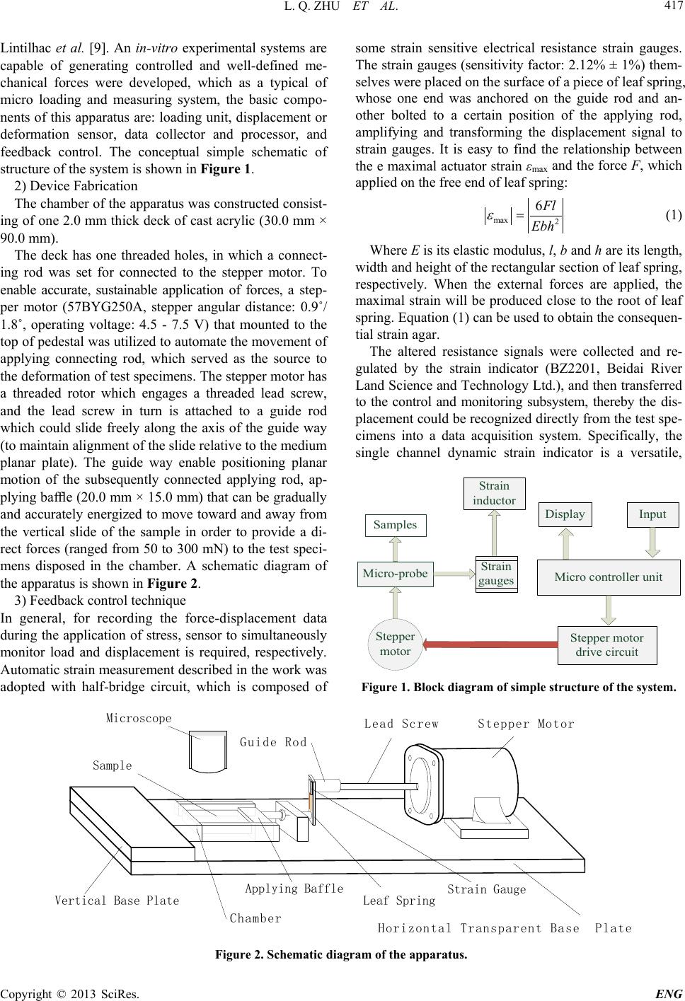
The loading system must be calibrated by verifying the
accuracy and precision of linearity of the displacement
sensor. To verify this device, the protoplasts isolated from
the wild-type Arabidopsis thaliana (ecotype Columbia
Col-0) rosette leaves were retained as experimental ma-
terial, Protoplasts were then immobilized by gently swirl-
ing them into low-melting-point agar in MS medium sup-
plemented with 0.4 moll1 mannitol, 0.1% MES, sucrose,
2,4-dichlorophenoxyacetic acid, and self-conditioned me-
dium harvested from suspension cultured Arabidopsis
cells [11]. Then the loaded test specimen which embed-
ded with living cells was removed and chipped into slices
of approximately 2.0 - 5.0 mm thick, and it was placed
onto the chamber of the mechanical loading apparatus
described above.
Hamant has reported that microtubule orientation in
the shoot apical meristem was found to follow the orien-
tation of stress patterns in the organ [12], this conclusion
supports the prior viewpoint that th e lo c al microinduction
of expansin expression and resulting cell wall softening
is sufficient to induce morphogenetic processes, leading
to the initiation of leaf structures from the shoot apical
meristem [13]. Continuous uniaxial compressive force (at
approximately 50 - 300 mN) was imposed on the oppo-
site sides of agar block, time ranged from 60 seconds to
1200 seconds, this allowed a microscope to be brought
close to the cell under test. Our device could play a role
in the relative research field. The applying baffle dis-
placement and the cell deformation could be observed,
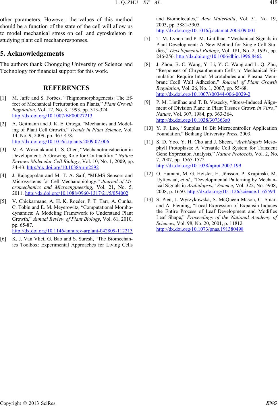
and a force-deformation curve generated. As shown in
Figure 3, the deformation of embedded protoplasts under
constant mechanical strain is visible in the substrate, the
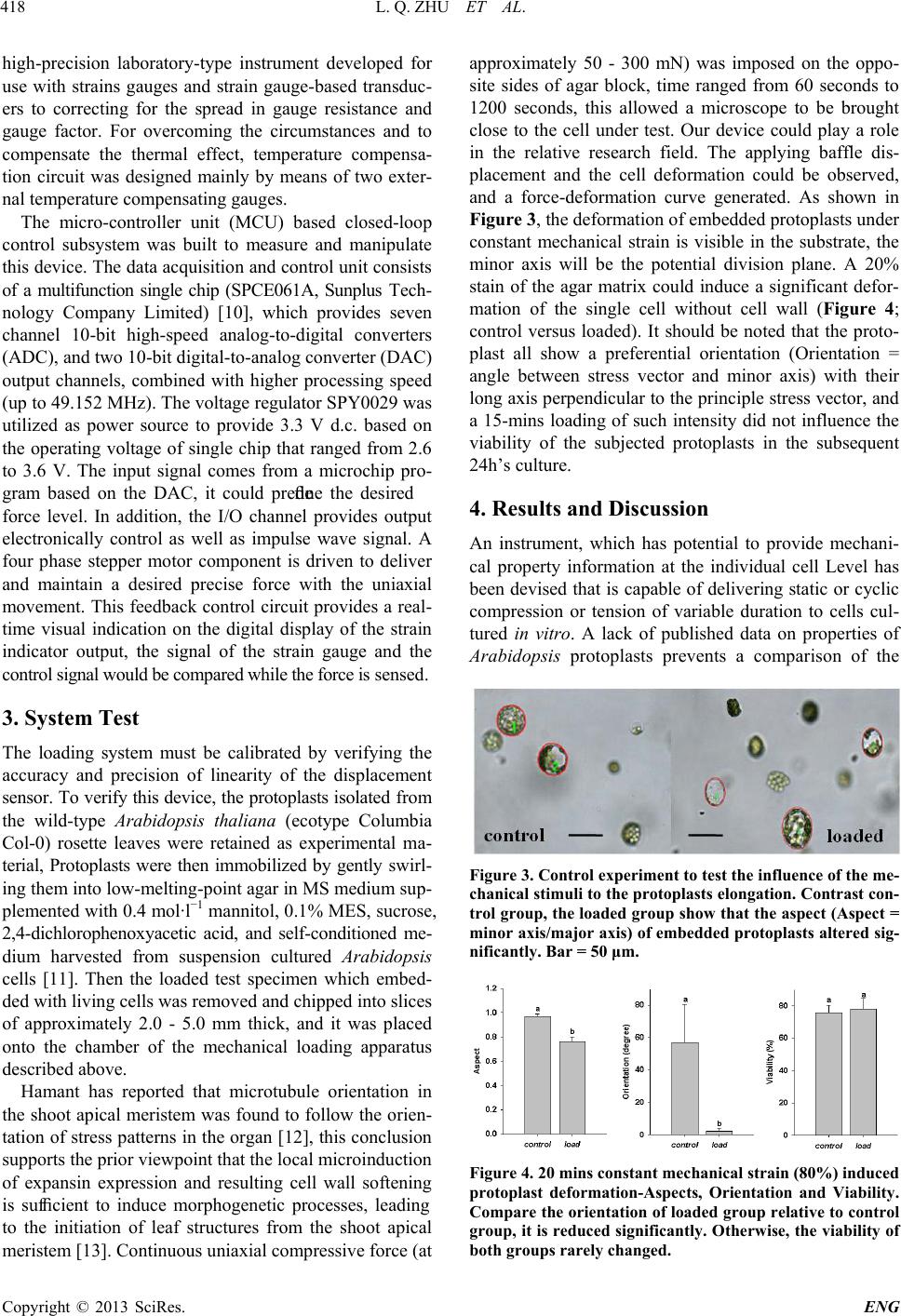
minor axis will be the potential division plane. A 20%
stain of the agar matrix could induce a significant defor-
mation of the single cell without cell wall (Figure 4;
control versus loaded). It should be noted that the proto-
plast all show a preferential orientation (Orientation =
angle between stress vector and minor axis) with their
long axis perpendicular to the principle stress vector, and
a 15-mins loading of such intensity did not influence the
viability of the subjected protoplasts in the subsequent
24h’s culture.
4. Results and Discussion
An instrument, which has potential to provide mechani-
cal property information at the individual cell Level has
been devised that is capable of delivering static or cyclic
compression or tension of variable duration to cells cul-
tured in vitro. A lack of published data on properties of
Arabidopsis protoplasts prevents a comparison of the
Figure 3. Control experiment to test the influence of t he me -
chanical stimuli to the protoplasts elongation. Contrast con-
trol group, the loaded group show that the aspect (Aspect =
minor axis/major axis) of embedded protoplasts altered sig-
nificantly. Bar = 50 μm.
Figure 4. 20 mins constant mechanical strain (80%) induced
protoplast deformation-Aspects, Orientation and Viability.
Compare the orientation of loaded group relative to control
group, it is reduc ed significantly. Ot herwise, the viability of
both groups rarely changed.
L. Q. ZHU ET AL.
Copyright © 2013 SciRes. ENG
419
other parameters. However, the values of this method
should be a function of the state of the cell will allow us
to model mechanical stress on cell and cytoskeleton in
studyin g plant cell mechanorespons e s.
5. Acknowledgements
The authors thank Chongqing University of Science and
Technology for financial support for this work.
REFERENCES
[1] M. Jaffe and S. Forbes, “Thigmomorphogenesis: The Ef-
fect of Mechanical Perturbation on Plants,” Plant Growth
Regulation, Vol. 12, No. 3, 1993, pp. 313-324.
http://dx.doi.org/10.1007/BF00027213
[2] A. Geitmann and J. K. E. Ortega, Mechanics and Model-
ing of Plant Cell Growth,” Trends in Plant Science, Vol.
14, No. 9, 2009, pp. 467-478.
http://dx.doi.org/10.1016/j.tplants.2009.07.006
[3] M. A. Wozniak and C. S. Chen, Mechanotransduction in
Development: A Growing Role for Contractility,” Nature
Reviews Molecular Cell Biology, Vol. 10, No. 1, 2009, pp.
34-43. http://dx.doi.org/10.1038/nrm2592
[4] J. Rajagopalan and M. T. A. Saif, “MEMS Sensors and
Microsystems for Cell Mechanobiology,” Journal of Mi-
cromechanics and Microengineering, Vol. 21, No. 5,
2011. http://dx.doi.org/10.1088/0960-1317/21/5/054002
[5] V. Chickarmane, A. H. K. Roeder, P. T. Tarr, A. Cunha,
C. Tobin and E. M. Meyerowitz, Computational Morpho-
dynamics: A Modeling Framework to Understand Plant
Growth,” Annual Review of Plant Biology, Vol. 61, 2010,
pp. 65-87.
http://dx.doi.org/10.1146/annurev-arplant-042809-112213
[6] K. J. Van Vliet, G. Bao and S. Suresh, The Biomechan-
ics Toolbox: Experimental Approaches for Living Cells
and Biomolecules,” Acta Materialia, Vol. 51, No. 19,
2003, pp. 5881-5905.
http://dx.doi.org/10.1016/j.actamat.2003.09.001
[7] T. M. Lynch and P. M. Lintilhac, Mechanical Signals in
Plant Development: A New Method for Single Cell Stu-
dies,” Developmental Biology, Vol. 181, No. 2, 1997, pp.
246-256. http://dx.doi.org/10.1006/dbio.1996.8462
[8] J. Zhou, B. C. Wang, Y. Li, Y. C. Wang and L. Q. Zhu,
Responses of Chrysanthemum Cells to Mechanical Sti-
mulation Require Intact Microtubules and Plasma Mem-
brane¨Ccell Wall Adhesion,” Journal of Plant Growth
Regulation, Vol. 26, No. 1, 2007, pp. 55-68.
http://dx.doi.org/10.1007/s00344-006-0029-2
[9] P. M. Lintilhac and T. B. Vesecky, Stress-Induced Ali gn-
ment of Division Plane in Plant T issues Grown in Vitro,”
Nature, Vol. 307, 1984, pp. 363-364.
http://dx.doi.org/10.1038/307363a0
[10] Y. F. Luo, Sunplus 16 Bit Microcontroller Application
Foundation,” Beihang University Press, 2003.
[11] S. D. Yoo, Y. H. Cho and J. Sheen, Arabidopsis Meso-
phyll Protoplasts: A Versatile Cell System for Transient
Gene Expression Analysis,” Nature Protocols, Vol. 2, No.
7, 2007, pp. 1565-1572.
http://dx.doi.org/10.1038/nprot.2007.199
[12] O. Hamant, M. G. Heisler, H. Jönsson, P. Krupinski, M.
Uyttewaal, et al., “Developmental Patterning by Mechan-
ical Signals in Arabidopsis,” Science, Vol. 322, No. 5908,
2008, p. 1650. http://dx.doi.org/10.1126/science.1165594
[13] S. Pien, J. Wyrzykowska, S. McQueen-Mason, C. Smart
and A. Fleming, Local Expression of Expansin Induces
the Entire Process of Leaf Development and Modifies
Leaf Shape,” Proceedings of the National Academy of
Sciences, Vol. 98, No. 20, 2001, p. 11812.
http://dx.doi.org/10.1073/pnas.191380498