Paper Menu >>
Journal Menu >>
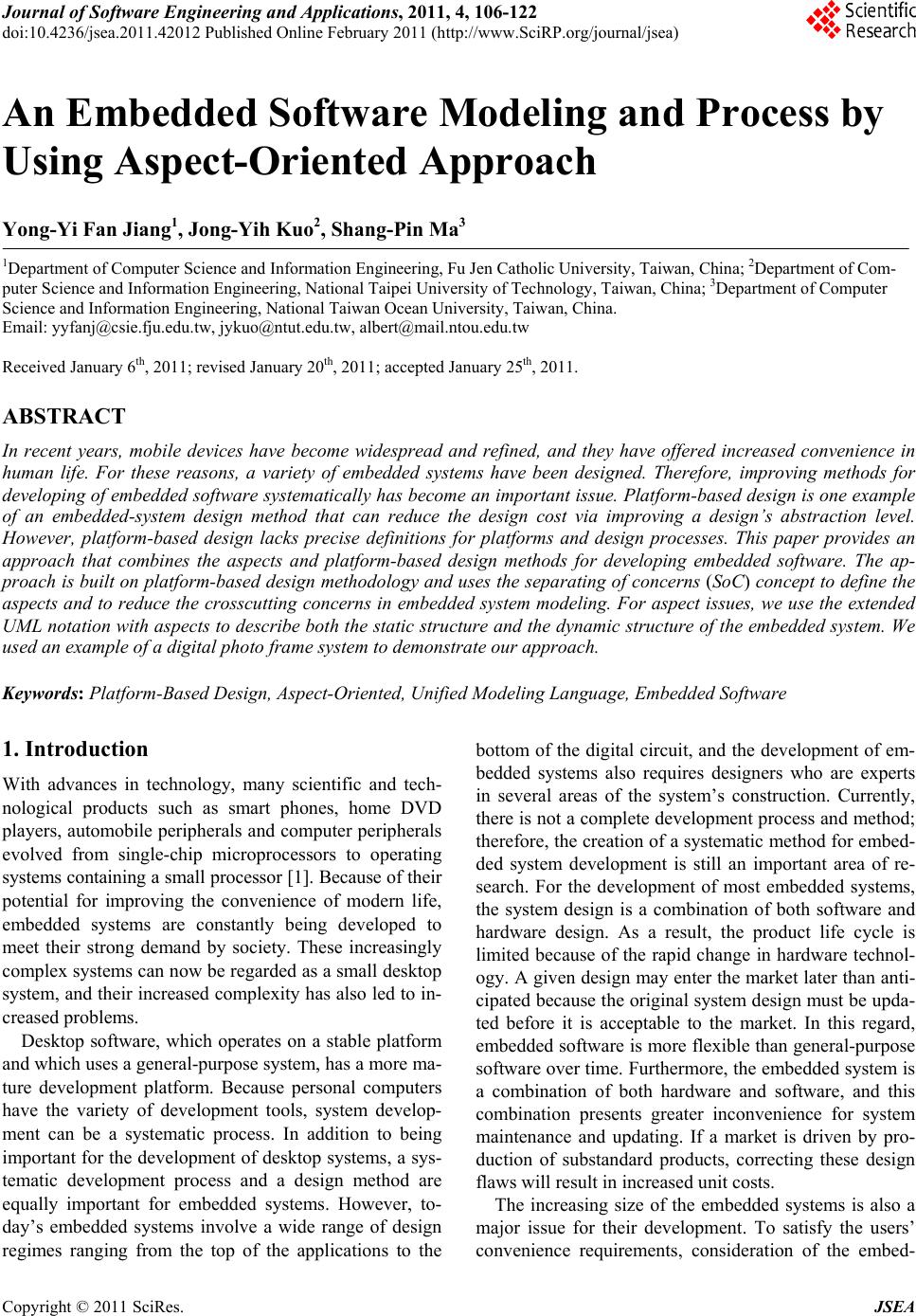 Journal of Software Engineering and Applications, 2011, 4, 106-122 doi:10.4236/jsea.2011.42012 Published Online February 2011 (http://www.SciRP.org/journal/jsea) Copyright © 2011 SciRes. JSEA An Embedded Software Modeling and Process by Using Aspect-Oriented Approach Yong-Yi Fan Jiang1, Jong -Y ih Kuo2, Shang-Pin Ma3 1Department of Compu t e r Science and Information Engineering, Fu Jen Catholic University, Taiwan, China; 2Department of Com- puter Science and Information Engineering, National Taipei University of Technology, Taiwan, China; 3Department of Computer Science and Information Engineering, National Taiwan Ocean University, Taiwan, China. Email: yyfanj@csi e . fju.edu.tw, jykuo@ntut.edu.tw, albert@mail.ntou.edu.tw Received January 6th, 2011; revised January 20th, 2011; accepted January 25th, 2011. ABSTRACT In recent years, mobile devices have become widespread and refined, and they have offered increased convenience in human life. For these reasons, a variety of embedded systems have been designed. Therefore, improving methods for developing of embedded software systematically has become an important issue. Platform-based design is one example of an embedded-system design method that can reduce the design cost via improving a design’s abstraction level. However, platform-based design lacks precise definitions for platforms and design processes. This paper provides an approach that combines the aspects and platform-based design methods for developing embedded software. The ap- proach is bu ilt on platform-based design meth odology and uses the separating of concerns (SoC) concept to define the aspects and to reduce the crosscutting concerns in embedded system modeling. For aspect issues, we use the extended UML notation with aspects to describe both the static structure and the dynamic structure of the embedded system. We used an example of a digital photo frame system to demonstrate our approach. Keywords: Platform-Based Design, Aspect-Oriented, Unified Modeling Language, Embedded Software 1. Introduction With advances in technology, many scientific and tech- nological products such as smart phones, home DVD players, automobile peripherals and computer peripherals evolved from single-chip microprocessors to operating systems containing a small processor [1]. Because of their potential for improving the convenience of modern life, embedded systems are constantly being developed to meet their strong demand by society. These increasingly complex systems can now be regarded as a small desktop system, and their increased complexity has also led to in- creased problems. Desktop software, which operates on a stable platform and which uses a general-purpose system, has a more ma- ture development platform. Because personal computers have the variety of development tools, system develop- ment can be a systematic process. In addition to being important for the development of desktop systems, a sys- tematic development process and a design method are equally important for embedded systems. However, to- day’s embedded systems involve a wide range of design regimes ranging from the top of the applications to the bottom of the digital circuit, and the development of em- bedded systems also requires designers who are experts in several areas of the system’s construction. Currently, there is not a complete develo pment process and method; therefore, the creation of a systematic method for embed- ded system development is still an important area of re- search. For the development of most embedded systems, the system design is a combination of both software and hardware design. As a result, the product life cycle is limited because of the rapid change in hardware technol- ogy. A given design may enter the market later than anti- cipated because the original system design must be upda- ted before it is acceptable to the market. In this regard, embedded software is more flexible than general-purpose software over time. Furthermore, the embedded system is a combination of both hardware and software, and this combination presents greater inconvenience for system maintenance and updating. If a market is driven by pro- duction of substandard products, correcting these design flaws will result in increased unit costs. The increasing size of the embedded systems is also a major issue for their development. To satisfy the users’ convenience requirements, consideration of the embed-  An Embedded Software Modeling and Process by Using Aspect-Oriented Approach Copyright © 2011 SciRes. JSEA 107 ded system’s size is an increasingly important considera- tion. Although the trend in embedd ed system design is to provide greater resource capacity, the system’s calcula- tion performance is still not that of a general desk top sys- tem. Users also cannot replace the embedded system’s components. Furthermore, upgrading the hardware’s cal- culation capability means greater power consumption, which is an important issue for embedded systems. One of the resolutions for this issue is to reduce the software burden on the hardware. In terms of PC hardware deployment, Vincentelli [2] proposed a platform-based design approach that has been used in the industrial domain and has a certain degree of effectiveness. Platform-based design improves the system level of the design abstraction. Through a clear definition of the platforms, mapping of the API platform to the ar- chitecture platform allowed for completion of the design. The abstract levels of system development reduced errors and improved the design’s reusability. It also redu ced the time-to-market for embedded systems and reduced design costs. In recent years, considerations of the embedded sys- tem’s security needs and its non-functional requirements have become the focus of aspect-oriented design. Aspect- oriented design involves the separation-of-concerns based method [3], which is used to improve the size of inter- connected software systems. It uses a modular approach to solve the problems presented by crosscutting concerns that arise in object-oriented software development. This paper focuses on the combination of aspect-ori- ented design and platform-based design, and this metho- dology is used to construct a digital photo frame. The platform-based design approach is used to improve the level of abstraction in system development. The design of a digital photo frame is used to define a clear hierarchical system and the mapping between platforms, and the de- fined modules and communication logics improved soft- ware reusability. Finally, we use AORE (aspect-oriented requirement engineering) [4], the concept of aspect-ori- ented design, to analyze the embedded system’s non- functional requirements in an earlier stage of system de- velopment, thus reducing inefficient connectivity of sys- tem modules and enhancing system efficiency. Section 2 describes the background knowledge for the embedded system development process and aspects-ori- ented design. Section 3 describes our approach, an aspe- ct-oriented and platform-based design for embedded sys- tem development. The described method includes a plat- form-based design system development process with as- pects and a meta-model for aspects. Section 4 presents a case study for development of a digital photo frame. Se c- tion 5 describes the implementation of the digital photo frame system. Finally, Section 6 presents conclusions ari- sing from the combination of aspect-oriented and plat- form-based des i gn m e t hod ologies. 2. Background Work 2.1. Embedded System Development and Process In recent years, a great deal of domestic and international research has focused on embedded system development. Embedded systems are highly coupled assemblies of soft- ware and hardware. In contrast to general-purpose sys- tems, the main characteristic of embedded systems is their interaction with environment. Therefore, embedded sys- tems often have real-time features. For special purposes in different products, the security of embedded systems has become considerably important [5]. Woodward [6] proposed that there are five challenges in the development of embedded so ftware: First, compl e- xity describes a single system that is continuously being augmented with added features. Second, optimization re- fers to the cycles required for design, assessment and re- design. This becomes a difficult issue because of the length of time allotted for system construction. Third, interdependency conveys the idea that different parts of the design process are dependent on one another. Fourth, verification requires confirmation that the system’s im- plementation is consistent with its specifications. Finally, tools refer to the tools available for development of em- bedded systems. The currently available tools are poor and weak compared with those available for desktop soft- ware. Similarly, Urting [7] described the importance and the challenges of non-functional requirements for embedded systems. Embedded systems often contend with memory limitations, time requirements and actual demand for li- mited resources. These considerations are a major chal- lenge for developers of embedded systems. Additionally, the development of embedded systems takes into account non-functional requirements, but it does not consider the reusability of code. The development of embedded software is a systematic approach for integrating software and hardware co-design and for improving system reliability in a highly reusable context that improves the efficiency of product develop- ment. In the face of increasing system complexity, sim- plifying the development process to meet time-to-market targets has become an important consideration. The fol- lowing sections describe development methodologies of embedded systems, including object-oriented analysis and design, platform-based design and other design methodo- logies. 2.1.1. Obje ct -Oriented Analysis and Design Paltor and Lilius [8] pointed out that the UML (Unified Modeling Language) provides standard notations to de-  An Embedded Software Modeling and Process by Using Aspect-Oriented Approach Copyright © 2011 SciRes. JSEA 108 scribe the object-oriented design and analysis software, and it can be used for modeling complex embedded soft- ware systems. However, UML is not a software process; it cannot express the stag es software design. Additionally, UML can be used with various notations, but it does not explain how to create and use the diagrams. As system complexity increases; Zhu [9] proposed the use of object-oriented analysis and design with UML to avoid risk. He purposed the SLOOP (System Level De- sign with an Object-Oriented Process) method with four models: The concep tual model is an analysis o f the cu sto- mer’s requirements. The functional model focuses on the functional structure, rather than the structural entity. The model consists of the process and the communication be- tween processes. The architectural model describes the entity’s architecture and its required resources. The re- sources can be classified into process resources and com- munications resources. Finally, the performance model combines the functional model and th e structural model. In the modeling language, SLOOP uses the ROOM (Real-time Object-Oriented Modeling) [10] language with the embedded UML. The ROOM includes four notations: module, interface, channel and port. In the conceptual model, one can use the case diagram to analyze system requirements and use the class diagram to describe the system structure. The sequence diagram can then be used to describe the scenarios in use case. With the same goals of reducing time-to-market and reducing the complexity and design costs of systems-on- chip, Green [11,12] proposed a design method, HASoC (Hardwar e and Soft ware on Chip), to model the life cycle of embedded systems. HASoC uses the MOOSE (Multi- model Object Oriented Simulation Environment) method and is based on UML-RT notations. There are four mod- els in the HASoC paradigm: uncommitted modeling, committed modeling, system integration, and platform modeling. In the product concept model, natural language is used to define software borders and should not to be very complete. 2.1.2. Platf orm-Based Design Platform-based design [2,13,14], based on the design concept of personal computers, is a paradigm for the de- velopment of system-on-chip embedded systems, and this methodology is used to add increasing complexity to em- bedded systems to meet demands for decreased time-to- market. Vincentelli proposed the platform-based design as an abstract expression that includes many low-level refine- ments. Each platform, from the high-level map to the low-level abstraction, can be an abstract class. Figure 1 presents a platform-based design model that includes two parts, the upper half of an API platform and the lower half of an architecture platform. The intersection point, the system platform layer, is a combination of the API platform and the architecture platform, which can be me- thods or tools. The API platform includes a RTOS (Real- Time Operating System), an I/O driver and network fea- tures, and the platform is an interface between the appli- cation and the hardware platform. The architecture plat- form uses a meet-in-the-middle process to choose the system’s hardware. The meet-in-the-middle approach is not a top-down process, in which software is designed first and hardware is developed second. Finally, the ab- stract System Platform Layer and Architecture Platform should confirm each other until an Architecture Platform appropriated with applications. In addition, system plat- form layer can change in response to changes in require- ments, so the meet-in-the-middle process can help the system more closely to achieve the design objectives. The top layer, the application space, is defined as a set of ap- plications; the bottom layer, the architecture space, repre- sents a collection of hardware components. The top-down arrow in the upper half of the model represents a map- ping relationship between an application and an abstract design. The top-down arrow in the lower half indicates a mapping relationship between the abstract design and the actual platform. The platform-based design approach can provide a more flexible development method, an d the use of abstra- ction can reduce development costs. However, the accu- racy and performance of these methods is not enough to outperform traditional methods for embedded system design. Additionally, Sangiovanni et al also mention that platform-based design lacks a clear definition of the rela- tionships between platforms and a systematic develop- ment process [15]. Based on Vincentelli’s platform-based design, Lee [16] proposes another kind of platform-based design. Figure 2 represents Lee’s proposal for a platform-based design model. In their definition, the components on platform are system’s designs and the platform is a set that includes the Figure 1. Vincentelli’s platform-based design model [14].  An Embedded Software Modeling and Process by Using Aspect-Oriented Approach Copyright © 2011 SciRes. JSEA 109 components (designs). Such as: a set of java programs, a set of standard ASIC design which used the core library designed, and a set o f dig ital CMOS integrated circuit d e- sign. Additionally, he considered that there are two issues for each platform. The first problem is definition of the design set. The second problem is determining how to re- present elements in the design set. Lee replaced the inter- section point with a platform, the middle layer, which re- presents all possible designs that use a specification lan- guage. The arrows are as same as those in Figure 1, but the relationship is replaced with the relationship between the design sets. For example, the two lower arrows may indicate different compilers that produce different sets of binary code from different C-language programs, and the surrounded region in the architecture space is used to run all C-language programs with x86 binary code. The big- gest difference between the two designs is that Lee’s de- sign does not focus on the number of sets. Instead, it fo- cuses on the proper use of the relationship between the general representations of the platforms, and it tries to more closely represent system entities. Riccobene [17] used a platform-based design process combined with the unified process, an d proposed the uni- fied process for embedded systems (UPES). UPES is an MDA (model-driven architecture) style-Y development process. UPES focuses on software and hardware, and it is divided into an application model and platform model. The deployment of the platform model is the same as the general platform-based design. In the application model, the unified process is used for development. UML is used to model the embedded system, and MDA tools were develope d for system coding. To aid integration engineers and core suppliers who are developing embedded software in a short time, Wehr- meister [19-21] proposed a complete and integrated de- velopment methodology SEEP (Sistemas Eletrônicos Figure 2. Lee’s platform-based design model [18]. Embarcados baseados em Plataformas), for system-on- chip ASIP (Application-Specific Instruction Set Proces- sor) design. SEEP is an RT-UML object-oriented model that provides a smooth conversion to implementation. The SEEP process is divided into the following steps: First, the engineer defines and confirms a high-level, pure-fun- ction model. This model does not consider the structure or design requirements (e.g., energy consumption and performance). Then, in the system exploration phase, al- gorithms are evaluated for their utility in implementing part or all of the programs. The input of this process is used completed algorithm and the models Library on the platform. The predesigned components can be analyzing using these algorithms, and the evaluation must consider the system’s efficiency, its memory control and its cost- effectiveness. In the architectural exploration phase, the system design must complement its implementation in a way that decides main system architecture. Then, prede- signed platforms and components are selected from the library. This phase includes the following tasks: hardware and software separation, definition of hardware types, d e- finition of the number of processing units (e.g., the mi- croprocessor, ASIP, DSP) and definition of the communi- cation mode. During this phase, a part of macro-archite- ctures are deployed to software, and others are deployed to hardware blocks. Then, the remaining phases of deve- lopment include software compilation, RTOS generation, communication synthesis, and micro-architecture synthe- sis for integrated of hardware and software. 2.1.3. Other Design Metho dologies Duc [22] observed that in software development, if a re- usable mechanism is adopted and components are desi- gned carefully, a system can be developed in the shortest time-to-market. However, to meet a variety of system re- quirements, components must be designed using a unified format across different domains. In his argument, an ob- ject not only represents software, but it can also represent hardware. For many state-based behavior designs, Jeon [23] pointed out that the interaction-based design methodolo- gy is more intuitive. Interaction-based design uses the combination of a sequence diagram and a state machine diagram. The behavior of each component is described by a state machine, but this kind of description canno t antic- ipate the overall behavior of the system. Therefore, inte- raction-based modeling mainly focuses on the role and interactions of system components. The design process encompasses the following steps: The structural- mod- eling phase utilizes the contents of use cases and then indicates the system structure in the class diagram. In the behavior-modeling phase, external events are first identi- fied and then mapped to a use case to illustrate the initial interaction overview diagrams. The next phase completes  An Embedded Software Modeling and Process by Using Aspect-Oriented Approach Copyright © 2011 SciRes. JSEA 110 the system modeling by combining the incorporated al- ternative scenario with the interaction overview diagram, according to the system interaction node of the interac- tion overview diagram and with the construct sequence diagram. 2.2. Aspect-Oriented Design in Embedded System Aspect-orientation is a software development technology concept that is based on the separating of concerns. This technology addresses the weaknesses of object-oriented design. In recent years, the development of object-orien- ted programming and new hardware has driven year-by- year changes in the scale of software development, and it has also created systems that are difficult to maintain. Freitas [24] proposed a fault-tolerant FRIDA (From Requirements to Design using Aspects) method. FRIDA uses an early-aspect concept to deal with the system’s as- pect during the analysis and requirements phase. This method is based on the use of aspects and RT-UML mo- deling in the desig n phase. The goal of this approach is to define the non-functional requirements, and it uses six stages and tools to separate non-functional requirements form functional requirements. In this approach, aspects are used to reso lve orthogonal p roperties, conditions, and restrictions that are non-functional requirement characte- ristics. Based on this concept, Wehrmeister [25] uses a distri- buted embedded real-time aspects framework (DERTS) and proposes an extended high-level framework to ad- dress the non-functional requirements in DERTS. DE- RAF is an aspect set which is independent from the im- plementation. It is used to address non-functional require- ments while building a RT-UML model. By using DE- RAF to address aspects, a programmer can understand, in high-level semantics, how and where aspects affect sys- tem components. The system is not custom-made, so the use of reusable code can be achieved. Furthermore, by using an established aspect library to store aspects, the decrease in the system’s design difficulty can also be achieved. 3. An Aspect-Oriented Platform-Based Design for Embedded System Development This paper mainly uses platform-based design to address aspects and to integrate the system’s hardware and soft- ware. We focus on the aspects only in relation to applica- tion analysis and design. In the architecture platform, the planning of hardware components and the components’ intercommunication is not used. Modeling of the system uses the UML 2.0 notation and the extended UML 2.0 notation to comply with the asp ect-o rien ted techno log y in the system description. We also use the metamodel to de- scribe the modeling of aspects. The following section ex- plains the design process and system modeling. 3.1. An Aspect-Oriented Platform-Based Design Model The definition and sep aration o f the hardware interconne- ction between architecture platform components permits reusability of the architecture platform. However, only focusing on the architecture platform is not sufficient to achieve reusable applications. Therefore, platform-based design defines the API platform between the application space and the architecture platform definition. The API platform is an abstraction layer; it can be seen as the in- terface between applications and the architecture platform. Figure 3 shows that the software includes the RTOS, the I/O drivers and the network connection to make up the API Platform [2]. In addition, because our approach is designed to address a system’s speed and energy consum- ption in aspects, this information is defined between ap- plications and software. When the API platform is decided, correct selection of the architecture platform requires a lower-level execution model of the API platform to estimate the effectiveness of the architecture platform model. This model can de- scribe the system’s size, power consumption and timing. We use aspects to define the platforms, which are classi- Figure 3. Aspect API platform structure [2].  An Embedded Software Modeling and Process by Using Aspect-Oriented Approach Copyright © 2011 SciRes. JSEA 111 fied according to the various aspects on different plat- forms. This model describes the performance of embed- ded system platforms and is called the aspect platform. The nature of the system-defined aspects can influence the number of aspect platforms. In Figure 4, the top of the application space and the bottom of the architecture space are defined in the same way as those for platform- based design; they are a group of applications. They are mapped to each other by the system platform layer. The relationship between the application space to and the as- pect platform with the system platform layer is the same as that used in platform-based design; it is a relationship between application and design. The relationship among the aspect platforms is what joins the two layers. In Fig- ure 5, the two down-arrows from the application space to the aspect platform indicate the system base (which does not include crosscutting modules in the system) and the aspects. The two platforms map to the hardware via the system platform layer, which can be seen as a set of me- thods or tools. 3.2. An Aspect-Oriented Platform-Based Develop Process In response to the lack of a complete development pro- cess which from analysis system’s requirement phasen platform-based design; this paper proposes a process of Figure 4. Aspect-oriented PBD development process. Figure 5. Aspect platforms. embedded system development. Figure 4 shows four sta- ges for this process: aspect-oriented requirement discov- ery and identification; function specification and com- munication definition; platform identification and specifi- cation; as well as mapping and system deployment. In as- pect-oriented requirement discovery and identification, the functional and n on-functio nal requiremen ts are exp lo- red and the standard documents are created. Then, these documents are used to define, validate and eliminate con- flicts between the requirements. The products of this sta- ge are the mapping table and the use-case diagram. The function specification and communication definition stage describes the application and the system platform, and it employs the use-class diagram to describe the application. It also uses the component diagram to describe the hard- ware components and the communication in the architec- ture platform. This paper only focuses on aspect-oriented modeling for applications in an embedded system. In the platform identification and specification stage, the struc- ture is described by the class diagram, and the behavior of the application and aspect platform is described by the sequence diagram. The final step of system deployment is the mapping and system deployment stage. 3.3. Aspect-Oriented Modeling In embedded system modeling, we use the UML 2.0 no- tation, and we extended the UML 2.0 notations to model the aspects in an embedded system. It included both the structure model and the behavior model. In addition, to model aspects in the embedded system, we use UML ste- reotypes to extend the UML notation for aspects. The fol- lowing sections use a metamodel [26] to describe the re- lation between aspects and the origin structure of UML. In Figure 6, the metamodel includes two parts. One part is the UML diagram for the definition of a class dia- gram. The aspect, advice, advicebody, pointcut, pointcut- body and jointpoint are the parts of the aspect. In the as- pect design, the aspect is a kind of classifier, and it inclu- des the physical advice. The advice is an important part of the aspect and can also be seen as a behavior feature. The joinpoint is a kind of StructureFeature that is inclu- ded in the operation. In this paper, we define the special attributes of non-functional requirements for the aspects, such as the “Start and End” of the “Time” classifier. The following are the new stereotypes: “joinpoin” expresses the join points of the functional components and aspects; “advice” expresses the execu- tion code in the join point; “weaving” links the function components to the complement system, which includes the aspects. Figure 7 shows the metamodel of the sequence dia- gram. It includes the general-purpose UML and the de- fined aspects of weaving, aspectlifeline, weavingoccur-  An Embedded Software Modeling and Process by Using Aspect-Oriented Approach Copyright © 2011 SciRes. JSEA 112 rence and advicestrategy. Weaving is a kind of message in the sequence diagram, and weavingoccurrence is a kind of messageend. When weavingoccurrence occurs, it calls the aspectlifeline aspect; therefore, aspectlifeline can be seen as is a kind of lifeline. Aspectlifeline includes the three types of advicestrategy: After is behind the time point of aspectlifeline; Around replaces the time point of aspectlifeline; and Before is in front of the time point of aspectlifeline. 4. System Content and Modeling In this section, we use a digital photo frame example to describe the combination of platform-based design with the aspect-oriented development method. Figure 6. Metamodel of aspect-oriented structure modeling—Class diagram. Figure 7. Metamodel of aspect-oriented behavior modeling—Sequence diagram.  An Embedded Software Modeling and Process by Using Aspect-Oriented Approach Copyright © 2011 SciRes. JSEA 113 4.1. Requirements of the Digital Photo Frame System Using marketed Digital Photo Frames (DPF) as examples, a digital photo frame usually includes: 1) A color LCD screen to use as a photo player 2) A USB or network interface for use as a phototrans- fer interface 3) An extern al AC -power supply 4) Other storage Traditionally, evaluation of an embedded system atta- ches great importance to speed, but because of network interfaces developed in recent years, the accuracy of file transfers has also become an important concern. Because of past habits in code writing, the system’s time code is often scattered, and the maintenance of time-related codes is very difficult. Based on the definition of non-functional requirement in embedded systems [24], this paper sets out th e follow- ing non-functional requirement classifications in the em- bedded system, and it identifies the following classifica- tions (Table 1): 4.2. System and Non-Functional Requirements Description Based on the proposed embedded development method presented in section 3, a developer working during the as- Table 1. Definition of non-functional requirements. NFR classifier NFR Description Time Start and End A start and end time of a task Period Period work Deadline Minimum task time limit, then the failure of the unfin- ished work Latency A time from task dispatched to task started Performance Throughput Output in a time ResponseTime A time from task started to task finished Tasks Executable task numbers in a time Communication Multi-Users Users number of different systems/the same system Connection Connections between differ- ent systems Transmission The volume of data transmission Embedded Power Single/total power consumption memory Single/total memory allocated pect-oriented requirement discovery and identification stage can use natural language to define the DPF system. He can then determine the functio nal requirements of the DPF. A normal digital photo frame can be used to play photos. The user can choose to play the photos automati- cally and can also choose to play them manually. The user can communicate with the system through the hard- ware components and also can be linked through the USB port. The key features of the digital photo frame are as follows: 1) Manual play and automatic play 2) Capturing of photos by a camera 3) Support a keypad device for control 4) USB storage Through the standard document form, the four main functions are documented. The following tables (Table 2, Table 3, Ta ble 4, and Ta ble 5) represent the manual use cases. The document form includes the serial number of the case, the use-case name, a brief description of the case and the main flow of the use case. In the manual use case, the system response time when the user depresses a but- ton is seen as a non-functional requirement, and the ac- tion here represents a joinpoint for which the follow-up steps must be confirmed: For the user of a digital photo frame, timing is an im- portant issue. For playing photos, the user wants to have a smooth response and feedback time. Therefore, the ti- ming requirement of the user is used to define the follo- Table 2. Use case—Manual photo display. No. UC-1 Use Case Name: Manual Ph oto Display Brief of Use Case: Users can manually play photos. Main Flow : 1. U ser choos e to play photos 2. User choose “forward” to pla y photo forward 3. User choose “backward” to play photo backward Table 3. Use case—Automatic photo display. No. UC-2 Use Case Name: Automatic Photo Display Brief of Use Case: Users can automatically play photos. Mai n Flo w : 1. U ser choose to play photos 2. User choose “Automatic” 3. System start to play photos on the target system 4. User clic ks the stop button to stop3. User choose “backward” to play photo backward Table 4. Use case—Take photo. No. UC-3 Use Case Name: TakePhoto Brief of Use Case: Users can take photos through the CCD. Main Flow: 1. User clicks the take photo button to work 2. User click s the capture button to take phot os 3. User clicks the quit button to stop3. System start to play photos on the target system  An Embedded Software Modeling and Process by Using Aspect-Oriented Approach Copyright © 2011 SciRes. JSEA 114 wing non-functional requiremen ts (see Table 6, Tabl e 7, Table 8, and Table 9): 1) Manual and automatic play must occur within one second of pressing the play button. 2) Automatically switching of photos should occur in less than three seconds. 3) After pressing the camera button, the photo capture Table 5. Use case—File transmission. No. UC-4 Use Case Name: File Transmission Brief of Use Case: User sends files directly form USB to target system. Main Flow: 1. User press the send button 2. Display the message after the transfer is complete Table 6. Non-functional requirement—Play in one second. No. NFR-1 NF R Name: P l ay in o ne se cond Brief of NFR: Manual and automatic play must press the button wit h i n o ne se cond afte r the play External Aspect: T ime Main Flow: 1. Inserted into the main flow 2 of UC-1 (UC-2) 2. 1 second countdown 3. Continue the main flow 2 of UC-1 ( UC-2 ) Table 7. Non-functional requirement—Switch photos. No. NFR-2 NFR Name: Switch photos Brief of NFR: A utomatically switch photos shall be less than 3 seconds External Aspect: Time Main Flow: 1. Inserted into the main flow 2 of UC-2 2. 3 seconds countdown 3. Continue the main flow 2 of UC-2 Table 8. Non-functional requireme nt—Complete photo cap- ture in three seconds. No. NFR-3 NFR Name: Complete to take photo in 3 seconds Brief of NFR: Press the camera button to complete may not be more than 3 seconds External Aspect: Time Main Flow: 1. Inserted into the main flow 2 of UC-3 2. 3 seconds countdown 3. Continue the main flow 2 of UC-3 Table 9. Non-functional requirement—Starting file trans- mission. No. NFR-4 NFR Name: Start to transmission Brief of NFR: After pressing the transmit button, the file transmission must start in the second External Aspect: Time Main Flow: 1. Inserted into the main flow 1 of UC-4 2. 1 second countdown 3. Continue the main flow 1 of UC-4 should be completed in less than three seconds. 4) After pressing the transmit button, th e file transmis- sion must start within one second. Through the descriptions, the non-functional require- ments in the original system are separated using SoC. Then, through refinement of the non-functional require- ments in the classifications, the orthogonal concerns in the system (e.g., the timing concerns) are separated from the nonfunctional requirements to classify them as an aspect. In this system, we use the time non-functional requirements that are defined in Table 1. The priority of aspects is of major importance to the system designer. If the aspects are in conflict, the system designer must to resolve the conflict. The Table 10 classifies non-functional requirements into aspects and describes their relationship with func- tional requirements. In this system we used the latency and the responsetime aspects of the non-functional re- quirements classification, time. The NFR column repre- sents non-functional requirements, and the FR column represents functional requirements that are related to the aspects and the non-functional requirements. Through the documents and the aspect mapping table, one can clearly understand the relationship between the functional re- quirements and an aspect, and this information helps to modify or to track the aspects. Figure 8 shows the use-case diagram used to visualize the information in Tab le 10 and to describe the use cases in the system. In this system, there are four use cases: Play photo is the use case for the photo playing, when the user plays photos. It includes a manual- and an automat- ic-play function; take photo can be used to take photos, and this part needs the use of cameras; file transmission permits users to receive photos from USB storage de vices. For expressions of the non-functional requirements, the “non-functional” stereotype is used to describe the non- functional requirements in the use-case diagram. The re- lationship between the functional requirement and the non-functional requirement is described in the “crosscut- ting” stereotype. Non-functional requirements are descri- bed by the extension point in the use-case diagram. This means that the non-functional requirements are separated from the functional requirements. Table 10. Aspect mapping table. Aspects NFR FR Latency NFR-2 UC-2 NFR-3 UC-3 Response Time NFR-1 UC-1, UC-2 NFR-4 UC-4  An Embedded Software Modeling and Process by Using Aspect-Oriented Approach Copyright © 2011 SciRes. JSEA 115 Figure 8. Aspect-oriented use-case diagram. 4.3. Function Description and Communication Definition with Aspects In the following section, we use the platform-based de- sign approach to develop a system. In the system struc- ture modeling, there are three steps. The first step is to decide the architecture platform for the domain and to define the computation components and their intercom- munication. The second step is to determine the initial architecture platform and define the corresponding API Platform. The final step is to define the software. The initial architecture platform is an abstraction lev el, which limited to the ISA, bus and memory PC standards because our DPF system is constructed in the PC domain. In our example, the DPF System Architecture Platform (Figure 9) includes the hardware components (i.e., a camera module and a keypad module). In the establish- ment of the initial architecture platform, we used the “meet-in-the-middle” process between the system plat- form layer and the architecture platform to confirm the hardware. The process can be used to build predefined components and to establish the interconnection logic between the components. The next step is to define an interface between the high-level API abstraction layer and the hardware and software. This step is the same as the definition of the original API Platform (Figure 3). In this model, we chan- ged the RTOS to embedded Linux. This layer contains the initial definition of the DPF system’s drivers for the keypad module and the camera module driver. Finally, the application space is described by the base model, which is not involved in the system’s aspects. The system is constructed with the DPF UI, Play Photo, Take Photo, File Transmission and Photo connected to the Base. Here, we used the MVC (Model-View-Controller) [27] architecture pattern. The DPF UI is the “View” of the MVC and represents the user interface in the system. Playphoto, Takephoto, and File transmission are system implementations. Photo is used to manage the informa- tion related to the p hotos. Figure 10 shows the base class diagram for the digital photo frame system. 4.4. Platform Identification and Specification At this stage, this develop er combines the asp ect platfo rm and the application space to describe the structure and behavior of the system. The class diagram is used to model the system structure, and the sequence diagram is used to model the system behavior. First, we describe static aspects of this system. Figure 9. The initial architecture platform of the digital photo frame system.  An Embedded Software Modeling and Process by Using Aspect-Oriented Approach Copyright © 2011 SciRes. JSEA 116 Figure 10. Base class diagram for the digital photo frame system. Figure 11 represents the static system structure ex- pression of the application space and the aspect platform. Solid arrows indicate the general base call in the system, and dashed arrows indicate the weaving relationship be- tween the base and aspects. Here, the weaving relation- ship described in section 3 is the extension of the original UML metamodel; the relation is defined as a combination of the special relationship between the base and the as- pects. Here, we add the joinpoint in the application space class as a process join point to the base. The aspect entity, advice, is defined as the responsetime in the aspect plat- form (named setRcounter) as a time between a task’s start and finish. Latency is expressed by setLcounter, and is the time from task’s dispatching to its start. In addition, this class diagram describes the aspects weaving from Responsetime to Playphoto and File transmission, thus weaving Playphoto and Takephoto in the latency aspect. Figures 12 and 13 represent the sequence diagram for the manual- and automatic-use case. The manual use case allows users to play photos manually. The available func- tions are backward, forward, auto and timestop. The au- tomatic-use case is for automatically playing photos. When the user enters the system and clicks the play but- ton, the system will chang e photos every three seconds in a loop. To ensure that the system reaction time will not be too long, we use the Responsetime aspect, and we also use Rcounter to check that the button receive the signal from the user and notify system to play photos within one second. The «weaving» stereotype represents the timing of the weaving in this diagram. In addition, we also add- ed an Lcounter to check that the automatic switching can be completed within three seconds. Figure 14 is the sequence diagram for the take photo use case. After the user opens the system, the system will first confirm that the device is opened, and then wait for the user’s command and weave the latency aspect. When the user issues a command to capture images, the system will call the camera driver to capture photos, and it will use an Lcounter to check that system resumes the photo- capture mode within three seconds. Figure 15 represents the sequence diagram for the file transmission use case. When the user opens the system and the system confirms that the network device in the system is opened, the system will begin weaving the Res- ponsetime aspect. Then, it will use an Rcounter to check when a button is pressed and start to send the file within one second. 4.5. Mapping and System Deployment DPF system is defined using the following platforms: The application space is the application implementation, which u sed the Q t Langua ge [5]. Th is syst em used the Qt Language to construct the windows UI and contains two aspects (i.e., Responsetime and latency) for three com- ponents (i.e., Playphoto, Takephoto and Filetrasmission). In the API Platform, there are drivers for the keypad, the camera and the USB interface that were implemented using the C++ language. Finally, the architecture space is combined with hardware modules that contain the ARM9 processor module and the CCD modules. UML is the system platform Layer. Figure 16 shows the DPF system component diagram.  An Embedded Software Modeling and Process by Using Aspect-Oriented Approach Copyright © 2011 SciRes. JSEA 117 Figure 11. Aspect weaving structure. Figure 12. Sequence diagram for the manual UC.  An Embedded Software Modeling and Process by Using Aspect-Oriented Approach Copyright © 2011 SciRes. JSEA 118 Figure 13. Sequence diagram for the automatic UC. Figure 14. Sequence diagram for the take-photo UC.  An Embedded Software Modeling and Process by Using Aspect-Oriented Approach Copyright © 2011 SciRes. JSEA 119 Figure 15. Sequence diagram for the file transmission UC. 5. System Implementation This section describes implementation of the system. We demonstrate a DPF embedded system achieved via a combination of platform-based development methods and early-aspect design methodologies. The system is based on embedded Linux, and the user interface is Qtopia [5]. The development languages are QT and C++, and the hardware consists of a DMA-2440 development board from DMATECH [28]. We introduce the development environment in Section 5.1, and Section 5.2 uses the in- formation from Section 4 to describe implementation of this system. 5.1. System Development Environment This DPF is based on the DMATECH DMA-2440 deve- lopment board (Figure 17). It was deployed with a SAMSUNG S3C2440A pro cessor with a 400 MHz clock and 64 M byte of main memory. It contained two UART interfaces, a network interface 10 M/100 M and a USB1.1 interface. The development of the system can be divided into three parts corresponding to the three platforms of the system: 1) The Qt language used for communication between user and the system’s graphical interface; 2) The C ++ language used to implement the system drivers; and 3) The hardware. 5.2. System Implementation Section 4 describes the AORE process used to identify the system requirements and the system model. In this section we use the information from section 4 to imple- ment the DPF system. As mentioned in Section 4.1, we derived an AOSE- based, iterative process. The meet-in-the-middle process can be used to document system requirements more clo- sely to the abstraction level of the design. The use of plat- form-based design and the meet-in-the-middle process is then coupled with the mapping table. This can add or remove system modules or make decision regarding function modules. The description of aspect modules and function modules can produce favourable results. Figure 18 shows the last configuration files for the system. The API platform configuration contains three module drivers and embedded Linux. The applications include the Play- photo, Takephoto and File transmission functions. Figure 19 is the initial UI of the digital photo frame. From left to right are the Playphoto, Takephoto and File transmission functions. Figure 20 shows the play phot o f unct i o n. 6. Conclusions This paper presents an embedded system software-de-  An Embedded Software Modeling and Process by Using Aspect-Oriented Approach Copyright © 2011 SciRes. JSEA 120 Figure 16. Digital photo frame mapping. Figure 17. DMA-2440 [28].  An Embedded Software Modeling and Process by Using Aspect-Oriented Approach Copyright © 2011 SciRes. JSEA 121 Figure 18. DPF syste m deployment. Figure 19. Digital photo frame—Main UI. Figure 20. Digital photo frame—Play photo. velopment process, and it used this development process for design of a digital photo frame system. This process contains two parts, a platform -based design approach and the use of aspects for development of embedded system software. In the platform-based development approach, the SoC concept was used to divide the system into two parts, computations and communications. The aspect approach is used to capture software requirements and to verify non-functional requirements. This approach used the meet-in-the-middle process to confirm and establish software components and hardware components. Finally, we mapped software to the hardware and deployed the system. Through the early-aspect approach, developers can capture and analyse system non-functional require- ments in the early stages of development. It also defines the non-functional requirements that cannot be defined by object-oriented design. Moreover, these definitions occur in the early stages of requirement determinations, analy- sis, and design—before the system’s implementation. It also addresses the weaknesses in the design process by integrating non-functional requirements with platform- based designs for embedded syst ems. 7. Acknowledgements This research is partially sponsored by National Science Council (Taiwan) under the grant NSC97-2221-E-030- 009 and NSC98-2220-E-030-003. REFERENCES [1] B. Graaf, M. Lormans and H. Toetenel, “Embedded Software Engineering: The State of the Practice,” IEEE Software, Vol. 20, No. 6, 2003, pp. 61-69. doi:10.1109/ MS.2003.1241368 [2] A. S. Vincentelli and J. Cohn, “Platform-Based Design and Software Design Methodology for Embedded Sys- tems,” IEEE Design and Test of Computers, Vol. 18, No. 6, 2001, pp. 23-33. doi:10.1109/54.970421 [3] I. Brito, “Aspect-Oriented Requirements Analysis,” PhD Thesis, Universidade Nova de Lisboa, Lisboa, 2008.  An Embedded Software Modeling and Process by Using Aspect-Oriented Approach Copyright © 2011 SciRes. JSEA 122 [4] Y.-Y. FanJiang and C.-H. Wu, “An Aspect-Oriented Platform-Based Design Approach for Embedded System Development,” Proceedings of 20th Workshop on Ob- ject-Oriented Technology and Application, Taichung, 20 November 2009, pp. 158-167. [5] Qt-Embedded, 2009. http://www.qtsoftware.com/ [6] M. V. Woodward and J. Pieter, “Challenges for Embed- ded Software Development,” Proceedings of the IEEE International Midwest Symposium on Circuits and Sys- tems/IEEE International NEWCAS, Montreal, 5-8 August 2007, pp. 630-633. [7] D. Urting, S. van Baelen, T. Holvoet and Y. Berbers, “Embedded Software Development: Components and Contracts,” The International Association of Science and Technology for Development International Conference Parallel and Distributed Computing and Systems, Ana- heim, 21-24 August 2001, pp. 685-690. [8] I. P. Paltor and J. Lilius, “Digital Sound Recorder: A Case Study on Designing Embedded Systems Using the UML Notation,” Turku Centre for Computer Science, Technical Report: TUCS-TR-234, January 1999. [9] Q. Zhu, A. Matsuda, S. Kuwamura, T. Nakata and M. Shoji, “An Object-Oriented Design Process for Sys- tem-on-Chip Using UML,” Proceedings of 15th Interna- tional Symposium on System Synthesis, New York, 2-4 October 2002, pp. 249-254. doi:10.1145/581199.581254 [10] B. Selic, “Tutorial: Real-Time Object-Oriented Modeling (Room),” Proceedings of 2nd IEEE Real-Time Technolo- gy and Applications Symposium, Boston, 12 June 1996, pp. 214-217. [11] P. N. Green and M. D. Edwards, “The Modeling of Em- bedded Systems Using HASoC,” Proceedings of Design, Automation and Test in Europe Conference and Exhibi- tion, Paris, 4-8 March 2002, pp. 752-759. [12] P. N. Green, M. D. Edwards and S. Essa, “HASoC-To- wards a New Method for System-on-a-Chip Develop- ment,” Design Automation for Embedded Systems, Vol. 6, No. 4, 2002, pp. 333-353. doi:10.1023/A:1016 599225218 [13] R. Chen, M. Sgroi, L. Lavagno, A. S. Vincentelli and J. Rabaey, “UML for Real: De sign of Embedded Real-Time Systems,” Kluwer Academic Publisher, Norwell, 2003. [14] A. Sangiovanni-Vincentelli and G. Martin, “Platform- Based Design and Software Design Methodology for Embedded Systems,” IEEE Design Test Computers, Vol. 18, No. 6, 2001, pp. 23-33. doi:10.1109/54.970421 [15] A. Sangiovanni-Vincentelli, L. Carloni, F. De Bernardinis and M. Sgroi, “Benefits and Challenges for Platform- Based Design,” Proceedings of the 41st Annual Design Automation Conference, San Diego, 7-11 June 2004, pp. 409-414. doi:10.1145/996566.996684 [16] E. A. Lee, S. Neuendorffer and M. J. Wirthlin, “Ac- tor-Oriented Design of Embedded Hardware and Software Systems,” Journal of Circuits, Systems, and Computers, Vol. 12, No. 3, 2002, pp. 231-260. doi:10.1142/S02181 26603000751 [17] E. Riccobene, P. Scandurra, A. Rosti and S. Bocchio, “Designing a Unified Process for Embedded Systems,” Proceedings of the 4th International Workshop on Model- based Methodologies for Pervasive and Embedded Soft- ware, Braga, 31 March 2007, pp. 77-90. [18] E. A. Lee, “Embedded Software,” Academic Press, Lon- don, 2002. [19] M. A. Wehrmeister, L. B. Becker, F. R. Wagner and C. E. Pereira, “An Object-Oriented Platform-Based Design Pro- cess for Embedded Real-Time Systems,” Proceedings of 8th IEEE International Symposium on Object-Oriented Real-Time Distributed Computing, Seattle, Washington, 18-20 May 2005, pp. 125-128. [20] M. A. Wehrmeister, E. P. Freitas, C. E. Pereira and F. R. Wagner, “Applying Aspect-Orientation Concepts in the Model-Driven Design of Distributed Embedded Real- Time Systems,” Proceedings of the 10th IEEE Interna- tional Symposium on Object/Component/Service-Ori- ented Real-Time Distributed Computing, Santorini Isl- and, 7-9 May 2007, pp. 221-230. [21] M. A. Wehrmeister, E. P. Freitas, C. E. Pereira and F. Ramming, “GenERTiCA: A Tool for Code Generation and Aspects Weaving,” Proceedings of the 11th IEEE In- ternational Symposium on Object/Component/Service- Oriented Realtime Distributed Computing, Orlando, 5-7 May 2008, pp. 234-238. [22] B. M. Duc, “Uniform Object Modeling Methodology and Reuse of Real-Time System Using UML,” Proceedings of the 5th ACM International Conference on Embedded Software, New York, 19-22 September 2005, pp. 44-47. doi:10.1145/1086228.1086237 [23] S.-U. Jeon, J.-E. Hong and D.-H. Bae, “Interaction-Based Behavior Modeling of Embedded Software Using UML 2.0,” 9th IEEE International Symposium on Object and Component-Oriented Real-Time Distributed Computing, Gyeongju, 24-26 April 2006, p. 5. doi:10.1109/ISORC. 2006.42 [24] E. P. Freitas, M. A. Wehrmeister, C. E. Pereira, F. R. Wagner, E. T. Jr. Silva and F. C. Carvalho, “Using As- pects to Model Distributed Real-Time Embedded Sys- tems,” Workshop on Aspect-Oriented Software Develop- ment, Florianopolis, 17 October 2006, pp. 1-11. [25] E. P. Freitas, M. A. Wehrmeister, C. E. Pereira, F. R. Wagner, E. T. Silva and F. C. Carvalho, “DERAF: A High-Level Aspects Framework for Distributed Embed- ded Real-Time Systems Design,” Proceedings of the 10th International Workshop on Early Aspects, Berlin, 13 March 2007, pp. 55-74. [26] Object Management Group (OMG), Unified Modeling Language (UML) Specification: Superstructure, Version 2.2. [27] S. Burbeck, “How to Use Model-View-Controller (MV C) ,” 1997. http://st-www.cs.uiuc.edu/users/smarch/st-docs/mvc. html [28] DMATEK. http://www.dmatek.com.tw/tn/index.asp |