Paper Menu >>
Journal Menu >>
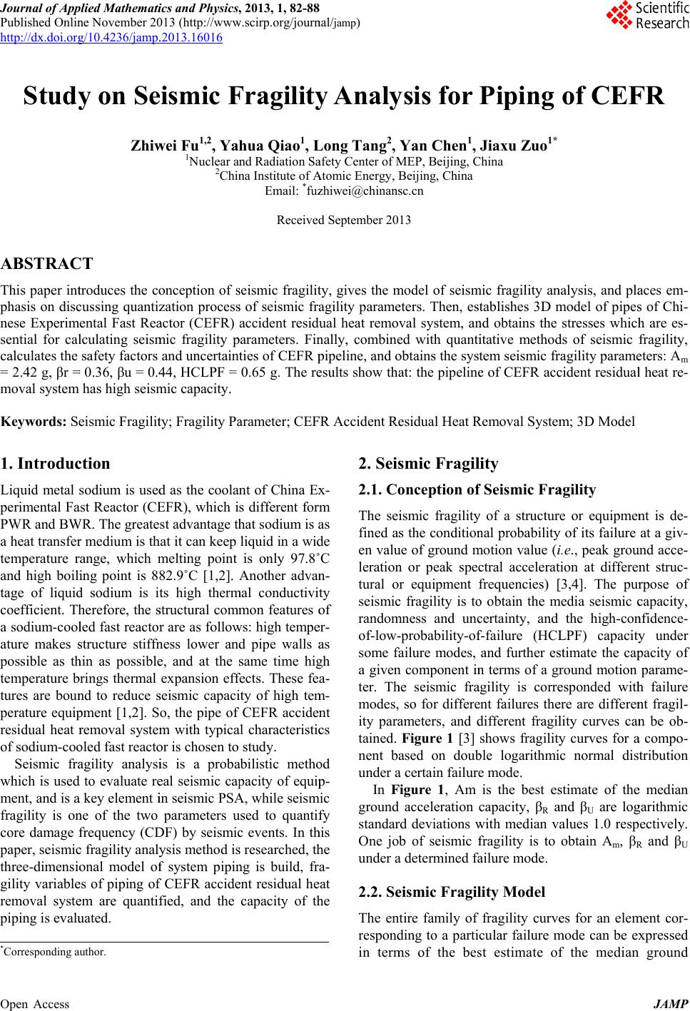 J ournal o f A pp Published Onli n http://dx.doi.or g Open Access Stud y ABSTRA C This paper in t phasis on dis c nese Experi m sential for ca l calculates the = 2.42 g, βr = moval system Keywords: S e 1. Introdu c Liquid metal p erimental F a PWR and B W a heat transfe r temperature r and high boil i tage of liqui d coefficient. T h a sodium-coo l ature makes s p ossible as t h temperature b tures are bou n p erature equi p residual heat r of sodium-co o Seismic fr a which is use d ment, and is a fragility is o n core damage f p aper, seismi c three-dimensi o gility variabl e removal syst e p iping is eval u * Corresponding a p lied Mathemat i n e November 2 0 g /10.4236/jamp . y on S e Zhi w C T t roduces the c o c ussing quanti z m ental Fast Re a l culating seis m safety factors = 0.36, βu = 0. 4 has high seis m e ismic Fragili t c tion sodium is use d a st Reactor (C E W R. The greate r medium is t h r ange, which m i ng point is 8 d sodium is i h erefore, the s l ed fast reacto r s tructure stiff n h in as possibl e b rings thermal n d to reduce s p ment [1,2]. S r emoval syste m o led fast react o a gility analys i d to evaluate r e a key element i n e of the two f requency (C D c fragility anal y o nal model o f e s of piping o f e m are q uanti f u ated. a utho r . i cs and Physics , 0 13 (http://ww w .2013.16016 e ismic F w ei Fu 1,2 , Ya 1 Nuclear a n 2 Chi n o nception of s z ation p roces s a cto r (CEFR) m ic fragility p and uncertain t 4 4, HCLPF = m ic capacity. t y; Fragility P a d as the coola n E FR), which i st advantage t h h at it can keep m elting point 82.9˚C [1,2]. ts high ther m s tructural com m r are as follo w n ess lower an d e , and at the s expansion ef f s eismic capac i o, the pipe o f m with typic a or is chosen to i s is a prob a e al seismic ca p i n seismic PS A parameters u D F) by seismi c y sis method i s f system pipi n f CEFR accid e f ied, and the , 2013, 1, 82-8 8 w .scirp.org/jour n F ragilit y h ua Qiao 1 , L nd Radiation S a n a Institute of A Email: * fu z Receive d s eismic fragili t s of seismic fr a acciden t resid u p arameters. Fi n t ies of CEFR p 0.65 g. The r e a rameter; CE F n t of China E x s different fo r m h at sodium is a liquid in a wi d is only 97.8 ˚ A nother adva n m al conductivi t m on features o w s: high temp e d pipe walls a s ame time hi g f ects. These fe i ty of high te m CEFR accide n a l characteristi c study. a bilistic meth o p acity of equi p A , while seis m u sed to quanti f c events. In t h s researched, t h n g is build, f r e nt residual he capacity of t h 8 n al / jamp ) y Anal y L ong Tang 2 , a fety Center of M A tomic Energy, B z hiwei@chinan s d September 20 t y, gives the m a gility p aram e u al heat remo v n ally, combin e p ipeline, and o e sults show th a F R Accident R e x - m a s d e ˚ C n - t y o f e r- a s g h a- m - n t c s o d p - m ic f y h is h e a- e at h e 2. Sei s 2.1. C o The se i fined a s en val u leratio n tural o seismi c rando m of-low - some fa a give n ter. T h modes, ity par a tained. nent b a under a In F ground standa r One jo b under a 2.2. S e The en respon d in ter m y sis for Yan Chen 1 , M EP, Beijing, C B eijing, China s c.cn 13 m odel of seis m e ters. Then, es v al system, a n ed with quant i o btains the sys a t: the p ipelin e e sidual Heat R s mic Fra g i l o nception o f i smic fragilit y s the conditio n u e of ground m n or peak spe c r equipment f c fragility is t o m ness and un c - probability-o f fa ilure modes, n component i n h e seismic fr a so for differ e a meters, and d Figure 1 [3] a sed on dou b a certain failur e F i g ure 1, Am acceleration r d deviations w b of seismic f a determined f a e ismic Fragi l tire family of d ing to a parti m s of the be s Piping Jiaxu Zuo 1* C hina m ic fragility a n tablishes 3D m n d obtains the i tative metho d te m seismic f r e of CEFR ac c R emoval Syste m l it y f Seismic Fr a y of a structu r n al probabilit y m otion value ( i c tral accelera t f requencies) [ o obtain the m c ertainty, and f -failure (HC L and further e s n terms of a g r a gility is corr e e nt failures th e d ifferent fragi l shows fragilit y b le logarithm i e mode. is the best e s c apacity, β R a w ith median v f ragility is to a ilure mode. l ity Model fragility curv e cular failure m s t estimate o f of CE F n alysis, and p l a m odel of p ipe s stresses whic h d s of seismic f r agility p aram e c iden t residua l m ; 3D Model a gility r e or equipme n y of its failure i .e., peak gro u t ion at differe n [ 3,4]. The pu r m edia seismic c the high-co n L PF) capacit y s timate the ca p r ound motion e sponded wit h e re are differe n l ity curves ca n y curves for a i c normal dis s timate of t h e a nd β U are lo g alues 1.0 resp obtain A m , β R e s for an ele m m ode can be e x f the median JAMP FR a ces em- s of Chi- h are es- f ragility, e ters: A m l heat re- n t is de- at a giv- u nd acce- n t struc- r pose of c apacity, n fidence- y under p acity of para m e- h failure n t fragil- n be ob- a compo- tribution e median g arithmic ectively. R and β U m ent cor- x pressed groun d  Open Access Fig u acceleration c Thus, the gro u [4]: in which R e values of 1. 0 randomness a median value . U e are logn o dard deviatio n the assumptio fragility curv e ditional prob a leration is giv f in which Q is dard Gaussia n brackets. 2.3. Fragilit y Quanti f Before you b save the con t and graphic f u re 1. Mean, m e c apacity, Am, u nd accelerati o m A A and U e are r 0 , representin g a bout the med i . In this mode l o rmally distri b n s, R and n and the equ a e s for structur e a bility of its fa i en by [5]: ln( ) ' m a A f called confid n cumulative y Analysis V f ication Met h egin to form a t ent as a sepa r f iles separate e dian, 5% non - and two ra n o n capacity, A m RU ee r andom variab g , respectivel y i an and the u n l , we assume t h b uted with l o U , respecti v a tion (1), we c e s or equipme n ilure at a give n 1 ) () U R Q ence and 1 distribution V ariables an d h od a t your paper, r ate text file. until after th e Z. W. - exceedance, a n n dom variabl e , is given by ( ( les with medi a y , the inhere n n certainty in t h h at both R ea n o garithmic sta n v ely. So due t c an obtain easi l n t, and the co n n value of acc ( 2 1 [] is the sta n of the term i d Their first write a n Keep your te x e text has be e FU ET AL. n d 95% non-e x e s. 1) 1) a n n t h e nd n - t o ly n - e- 2 ) n - i n n d x t e n format t of har d graph. the pa p In e s work i n the fac acceler specifi e level s p in whi c ground fy the strengt h And related as: For e ture re s p acity f Gen e x ceedance fragi l t ed and styled . d returns to o n Do not add a p er. Do s timating frag n terms of an tor of safety. ation capacit y e d for design; p ecified for de c h A is the ac t . This relatio n conservatis m h and the resp o so the media n to the media n A e quipment, th s ponse factor, f actor, as: F e rally, the ele m l ity curves for a . Do not use h n ly one retur n a ny kind of p a i lity paramet e intermediate r The factor o f y above a refe r e.g., the safe sign, A, is de fi SSE A FA t ual capacity o n ship is typica l m or factor o o nse, as: CR FFF n factor of safe n ground acce l mm SSE A FA e factor of s a equipment r e E RS RE C F FFF m ents which c a component. h ard tabs, and l n at the end o f a gination any w e rs, it is conv e r andom variab f safety, F, o n r ence level ea r shutdown ea r fi ned as follow o n acceleratio n l ly expanded t o f safety in b ty, Fm, can b e l eration capac a fety consists o e sponse factor C c an affect stru JAMP 83 l imit use f a pa r a- w here in e nient to le called n ground r thquake r thquake s [3,4]: (3) n motion t o iden t i- b oth the (4) e directly c ity, Am, (5) o f struc- and ca- (6) cture r e-  Z. W. FU ET AL. Open Access JAMP 84 sponse involve ground motion (such as earthquake re- sponse spectrum shape, horizontal direction peak re- sponse, and vertical component response), damping, modeling, mode combination, time history simulation, foundation-structure interaction, and earthquake combi- nation. The elements which can affect equipment re- sponse, similar to the above, include qualification me- thod, damping, modeling, mode combination, earthquake combination. Note that in order to avoid duplicating, earthquake combination only is considered in equipment response [6,7]. The capacity factor FC for the equipment is the ratio of the acceleration level at which the equipment ceases to perform its intended function to the seismic design level. And the factor FC can be calculated by the strength fac- tor FS and the inelastic energy absorption factor Fμ, as (7) [5]. CSμ FFF (7) The strength factor, FS, represents the ratio of ultimate strength (or strength at loss-of-function) to the stress calculated for acceleration at safety shutdown earthquake (ASSE). In calculating the value of FS, the non-seismic portion of the total load acting on the structure is sub- tracted from the strength as follows: N S TN SP FPP (8) where S is the strength of the structural element for the specific failure mode, N P is the normal operating load (i.e., dead load, operating temperature load, etc.) and T P is the total load on the structure (i.e., sum of the seismic load for SSE and the normal operating load). For higher earthquake levels, other transients may have a high probability of occurring simultaneously with the earth- quake. The definition of in such cases should be ex- tended to include the loads from these transients. Randomness and uncertainty are the two important parameters in seismic fragility analysis, so when deter- mining the safety factors the two parameters should be determined too [7]. 3. Stress Calculation of CEFR Accident Residual Heat Removal System Piping 3.1. Basic Condition of the Piping CEFR accident residual heat removal system has two loops, and one loop mainly includes an independent heat exchanger, an air heat exchanger and piping. The layout of one loop is as Figure 2 [2]. The material of the piping is 304H, and the size of the piping is as Figure 2. The piping material of argon sys- tem for accident residual heat removal system is 304 L, and the piping size is Φ48 × 4. The piping material of sodium analysis and monitoring system for accident Figure 2. Layout of one loop’s piping of CEFR accident residual heat removal system. residual heat removal system piping is 304 H, and the size of double piping are Φ108 × 4.5 and Φ48 × 4. 3.2. Modeling for the Piping The finite element method is used, and the AutoPIPE software is chosen as analysis tool. The 3D continuous pipeline is dispersed many space tube units, and the units are connected by nodes. The connection points of equip- ment and piping are taken as boundary conditions, and the displacement is given according to the thermal ex- pansion. The valves are simulated by valve units taking account into the impact of the quality of electric head. The treatment of double pipe is built two tubes, one of which is a relatively small amount of displacement, the pipeline where there is a shim in practice is connected with the guide frame. The model of one loop is shown in Figure 3. 3.3. Stress Calculation and the Selection of Fragile Parts To calculate the capacity factor of the piping, the stresses generated by both normal operating conditions and safety shutdown earthquake (SSE) load are needed, so the loads should be applied to the model. 3.3.1. Determina t ion and Loading of Loads Assumed that when the earthquake occurring, the reactor is in normal operation condition, and the system is in the normal standby condition, so the loads on the pipe can be determined when the earthquake occurring. 1) Loads under normal operation condition Loads under normal operation condition include pressure 0.402 MPa, weight, the constraint force and thermal load of 485˚C. Put the combination of these loads to the mod- el, then can get the stress N σ.  Z. W. FU ET AL. Open Access JAMP 85 Figure 3. Model of piping. 2) Loads under SSE condition According to above assumption, loads under SSE con- dition include the load caused by the SSE in addition to the loads under normal operation condition. The load caused by the SSE can be loaded by seismic response spectrum, which comes from reference [2]. The spec- trums used in the calculation are about four high levels 22.4 m, 26.6 m, 30.8 m and 35 m, and each level has three response spectrums, two horizontal and one vertical. The response spectrums about 5% damping are put in the AutoPIPE software, then the seismic response spectrum about SSE can be determined as Figure 4. 3.3.2. F r agile Points and Their Str e s s e s When determining the fragile points, two methods are used. One method is to choose the points where the stress SSE σ caused by the SSE load is the maximum, the other is to choose the points where the stress NSSE σ caused by both the loads in the normal operation condition and the SSE load is maximum. The points determined by the two methods are often not the same point, because the thermal expansion effects have been considered in the design stage. The SSE load and the combination of SSE load and the normal loads loaded on the model one after another, the points inside and outside the pipe where the stresses are maximum are choose respectively as Figure 5 and Figure 6. The fragile points and their stresses are shown in Table 1. 4. Fragility Analysis and Calculation of CEFR Piping 4.1. Calculation of Response Factor Building structural response factor is calculated by NU- REG0098 [8] factor median spectrum proportion and RG1.60 [9] spectrum proportion, and the piping response factor is calculated using the NUREG0098 median spec- trum proportion and design floor response spectrum. The calculated median factor and uncertainty are as follows: Building located on the fifth floor structural response median factor, randomness and uncertainty are SR F1.0 , RSR β0.31, USR β0.33. Building located on the eighth floor structural response median factor, randomness and uncertainty are SR F0.7, RSR USR β0.31,β0.33. When calculating the response factor of the pipe, the response factor is only considered in damping factor, and the randomness and uncertainty are only considered in other factors. The calculated damping factors and uncer- tainty are as follows: The pipe located on the fifth floor damping factor and uncertainty are D F1.8 , UD β0.22; The pipe located on the eighth floor damping factor and uncertainty are 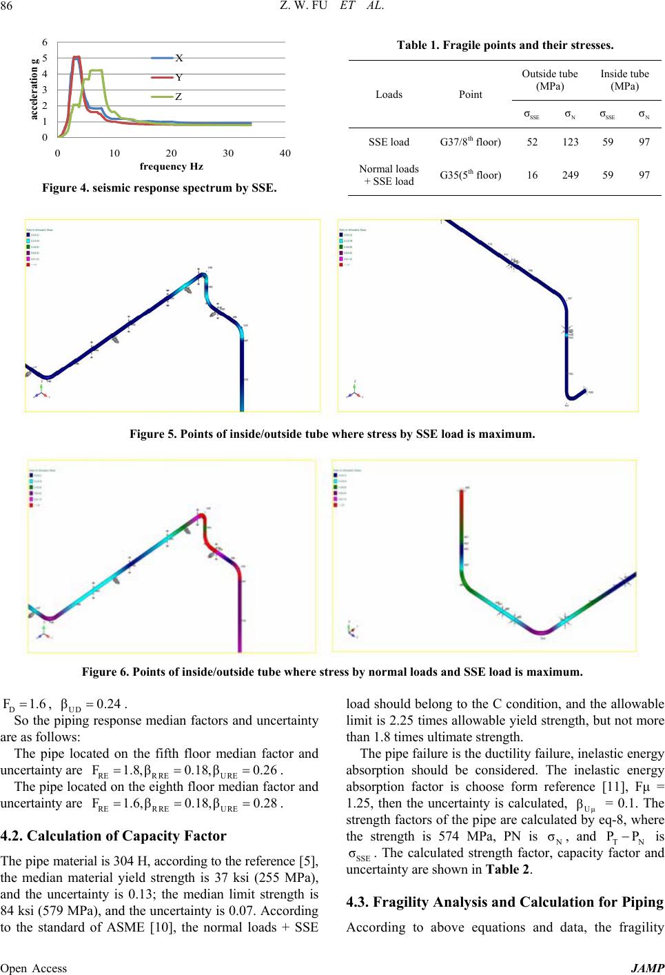 Z. W. FU ET AL. Open Access JAMP 86 Figure 4. seismic response spectrum by SSE. Table 1. Fragile points and their stresses. Loads Point Outside tube (MPa) Inside tube (MPa) SSE σ N σ SSE σN σ SSE load G37/8th floor)52 123 59 97 Normal loads + SSE load G35(5th floor)16 249 59 97 Figure 5. Points of inside/outside tube where stress by SSE load is maximum. Figure 6. Points of inside/outside tube where stress by normal loads and SSE load is maximum. D F1.6, UD β0.24. So the piping response median factors and uncertainty are as follows: The pipe located on the fifth floor median factor and uncertainty are RER REURE F1.8,β0.18,β0.26 . The pipe located on the eighth floor median factor and uncertainty are RER REU RE F1.6,β0.18,β0.28 . 4.2. Calculation of Capacity Factor The pipe material is 304 H, according to the reference [5], the median material yield strength is 37 ksi (255 MPa), and the uncertainty is 0.13; the median limit strength is 84 ksi (579 MPa), and the uncertainty is 0.07. According to the standard of ASME [10], the normal loads + SSE load should belong to the C condition, and the allowable limit is 2.25 times allowable yield strength, but not more than 1.8 times ultimate strength. The pipe failure is the ductility failure, inelastic energy absorption should be considered. The inelastic energy absorption factor is choose form reference [11], Fμ = 1.25, then the uncertainty is calculated, Uμ β = 0.1. The strength factors of the pipe are calculated by eq-8, where the strength is 574 MPa, PN is N σ, and TN PP is SSE σ. The calculated strength factor, capacity factor and uncertainty are shown in Table 2. 4.3. Fragility Analysis and Calculation for Piping According to above equations and data, the fragility 0 1 2 3 4 5 6 0 10203040 acceleration g frequency Hz X Y Z 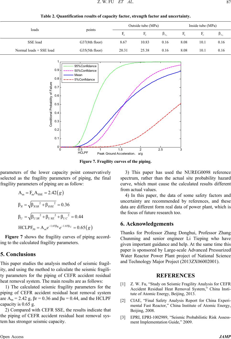 Z. W. FU ET AL. Open Access JAMP 87 Table 2. Quantification results of capacity factor, strength factor and uncertainty. loads points Outside tube (MPa) Inside tube (MPa) S F C F C U β S F C F C U β SSE load G37(8th floor) 8.67 10.83 0.16 8.08 10.1 0.16 Normal loads + SSE load G35(5th floor) 20.31 25.38 0.16 8.08 10.1 0.16 Figure 7. Fragility curves of the piping. parameters of the lower capacity point conservatively selected as the fragility parameters of piping, the final fragility parameters of piping are as follow: mmSSE A4A2F2. g 22 ββ β0.36 RRSRRRE 222 ββββ 0.44 UUSRUREUC U R1.65β 1.65β 50 m HCLPF 0.65Aee g Figure 7 shows the fragility curves of piping accord- ing to the calculated fragility parameters. 5. Conclusions This paper studies the analysis method of seismic fragil- ity, and using the method to calculate the seismic fragili- ty parameters for the piping of CEFR accident residual heat removal system. The main results are as follows: 1) The calculated seismic fragility parameters for the piping of CEFR accident residual heat removal system are Am = 2.42 g, βr = 0.36 and βu = 0.44, and the HCLPF capacity is 0.65 g. 2) Compared with CEFR SSE, the results indicate that the piping of CEFR accident residual heat removal sys- tem has stronger seismic capacity. 3) This paper has used the NUREG0098 reference spectrum, rather than the actual site probability hazard curve, which must cause the calculated results different from actual values. 4) In this paper, the data of some safety factors and uncertainty are recommended by references, and these data are different form real data of power plant, which is the focus of future research too. 6. Acknowledgements Thanks for Professor Zhang Donghui, Professor Zhang Chunming and senior engineer Li Tieping who have given important guidance and help. At the same time this paper is sponsored by Large-scale Advanced Pressurized Water Reactor Power Plant project of National Science and Technology Major Project (2013ZX06002001). REFERENCES [1] Z. W. Fu, “Study on Seismic Fragility Analysis for CEFR Accident Residual Heat Removal System,” China Insti- tute of Atomic Energy, Beijing, 2013. [2] CIAE, “Final Safety Analysis Report for China Experi- mental Fast Reactor,” China Institute of Atomic Energy, Beijing, 2008. [3] EPRI, EPRI-1002989, “Seismic Probabilistic Risk Assess- ment Implementation Guide,” 2009. 00.5 11.5 22.5 3 0 0.1 0.2 0.3 0.4 0.5 0.6 0.7 0.8 0.9 1 , P eak Ground Accel erationa/g * Conditional Probability of Failure HCLP F o 95%Confidance 50%Confidance Mean 5%Confidance  Z. W. FU ET AL. Open Access JAMP 88 [4] EPRI, EPRI 1019200, “Seismic Fragility Application Update Guide,” Palo Alto, 2009. [5] EPRI, EPRI-TR-103959, “Methodology for Developing Seismic Fragilities,” Palo Alto, 1994. [6] EPRI, EPRI-1002988, “Seismic Fragility Application Guide,” Electric Power Research Institute (EPRI), Palo Alto, 2002. [7] Z. W. Fu, D. H. Zhang, C. M. Zhang, et al., “Study on Equipment Seismic Fragility Analysis Method,” Nuclear Science and Engineering, Vol. 33, No. 2, 2013, pp. 213- 218. [8] N. M. Newmark and W. J. Hall, “Development of Criteria for Seismic Review of Selected Nuclear Power Plants,” NUREG/CR-0098, 1978. [9] USNRC, “Regulatory Guide 1.60 Design Response Spec- tra for Seismic Design of Nuclear Power Plants,” 1973 [10] ASME, “ASME II-D Performance,” 2004. [11] DOE, “Natural Phenomena Hazard Design and Evalua- tion Criteria for Department of Energy Facilities,” DOE- STD-1020-2002: DOE STANDARD, 2002. |