H. LI ET AL.
Open Access JAMP
driving force of crack growth [9] is:
(1)
Type:
µ
is the contact surface friction coefficient, P0 is
the contact pressure (Pa), S is the fretting slip amplitude
(M), K is formula constant having a length dimension
(m). Specimens of stress which fatigue crack initiation
required is
σ
f, load stress which lead to specimen’s fati-
gue crack is
σ
ff.
σ
ff is the component's fatigue strength
fretting and
σ
f is the component’s fatigue strength no
fretting. Fatigue strength in a micro component is smaller
than which without fretting, which can be seen from this
formula, and the difference between the two depends on
P0,
µ
and S, that is to say the fretting fatigue strength is
related to friction coefficient, contact pressure and slip
amplitude and so on, yet the slip amplitude is directly
related to fatigue loading. So, based on the above men-
tioned theory, the fretting fatigue contact geometry of a
riveted two aluminum specimen was studied using the
finite element method. The contact stress fields of the
inner and outer contact edges on the two specimen’s up
and down surface under different contact friction coeffi-
cient and the fatigue loads were analyzed, the influences
of the contact friction coefficient and remote stress on
crack initiation and propagation mechanism were dis-
cussed.
3. Modeling
3.1. Computational Model
The 3D finite element model of the rived aluminum spe-
cimen and its meshing result are showed in Figure 1. In
order to reduce the computational cost, only half of the
FEM model is constructed according to the symmetries
of the specimen. The model is composed of 8 parts, in-
cluding two aluminum plates, one screw bolt, one protec-
tive sleeve, two screw caps and two gaskets. In order to
further reduce the model size and computational cost, the
reducing of the meshing numbers and contact areas is →
are often adopted in the FEM simulation. Thus, we treat
the screw bolt, the protective sleeve, the screw caps and
the gaskets as an integrated section to neglect the con-
tacts between those parts. Three contacts regions are in-
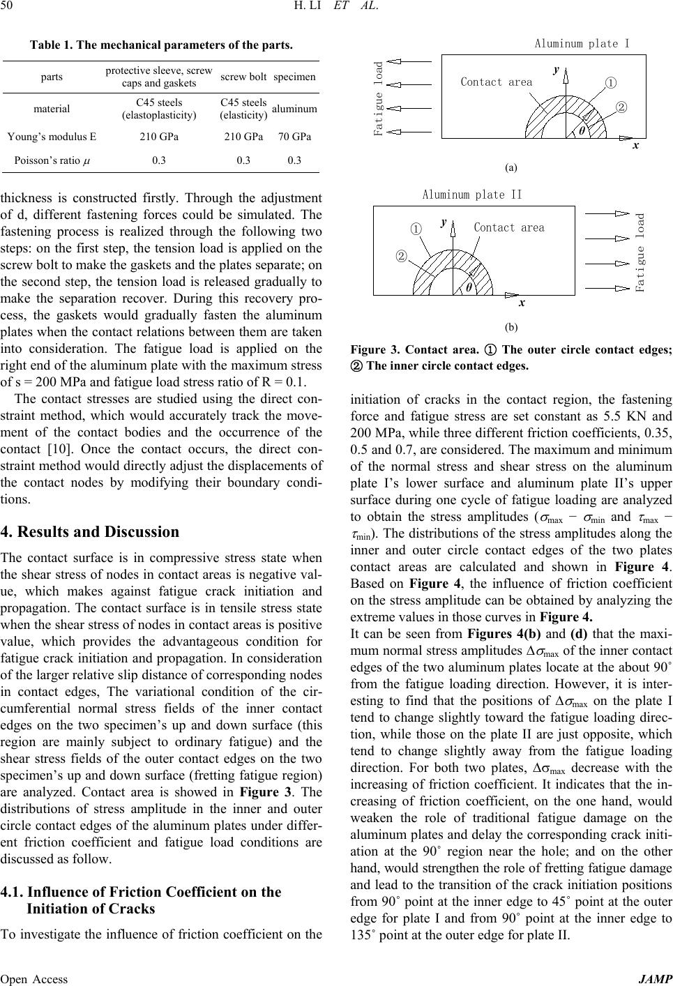
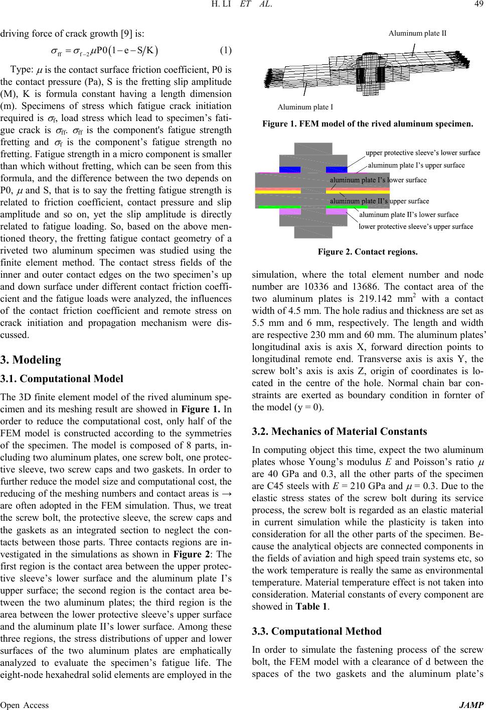
vestigated in the simulations as shown in Figure 2: The
first region is the contact area between the upper protec-
tive sleeve’s lower surface and the aluminum plate I’s
upper surface; the second region is the contact area be-
tween the two aluminum plates; the third region is the
area between the lower protective sleeve’s upper surface
and the aluminum plate II’s lower surface. Among these
three regions, the stress distributions of upper and lower
surfaces of the two aluminum plates are emphatically
analyzed to evaluate the specimen’s fatigue life. The
eight-node hexahedral solid elements are employed in the
Figure 1. FEM model of the rived aluminum specimen.
Figure 2. Contact regions.
simulation, where the total element number and node
number are 10336 and 13686. The contact area of the
two aluminum plates is 219.142 mm2 with a contact
width of 4.5 mm. The hole radius and thickness are set as
5.5 mm and 6 mm, respectively. The length and width
are respective 230 mm and 60 mm. The aluminum plates’
longitudinal axis is axis X, forward direction points to
longitudinal remote end. Transverse axis is axis Y, the
screw bolt’s axis is axis Z, origin of coordinates is lo-
cated in the centre of the hole. Normal chain bar con-
straints are exerted as boundary condition in fornter of
the model (y = 0).
3.2. Mechanics of Materia l Constants
In computing object this time, expect the two aluminum
plates whose Young’s modulus E and Poisson’s ratio
µ
are 40 GPa and 0.3, all the other parts of the specimen
are C45 steels with E = 210 GPa and
µ
= 0.3. Due to the
elastic stress states of the screw bolt during its service
process, the screw bolt is regarded as an elastic material
in current simulation while the plasticity is taken into
consideration for all the other parts of the specimen. Be-
cause the analytical objects are connected components in
the fields of aviation and high speed train systems etc, so
the work temperature is really the same as environmental
temperature. Material temperatu re effect is not taken into
consideration. Material constants of every component are
showed in Table 1.
3.3. Computational Method
In order to simulate the fastening process of the screw
bolt, the FEM model with a clearance of d between the
spaces of the two gaskets and the aluminum plate’s